


TF corsair, prototype scheme
 01-21-2003 | 07:23 PM
#1
Thread Starter
Senior Member
Joined: Sep 2002
Posts: 373
Likes: 0
Received 0 Likes
on
0 Posts
From: BROOKLYN,
NY
I like seeing other threads on construction, and i'm bashing a topflite 60" corsair into the prototype, i figured it would be a good thread to show my modifications, especialy for anone else wanting to do it. I'll skim over what i do that follows the manual to save words, and concentrate on my modifications.
any hints, suggestions, or questions are more than welcome.
Pictures will follow soon (have to learn how to use my new-fangled digital camera i just got)
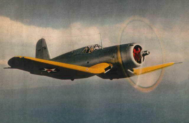
I started by getting Detail and Scale volume 55, corsair and showing my wife the different color schemes and asking her opinion, of course she liked the silver and yellow of the prototyp (US pre-involvement neutrality colors). so to faithfuly reproduce the prototype, the cockpit had to come forward, and the firewall/cowl aft, and a new canopy will be fabricated when I get that far. I'm using Century Jet retrats, mainly based on price. they appear quite sturdy, if not the highest points for spit and polish.
any hints, suggestions, or questions are more than welcome.
Pictures will follow soon (have to learn how to use my new-fangled digital camera i just got)
I started by getting Detail and Scale volume 55, corsair and showing my wife the different color schemes and asking her opinion, of course she liked the silver and yellow of the prototyp (US pre-involvement neutrality colors). so to faithfuly reproduce the prototype, the cockpit had to come forward, and the firewall/cowl aft, and a new canopy will be fabricated when I get that far. I'm using Century Jet retrats, mainly based on price. they appear quite sturdy, if not the highest points for spit and polish.
 01-21-2003 | 07:48 PM
#2
Thread Starter
Senior Member
Joined: Sep 2002
Posts: 373
Likes: 0
Received 0 Likes
on
0 Posts
From: BROOKLYN,
NY
I built the tail feathes as per plans, and adde lightening holes to help compensate for the engine moving aft almost an inch. I also added 2 t-nuts along the centreline, to use small wing bolts to attach, making transport that much easier, and incidence alteration if necicary.
01-21-2003 | 08:07 PM
#3
Thread Starter
Senior Member
Joined: Sep 2002
Posts: 373
Likes: 0
Received 0 Likes
on
0 Posts
From: BROOKLYN,
NY
The wing was built mostly to plan, but as you can see from the picture, I changed the centre sheetind arangement for a more scale apearance. I didn't add the R-4b and 5b sub-ribs in step 10, and omitted the centre section flat sheeting which was totaly un-necicary and creates a flat spot between the wing and the belly pan. instead I brought the wing sheeting past r-2 and in-to r-1 with a smooth transition, the belly pan will meet flush with the wing sheeting between r-1 and r-2. the main spar was notched to not stick out of the sheeting where the wing and belly pan meet.
I also threw away the heavy, warped solid aileron/flap stock and built up the flaps. the middle flap was narowed about 1/2 on each side to match the scale 3-view drawings, and the use of the robart hinge points was changed. I mounted them verticaly into the flap, gluing strait onto the flap LE, and the other half lays flat on the wing sheeting, to be fibreglassed down. this puts the hinge behind the flap/wing split line, as on the original, and is much easier to align than trying to drill 12 holes at 30 degrees, just the right height.......(i tried)
I also threw away the heavy, warped solid aileron/flap stock and built up the flaps. the middle flap was narowed about 1/2 on each side to match the scale 3-view drawings, and the use of the robart hinge points was changed. I mounted them verticaly into the flap, gluing strait onto the flap LE, and the other half lays flat on the wing sheeting, to be fibreglassed down. this puts the hinge behind the flap/wing split line, as on the original, and is much easier to align than trying to drill 12 holes at 30 degrees, just the right height.......(i tried)
01-21-2003 | 08:12 PM
#4
Thread Starter
Senior Member
Joined: Sep 2002
Posts: 373
Likes: 0
Received 0 Likes
on
0 Posts
From: BROOKLYN,
NY
I added hatches for flap servo access, because of murphys law. if i didn't put them in now i'd need them there later. the re-location of the flap hinges allowed the horn to be installed "upside down" into the flap, so the pushrod is hidden within the wing, less drag, and looks a bit better. I'm also using mini servos for the ailerons instead of a single unit in the centre, which would work fine on a flat wing, but on the corsair there's just too sharp an angle of attachment from the snake to the servo, as shown on the plans, i suppose if the servo is upside down it would be smoother, but 2 servos is just as easy of a modification.
 01-21-2003 | 10:03 PM
#7

My Feedback: (81)
Hey shupak...I like the prototype and like the looks of it. To add to your scale realism, you will need to remove the round tailcone and put a blunt chunk of balsa back there. The prototype had a drag chute that deployed out the rear end where the tailcone sits. Jsut FYI 
01-21-2003 | 10:21 PM
#8
Thread Starter
Senior Member
Joined: Sep 2002
Posts: 373
Likes: 0
Received 0 Likes
on
0 Posts
From: BROOKLYN,
NY
thanks f4u, but it wasn't a drag chute, it was the tailhook, it came out of the tail cone like on wildcats, it was changed to being integral with the tailwheel on the production run. i'm still trying to decide the best way to do it, so I decided to practice my shaping skills on the tailcone. every time i notice a new bit of scale detail, i notice somthing else I did wrong! I just noticed I messed up the turtledeck shape when i moved the cockpit forward, how to fix that, hmm......
psycho, here's a photo of the 3views i have, i'll scan it and e-mail if you'd like
psycho, here's a photo of the 3views i have, i'll scan it and e-mail if you'd like
01-21-2003 | 10:26 PM
#9
Thread Starter
Senior Member
Joined: Sep 2002
Posts: 373
Likes: 0
Received 0 Likes
on
0 Posts
From: BROOKLYN,
NY
you can see the mistake I made with the turtledeck in this shot, I didn't shorten F-7 to make a smooth curve from canopy to tail, i just added on a chunk of balsa, and raised f-5 and moved it 3/4" aft. the question is, can i sand it smooth, or will I run out of block, and have to cut and re-build. any suggestions?
01-23-2003 | 05:47 PM
#10
Thread Starter
Senior Member
Joined: Sep 2002
Posts: 373
Likes: 0
Received 0 Likes
on
0 Posts
From: BROOKLYN,
NY
that took care of it, i decided that if I started sanding and ran out of block, i'd have to cut and replace anyway, so I broke out the razor plane, then started sanding, slowly. thank goodness for 3M "sandblaster" sandpaper, the stuff works like a dream, chews through balsa faster than my black lab, and leaves a perfect finish. I used a square of 100 grit glued to soft foam, and started with "short strokes" right on the high point, untill it was nice and smooth, and about 1/2" of dust on the work table.
01-23-2003 | 11:02 PM
#15
Thread Starter
Senior Member
Joined: Sep 2002
Posts: 373
Likes: 0
Received 0 Likes
on
0 Posts
From: BROOKLYN,
NY
here's the retract gear setup, all in the wing for ease, so I only have to plug in the servo wire, instead of 2 quick-connects, which have the chance of leaking. you can also see on the aileron lead the number marker, salvaged off of an old electrical panel i de-commisioned. #1 for reciever channel #1, the retract lead is marked #6, but it's blue and harder to see. the little plastic numbers can probably be found at an electrical equipment wholesaler/supplier. the servo and valve are mounted to the supplied lite-ply plate, and a lite ply rail with balsa support is ca'd to the rib. the air cylinder is held down by the plate and firm by soft foam.
the directions for the air-valve recommended a solid piece of push-rod, 2 chunks of inner snake, some fuel tubing and 3 wheel colars. i just used a piece of pushrod, 2 chunks of goldenrod inner, and a length of 2-56 all thread. the pushrod goes to the first piece of goldenrod inner, which is adjusted for length with the servo "down" to push the cylinder just to the edge of the valve body, the all thread is threaded into the first piece of inner, and cut off with 1/2" to spare, the servo is put "up", then the second piece of inner is threaded on to push the valve cylinder to the other side of the valve body. check several times for correct alignment and voila! same function, 1/3 the parts count (and I would guess half of the setup time)
the directions for the air-valve recommended a solid piece of push-rod, 2 chunks of inner snake, some fuel tubing and 3 wheel colars. i just used a piece of pushrod, 2 chunks of goldenrod inner, and a length of 2-56 all thread. the pushrod goes to the first piece of goldenrod inner, which is adjusted for length with the servo "down" to push the cylinder just to the edge of the valve body, the all thread is threaded into the first piece of inner, and cut off with 1/2" to spare, the servo is put "up", then the second piece of inner is threaded on to push the valve cylinder to the other side of the valve body. check several times for correct alignment and voila! same function, 1/3 the parts count (and I would guess half of the setup time)
01-23-2003 | 11:07 PM
#16
Thread Starter
Senior Member
Joined: Sep 2002
Posts: 373
Likes: 0
Received 0 Likes
on
0 Posts
From: BROOKLYN,
NY
here's a small modification i've made to my CJ retrats. the spring to twist the retracts back into the well isn't strong enough, including increasing tension) and the wheen the wheels snap back (havn't had the cash to buy the adjsutable valve yet) they were getting stuck 1/2 rotated into the well.
it's just a piece of 4/40 scrap bent into an L with a loop for the mounting screw. now the rotation pin gets pushed into the retract position positively.
(sorry it's blurry, too much zoom)
it's just a piece of 4/40 scrap bent into an L with a loop for the mounting screw. now the rotation pin gets pushed into the retract position positively.
(sorry it's blurry, too much zoom)
01-26-2003 | 09:44 AM
#17
Thread Starter
Senior Member
Joined: Sep 2002
Posts: 373
Likes: 0
Received 0 Likes
on
0 Posts
From: BROOKLYN,
NY
I've cleaned up the retract gear installation, secured the hoses and aileron servo leads. I already had the airlines set up with a T fitting to send one line up into the fuz, so I didn't have enogh line to plug both into the valve, so I ran one line from the valve to the T, and plugged the other valve outlet with a short chunk of line stuffed with a piece of pushrod scrap. the fill line is capped the same way with a qucik connect, the other end attached to my air pump. bend the line over twice, disconnect the pump and put on the cap, saves the weight of the heavy fill valve CJ supplies. I once heard on here somewhere, "mind the grams, and the ounces take care of themselves"
I also re-made my flap servo hatches, the odd sizes started to bug me really bad.
this shot also shows a little trick I can't remember where I learned. drill a hole in the top of your workbench the size of your wing dowel hole, set the wing dowel into it and you have a third hand to hold your wing, great for seting up retracts and wing controlls.
I've heard of running dual recievers to split the plane left and right for reliability, what about putting a reciever in the wing, then no fiddling with servo extensions, jsut bolt the wing on, 2 switches and go. this would add some reliability too, as the plane might be flyable with just aileron and flaps (some pitch controll) and is almost definaltely flyable with just rudder throttle and elevator. I'm not much of a pilot yet, what do you guys think about this setup?
01-26-2003 | 01:16 PM
#18


My Feedback: (85)
Shupack,
Your instillation looks real clean. But you have to spring for the adjustable valve About "Extras" that is the age old question : Is it a necessity or niceity? A glow driver is probably a necessity in this plane and mine will have one. Redundant Rx and Battery I would put in the niceity box. If your running a larger capacity battery and a new Rx I wouldn't add the weight in this size plane. (IMHO) Your going to glass it and like you said "Mind the grams..." Keep posting. Both you ,Juice and others posting have set a high bar for my Corsair. Pete
Your instillation looks real clean. But you have to spring for the adjustable valve
About "Extras" that is the age old question : Is it a necessity or niceity? A glow driver is probably a necessity in this plane and mine will have one. Redundant Rx and Battery I would put in the niceity box. If your running a larger capacity battery and a new Rx I wouldn't add the weight in this size plane. (IMHO) Your going to glass it and like you said "Mind the grams..." Keep posting. Both you ,Juice and others posting have set a high bar for my Corsair. Pete
01-26-2003 | 04:34 PM
#19
Senior Member
Joined: Nov 2002
Posts: 250
Likes: 0
Received 0 Likes
on
0 Posts
From: Woodward, IA
Shupack, usually a 2nd receiver will control the left aileron and right elevator, while the first controls the opposite.
This allows you partial control of the airplane.
I'm not sure that a warbird could be controlled with less than all 4 main channels, as I've read that they require coordinated turns to stay stable.
Could someone more experienced than I confirm this?
This allows you partial control of the airplane.
I'm not sure that a warbird could be controlled with less than all 4 main channels, as I've read that they require coordinated turns to stay stable.
Could someone more experienced than I confirm this?
01-26-2003 | 09:45 PM
#20
Thread Starter
Senior Member
Joined: Sep 2002
Posts: 373
Likes: 0
Received 0 Likes
on
0 Posts
From: BROOKLYN,
NY
Thanks for the encouragement rocketman, this is only my second plane. I will spring for the adjustable valve, but after i've sprung for an RCV 90, a dummy radial, glass cloth and epoxy, and 4 more servo's. and a glow driver is a definate for me too.
here's a few shots put together, although i'm still waiting for my tailwheel to arive to finish the botom of the fuz.
here's a few shots put together, although i'm still waiting for my tailwheel to arive to finish the botom of the fuz.
01-26-2003 | 09:49 PM
#21
Thread Starter
Senior Member
Joined: Sep 2002
Posts: 373
Likes: 0
Received 0 Likes
on
0 Posts
From: BROOKLYN,
NY
here you can see how i tapered the fuz to vent the cowl like the full size, and above you can see the secton of the wing i left open untill i fit and adjust the flap servos and hidden linkages
imagine seeing that coming at you with 2 .50's and 2 .30's blazing! (well, imagine it finished)
imagine seeing that coming at you with 2 .50's and 2 .30's blazing! (well, imagine it finished)
01-26-2003 | 11:19 PM
#22
I can Imagine that LOL
I like the Idea.
I'm planning on shortening the nose on mine to make it look more accurate. It seems to have a bit too long a nose. also relieving the area behind the cowl for airflow is a fantastic Idea. Good luck Shupack, I can't wait to see the finished product.
I like the Idea.
I'm planning on shortening the nose on mine to make it look more accurate. It seems to have a bit too long a nose. also relieving the area behind the cowl for airflow is a fantastic Idea. Good luck Shupack, I can't wait to see the finished product.
01-27-2003 | 02:50 PM
#23
Shupack,
You're doing great work. Keep the updates and pictures coming.
I am also using the RCV 90 and I was worried about the airflow. I rounded the circumference of the firewall and cut and opened up the cowl base to make cowl flaps. As you can see form the pictures, I have no more worries about outlet area. I calculate over 7 square inches of outlet area.
Juice
01-30-2003 | 03:31 PM
#24
Thread Starter
Senior Member
Joined: Sep 2002
Posts: 373
Likes: 0
Received 0 Likes
on
0 Posts
From: BROOKLYN,
NY
nothing new to photograph, i'm just sanding and filling cracks and dents getting ready to glass. I can't find polycrylic anywhere here (UK) so i'm going to use Z-poxy, but i have a few questions. should i remove the hatches and glass them separately? or can I just cut them out when dry? also, would 2 layers be benificial in the wheel wells to strengthen the wing, or don't bother?
juice, how did you cut and bend the cowl?
juice, how did you cut and bend the cowl?
01-31-2003 | 04:24 AM
#25
Junior Member
Joined: Jan 2003
Posts: 7
Likes: 0
Received 0 Likes
on
0 Posts
From: michigan
Hi,
Great job on those planes!
I am also building the TF Corsair. And I was wondering if you had any detailed pictures of how you mounted the aileron servos and which kind did you use? And what type of glass cloth are you going to use and the weight?
Thanks for all the great ideas!!!!
Great job on those planes!
I am also building the TF Corsair. And I was wondering if you had any detailed pictures of how you mounted the aileron servos and which kind did you use? And what type of glass cloth are you going to use and the weight?
Thanks for all the great ideas!!!!

