Go Back  RCU Forums > RC Airplanes > Kit Building
Reload this Page >

Byron 51 Build Thread

Community
Search
Notices
Kit Building If you're building a kit and have questions or want to discuss kit building post it here.

Byron 51 Build Thread

Thread Tools
 
Search this Thread
 
Old 09-01-2009, 04:19 PM
  #26  
Condor060
Thread Starter
My Feedback: (2)
 
Condor060's Avatar
 
Join Date: Jun 2009
Location: Monroe, NC
Posts: 494
Likes: 0
Received 0 Likes on 0 Posts
Default RE: Byron 51 Build Thread

I agree Bob. Like you, my interest is in keeping this scale. I am going to wind up with a heavier model than originally designed so I want SOME extra power. The goal is to keep that 3000-3200 rpm. I would even limit my throttle servo throw if the newer engine over spins the system.
I think I have the Q32 but the Q400 is the Q42 replacement. I saw the exhaust change but the 400B eliminates the mag and comes in at 3.73 lbs vs the Q400M at 4.53 lbs. I know it doesn’t include the battery weight.
I like what you said about the counterweights. I do plan to use individual servos for the Ailerons. OK, now I just had a thought. I can eliminate the two 24 inch aluminum aileron push rods, bearings, and 2 counterweights by adding the second servo for the ailerons. That’s a good weight exchange for one servo.
Do you know I didn’t even think about that until now. Wow, I should be singing right now, If I Only Had A Brain.

I am slow but I will eventually get it, just hang in there with me Bob.
Attached Thumbnails Click image for larger version

Name:	Xv64226.jpg
Views:	26
Size:	27.3 KB
ID:	1267144  
Old 09-01-2009, 04:43 PM
  #27  
masteromodels
My Feedback: (11)
 
Join Date: Apr 2002
Location: north port, FL
Posts: 731
Likes: 0
Received 0 Likes on 0 Posts
Default RE: Byron 51 Build Thread

One of the reasons about using the Qudra 40 with the magnito rater then the electronic ignition that when you try to idle the eng. the magnito helps counter the fly wheel effect. There was some on one of the byron threads that stated he was having a problem with the eng. idle and he thought the extra weight of the mag would help to keep it running. he had used an eng. with the electronic ignition.

thanks bob
Old 09-01-2009, 08:15 PM
  #28  
Tony Hallo
 
Join Date: Jan 2003
Location: Springdale, PA
Posts: 1,833
Received 50 Likes on 48 Posts
Default RE: Byron 51 Build Thread

The 40 I worked on had two rings and the piston measured sightly less than 1.500", about 1.490" if memory serves me correct. There were more than 35's made with two rings, you relly do need to measure your bore to be sure. Will try the g38 mag trick to be sure, thanks.
Old 09-07-2009, 08:48 AM
  #29  
Condor060
Thread Starter
My Feedback: (2)
 
Condor060's Avatar
 
Join Date: Jun 2009
Location: Monroe, NC
Posts: 494
Likes: 0
Received 0 Likes on 0 Posts
Default RE: Byron 51 Build Thread

I have been in a small holding pattern on my build because I was missing some plastic parts. The wind hold down saddles. I needed two front and two rear but only have one of each. I have been looking all over the net but this isn’t producing any results so I decided to make my own.


I located an amazing product called Insta-Mold at a craft shop (Michaels Crafts) and have learned how to reproduce any part I need. I can make parts out of epoxy, plastic, J&B Weld, or whatever I want as long as the curing process temperature doesn’t exceed 300 degrees.


Picture 1
I used a plastic paint brush/paint holder (container) to make my first mold. You can find these at any hardware store for pennies.


Picture 2
Plastic part I want to replicate


Picture 3
I mixed the Insta-mold with water (50/50) and poured the first half of my mold into the container. While the mold material is still liquid I inserted the plastic part I want to replicate. It is also important to insert at least two additional holes into the mold as alignment guides.
Once the mold is poured it only takes about 10 minutes to cure. Now you can mix up another batch and pour on top to create the top section of the mold. It is important to note that Insta-mold doesn’t stick to anything including itself.


Picture 4
New mold removed from container. I took a long thin flathead screw driver and ran it around the edges of the mold while in poped out with no problems.


Picture 5
Mold separated and ready to pour with the plastic piece I want to replicate removed. I mixed up some 5 minute epoxy and filled the center hole of the bottom mold. I placed the top of the mold back in position and the excess epoxy leaked down the sides of the mold.


Picture 6
This is the new wing saddle created beside the original


Picture 7
Insta-Mold Packaging.


You can add any dye or food coloring to your epoxy to make the part in any color you want. You can also purchase liquid plastic resin and catalyst if you want to make plastic parts. I even made one out of JB Weld.

Attached Thumbnails Click image for larger version

Name:	Yw66367.jpg
Views:	23
Size:	66.3 KB
ID:	1270345   Click image for larger version

Name:	Cy77525.jpg
Views:	22
Size:	51.0 KB
ID:	1270346   Click image for larger version

Name:	Sx61616.jpg
Views:	26
Size:	55.6 KB
ID:	1270347   Click image for larger version

Name:	Ke91051.jpg
Views:	20
Size:	72.4 KB
ID:	1270348   Click image for larger version

Name:	Yj64247.jpg
Views:	22
Size:	62.3 KB
ID:	1270349   Click image for larger version

Name:	Hy34563.jpg
Views:	26
Size:	69.8 KB
ID:	1270350   Click image for larger version

Name:	Wy50476.jpg
Views:	27
Size:	149.0 KB
ID:	1270351  
Old 09-07-2009, 12:58 PM
  #30  
mtnflyer14
 
mtnflyer14's Avatar
 
Join Date: Jan 2006
Location: Colorado Springs, CO
Posts: 530
Likes: 0
Received 0 Likes on 0 Posts
Default RE: Byron 51 Build Thread

I'm really glad you figured out a way to duplicate the wing pockets. I had all four in my kit but they are glassed in, so no way to help you. So you made your pocket out of 5 nimute epoxy - is it hard and brittle? Does Michaels sell the plastic resin also? Did you consider that for the pocket material? Sorry for so many questions, but this technique could be applied in so many ways in modeling. Thanks for sharing the find!
Regards,
Mark
Old 09-07-2009, 04:08 PM
  #31  
Condor060
Thread Starter
My Feedback: (2)
 
Condor060's Avatar
 
Join Date: Jun 2009
Location: Monroe, NC
Posts: 494
Likes: 0
Received 0 Likes on 0 Posts
Default RE: Byron 51 Build Thread

Yeah, I made one out of epoxy and one out of plastic resin. I think the plastic resin one is the way to go.
Old 09-09-2009, 11:45 PM
  #32  
Condor060
Thread Starter
My Feedback: (2)
 
Condor060's Avatar
 
Join Date: Jun 2009
Location: Monroe, NC
Posts: 494
Likes: 0
Received 0 Likes on 0 Posts
Default RE: Byron 51 Build Thread

It’s been a few days since I posted any progress so here’s the news.
I received an E-mail from Forest and his Byron 51 with video from his flight at Warbirds over Atlanta. You have to check this out, he did a great job. I just hate him lol http://www.youtube.com/watch?v=59WqvYXwnHY
I needed to smooth out the transition of the triangle stock glued to the ailerons and flaps. I used a light commercial spackle (photo #1) and took pictures of the before and after of one of the flaps after it was sanded. (Photo #2 and #3). It worked perfectly.
I have also decided to eliminate the two 24 inch aluminum push rods that extend from the center point of the wing to the ailerons (single servo) and replace that system with two servos. (Photo #4)
Update on the mold process. The kit was short two wing hold down saddles (One front and one rear) so I had to make them. They came out great, (Picture #5)
This picture is the Plastic resin I used to replicate the wing hold down saddles (Picture #6)
The rest is a picture of the Byron 51 construction hanger. I took over the garage and booted the cars to the driveway. This in turn is forcing me to complete the project before my family boots me out of the house.
Attached Thumbnails Click image for larger version

Name:	Zw69427.jpg
Views:	27
Size:	58.4 KB
ID:	1272079   Click image for larger version

Name:	Ez82143.jpg
Views:	23
Size:	44.8 KB
ID:	1272080   Click image for larger version

Name:	Lq36188.jpg
Views:	22
Size:	44.6 KB
ID:	1272081   Click image for larger version

Name:	Ga76384.jpg
Views:	29
Size:	42.1 KB
ID:	1272082   Click image for larger version

Name:	Sd45582.jpg
Views:	24
Size:	42.0 KB
ID:	1272083   Click image for larger version

Name:	Oe56634.jpg
Views:	24
Size:	62.8 KB
ID:	1272084   Click image for larger version

Name:	Ac65164.jpg
Views:	26
Size:	79.1 KB
ID:	1272085   Click image for larger version

Name:	Tr61507.jpg
Views:	26
Size:	76.2 KB
ID:	1272086  

Click image for larger version

Name:	Sq46827.jpg
Views:	20
Size:	61.9 KB
ID:	1272087  
Old 09-10-2009, 08:13 AM
  #33  
mtnflyer14
 
mtnflyer14's Avatar
 
Join Date: Jan 2006
Location: Colorado Springs, CO
Posts: 530
Likes: 0
Received 0 Likes on 0 Posts
Default RE: Byron 51 Build Thread

I have the single piece wing and aluminum tubes to ailerons also with single servo. How are you mounting the servo in the foam wing? Are you building a lite ply box inside the foam to which the servo will attach? I've already glassed my wing but could probably go back in and do the servo mod. Am also wondering if I can get the aileron extension to the wing center - could be a problem.
Thanks,
Mark
Old 09-10-2009, 08:56 AM
  #34  
Condor060
Thread Starter
My Feedback: (2)
 
Condor060's Avatar
 
Join Date: Jun 2009
Location: Monroe, NC
Posts: 494
Likes: 0
Received 0 Likes on 0 Posts
Default RE: Byron 51 Build Thread


Hey Mntflyer, I would be very interested in knowing what products you used in the fiberglass process of your wing along with any problems or success you had in the process. I am getting close to that process myself and I can't seem to find any threads thatparallelmy application. Would you mind giving me your thoughts on your experience in this? That would really be helpful. Although I have watched people glass wings I have only done it once and that was in 1979. I am a little outdated and confused as to what products to use for this.

I made the hole size 1/2 inch wider and longer than the servo. I am building a hardwood servo tray with a 1 inch glueable surface on all four sides and additional hardwood blocks to seat the servo. You can purchase servo extensions up to 48 inches (http://www.aero-works.net/store/detail.aspx?ID=166) along with servo connection clips to assure the extension can't come apart. The picture I made is not accurate. I plan to install the servo on its side with a metal extended servo arm. I will have a hatch cover to enable access to the servo with a small slot in the middle for the servo arm to extend to the outside surface of the wing.

Attached Thumbnails Click image for larger version

Name:	Tq48562.jpg
Views:	24
Size:	57.9 KB
ID:	1272195   Click image for larger version

Name:	Wu62217.jpg
Views:	27
Size:	43.8 KB
ID:	1272196  
Old 09-10-2009, 11:24 AM
  #35  
mtnflyer14
 
mtnflyer14's Avatar
 
Join Date: Jan 2006
Location: Colorado Springs, CO
Posts: 530
Likes: 0
Received 0 Likes on 0 Posts
Default RE: Byron 51 Build Thread

I have used the aero-works servo extension connections - very light, easy to use and very secure. Thanks for the input on the servo on the wing. The 'side' mount with just the servo arm extending from the wing surface should be very clean. Yes, when I get home tonight I will send you the products I used. I think it was .75 oz weight cloth and two part finishing epoxy, but can't remember the brand name. Will send it tonight.
Old 09-11-2009, 08:28 AM
  #36  
mtnflyer14
 
mtnflyer14's Avatar
 
Join Date: Jan 2006
Location: Colorado Springs, CO
Posts: 530
Likes: 0
Received 0 Likes on 0 Posts
Default RE: Byron 51 Build Thread

Condor60,
The finishing resin I used is made by Pacer Technology in California; brand name Z-Poxy. Comes in two 6 oz bottles, mix 1 part to 1 part, but you can also thin slightly with Rubbing alcohol. I didn't thin and it worked fine.
I assume you have the directions and are putting the 2 oz fibreglass cloth on the wing center section, so I will only talk about the finishing of the wing. I can't find it written anyplace, but seem to remember that I used .75 oz cloth to finish the wing-very thin and light. Other materials are disposable, cheap brushes (bristle, not foam), either very good scissors or a cutting mat and rotary cloth cutter that the quilters use. Also need a 'scraper'; I got one at a body shop specifically for removing the excess resin from the cloth. An old credit card will also work. Then I used rolls of toilet paper and a dowel rod to roll over the cloth to remove even more resin after scraping. Lastly, lots of paper towels and rubbing alcohol for cleanup.
The procedure I used was: Cut the cloth to about 1/2 inch larger than needed but don't wrap the bottom cloth over to the top of the wing - it will be overlapped when you cover the top of the wing; paint on the resin on the bottom of the wing; lay the cloth on the painted surface and immediatlely begin brushing from center out, smoothing all wrinkles and no air bubbles! Once smooth, 'scrape' as much excess resin off as possible, cleaining up with paper towels and alcohol; then roll the toilet paper over the cloth with a dowel rod, tearing off the sheets when they get a little damp with resin. When done correctly, the weave of the cloth will be quite visible and NOT filled in with resin. When dry, lightly sand with 80 or 100 grit sandpaper. Then repeat the process on the top of the wing, ensuring that the top piece of glass cloth overlaps the cloth on the bottom of the wing. When finished, you won't be able to tell where the overlap is. I used Nelson Hobbies (http://www.nelsonhobby.com/paint.html) primer to fill in the cloth weave, but I'm sure there are lots of other choices for that.
In both the top and bottom covering, when the glass/resin is dry, you can carefully trim off excess clothe with scissors, X-acto knife and sandpaper.
Last note: If you ever make such a mess that it isn't salvageable, take the resin soaked cloth off the surface, throw it away and immediately clean the surface with alcohol. I had to do that once on an elevator or aileron, can't remember which. Good luck!
Regards,
Mark
Old 09-11-2009, 10:34 AM
  #37  
FliteMetal
 
FliteMetal's Avatar
 
Join Date: Oct 2002
Location: Houston, TX
Posts: 1,909
Likes: 0
Received 1 Like on 1 Post
Default RE: Byron 51 Build Thread

ORIGINAL: mtnflyer14 Condor60, The finishing resin I used is made by Pacer Technology in California; brand name Z-Poxy. Comes in two 6 oz bottles, mix 1 part to 1 part, but you can also thin slightly with Rubbing alcohol. I didn't thin and it worked fine., can't remember which. Good luck! Regards, Mark


Fred:

Thank you for contacting me back channel. Your Byron P-51 brings back memories... Looks like you are moving along, learning how to merge what was...with what is...today. If I may be permitted to recommend something specific I recommend you definately utilize Pacer Z-Poxy Laminating Resin in the glassing process for your wing. PacerZ-Poxy Laminating Resin is unique in that it has minimum parafin released during its cure resulting in superior interlink of any subsequent application with minimum prep.

Furthermore, I highly recommend you dilute the Z-Poxy resin "30%""after" you have mixed appropriate A~B components per the instructions on the Z-Poxy packaging. This accomplishes two things... (1) it assures you achieve the proper linking process between component A and B of the laminating resin and (2) when properly mixed the "30%" dilution of the A~B mix with "90% DENATURED ALCOHOL" will reduce the viscosity of the properly linked A~B components to permit greatest wicking to occur when "rolled" through the glass cloth during its application.

Pacer Z-Poxy is epoxy, not polyester resin. Polyester will dissolve most EPS foam...something that will ruin your day. Secondly, you should disregard any instructions in the Byron kit giving directions of how to mix their original epoxy resin...it was by mass rather than volume as is the case with the Pacer Z-Poxy...the proportions of A~B are 50/50 with Z-Poxy... Otherwise will lead to a very bad day the next morning after you do anything else....don't ask!

The only other thing you need to know is apply the Z-Poxy with a 3" wide foam paint roller to best distribute the minimum amount of epoxy you apply from the center of the wing out in all directions and over the edges of the foam components starting on the bottom side....let cure for 24 hours before trimming off excess perimeter cloth by lightly sanding perimeter with 320 grit wet/dry on a sanding block (dry)....then wipe down the glassed surface with a soft cloth soaked in denatured alcohol to loosen and remove any parafin and cloth reminants before turning it over and repeating the entire process on the opposite side.

Ed
Old 09-11-2009, 11:46 AM
  #38  
FliteMetal
 
FliteMetal's Avatar
 
Join Date: Oct 2002
Location: Houston, TX
Posts: 1,909
Likes: 0
Received 1 Like on 1 Post
Default RE: Byron 51 Build Thread

Fred:

One thing I need to mention before getting back to work... : ) Be very careful in the use of this or any spackle product as it has no load bearing property.


There are appropriate leveling products which are EPS foam safe and cure to a durable, light weight, and load bearing surface that will not easily break out on you or be soft beneath either a balsa laminate or a direct application of fiber glass and Z-poxy to your P-51 foam or wood components. One need only experience this once to suffer tremendous $ and time vestment in projects. Spackle as the directions state is meant as only a cosmetic item...not structural.

With respect to the Byron wing components I would suggest lightly sanding the entire foam surfaces to remove any sheen imparted by the molds the wings were created in. This permits wicking into the foam when Z-poxy is appropriately diluted with denatured alcohol as described above. This is not to say sand the surface in any fashion or force which will alter its shape... ;^)

The interior foam surfaces of your wing retract mounting wells can be laminated with inexpensive carbon fiber vail and diluted Z-poxy to create an exceptionally strong substrate onto which the actual retract mounting frames can be adhered. This will distribute the load of the landing impact over as wide a portion of the wing as possible to assist in eliminating gear breakouts... :^) Just an idea...
Old 09-11-2009, 12:19 PM
  #39  
Condor060
Thread Starter
My Feedback: (2)
 
Condor060's Avatar
 
Join Date: Jun 2009
Location: Monroe, NC
Posts: 494
Likes: 0
Received 0 Likes on 0 Posts
Default RE: Byron 51 Build Thread

Thank you Mark & Ed for this. It is exactly what I needed to find out before I could move forward. That settles it for me. I will order it today. Also, great explanations on the process. It’s been awhile since I fiber glassed anything but I expect the bicycle theory will apply here.
NEW NEWS
I have completed my decision process on covering the ship. Flite Metal. There is no substitute. This has got to be the most amazing product I have ever seen. I am sure most of you guys will get tired of me ranting on about all the new stuff I find but being out of the hobby for 15 years has given me such a leap in technology. I am like a baby with new eyes or more appropriate, a caveman that just thawed out after the big freeze.
I you have never had the chance to look at this product I would highly recommend you take a look. My first concern was the weight of the product but after a little reading and e-mails from Ed I find out it’s only .0022222 oz per square inch. Give them a visit at http://www.flitemetal.com/
This is what a finished product looks like. WARNING: Make sure you have a small receptacle in hand to keep your drool off the keyboard before looking at the pictures.
Attached Thumbnails Click image for larger version

Name:	Zx71682.jpg
Views:	34
Size:	90.8 KB
ID:	1272993   Click image for larger version

Name:	Cx74302.jpg
Views:	25
Size:	106.2 KB
ID:	1272994   Click image for larger version

Name:	Rw59447.jpg
Views:	26
Size:	61.5 KB
ID:	1272995   Click image for larger version

Name:	Cw63811.jpg
Views:	34
Size:	87.6 KB
ID:	1272996   Click image for larger version

Name:	Ju13518.jpg
Views:	30
Size:	135.6 KB
ID:	1272997   Click image for larger version

Name:	Pf60637.jpg
Views:	31
Size:	53.5 KB
ID:	1272998   Click image for larger version

Name:	Xz54500.jpg
Views:	28
Size:	44.5 KB
ID:	1272999   Click image for larger version

Name:	Db85293.jpg
Views:	29
Size:	59.4 KB
ID:	1273000  

Click image for larger version

Name:	Mh20874.jpg
Views:	31
Size:	151.6 KB
ID:	1273001   Click image for larger version

Name:	Sx61050.jpg
Views:	26
Size:	90.3 KB
ID:	1273002   Click image for larger version

Name:	Bu59014.jpg
Views:	30
Size:	60.3 KB
ID:	1273003  
Old 09-11-2009, 01:35 PM
  #40  
Condor060
Thread Starter
My Feedback: (2)
 
Condor060's Avatar
 
Join Date: Jun 2009
Location: Monroe, NC
Posts: 494
Likes: 0
Received 0 Likes on 0 Posts
Default RE: Byron 51 Build Thread

Yeah Ed, I read you loud and clear on the Spackle. I only used it on the ailerons and flaps to fill some foam scrapes. I sanded most of it off. What would you recommend for foam repair and could I use the same product on the fiberglass fuse. When I say foam repair I really mean filler.
Also, I love the idea with the carbon fiber application for beefing up the landing gear impact area. Never thought of that. I will get some on order. Damn good idea.
Old 09-11-2009, 02:20 PM
  #41  
FliteMetal
 
FliteMetal's Avatar
 
Join Date: Oct 2002
Location: Houston, TX
Posts: 1,909
Likes: 0
Received 1 Like on 1 Post
Default RE: Byron 51 Build Thread

Actually for foam there isn't a way to truely repair a void or crack. Its typically bridged micro ballons and an adhesive slurry that cures slowly and the adhesive permitted to wick into the void because the tension and compression attribute (T & C) was compromised once the foam chunks out or cracks. Without the ability to wick into adjacent foam there is not bridge to distribute the T&C excerted on that area of the wing, stab, aileron, or whatever.

With a laminated foam you bridge the void after it is repaired per above, with balsa sheet contact adhesive adhered to the foam then the sandwich laminated with Z-Poxy and fiber glass cloth per pervious post. Since the sheeting is adhered to both sides of the foam T & C is restored with the load distributed across a broader area than that of the foam chucnk out, or crack.

The Byron wings were injection molded...not traditional ESP wings hot wire cut from blanks. The density of the Byron foam is greater, but at the same time, once compromised does not typically offer extensive wicking capability because the wing was formed from an injected hot liquid under greater compression than typical XPS (Extruded Poly Styrene) or EPS Expanded Poly Styrene resulting in a much less fisure prone composition. Please forgive my non-technical description...

Still, when tooth picks are inserted at right angles into a crack or chunck out, when the tooth picks are removed the voids created are the pathway for your repair slurry to wick into... : ) I am sure you will read an alternative shortly
Old 09-14-2009, 02:20 PM
  #42  
Condor060
Thread Starter
My Feedback: (2)
 
Condor060's Avatar
 
Join Date: Jun 2009
Location: Monroe, NC
Posts: 494
Likes: 0
Received 0 Likes on 0 Posts
Default RE: Byron 51 Build Thread

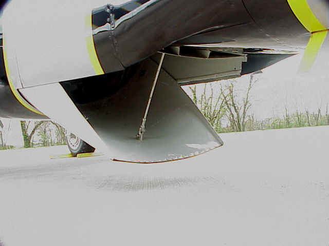
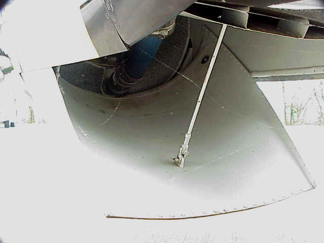
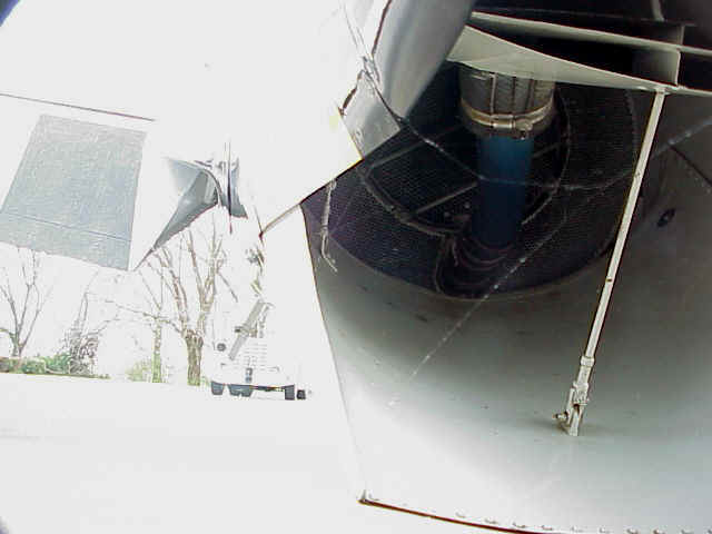
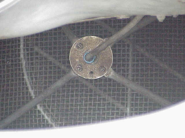
I received a call from Ed today from Flite Metal. He helped me get in touch with Kelvin at Keleo Creations. This guy manufactures scale exhaust for aircraft. You can find them on the web at http://www.keleo-creations.com/

He is going to manufacture a scale exhaust for the mustang and a scale intake manifold. I can take a Fuji 50 and turn it into a rear exhaust, rear intake engine. This gives me the opportunity to tuck the 50 inside the cowling.

The exhaust stacks will have flex tubing to a custom made exhaust canister mounted to the engine.

Ed also explained to me how to make an air induction duct to keep the engine cool with minimal weight that will also vent through the belly flaps just rear of the wing.

I have included pictures for review.

This is becoming a lot of fun guys. I can’t wait to get things rolling.

Attached Thumbnails Click image for larger version

Name:	Ay74131.jpg
Views:	31
Size:	22.0 KB
ID:	1275049   Click image for larger version

Name:	Vq50026.jpg
Views:	39
Size:	16.5 KB
ID:	1275050   Click image for larger version

Name:	Xc79513.jpg
Views:	40
Size:	20.6 KB
ID:	1275051  
Old 09-16-2009, 11:54 AM
  #43  
Condor060
Thread Starter
My Feedback: (2)
 
Condor060's Avatar
 
Join Date: Jun 2009
Location: Monroe, NC
Posts: 494
Likes: 0
Received 0 Likes on 0 Posts
Default RE: Byron 51 Build Thread

Hey Fellas, I sent an e-mail to JR, Spectrum, Futaba, and Hitec to find out what their recommendations would be for servos for the Byron 51. These are the responses I received. The Hitec flight package is around $1000.00. Seems a bit high for a flight package (not including any batteries) but I have no clue these days as to what is in the market and just how much I will have to spend to safely fly my 51. I don’t want to take the cheap route just to save money but I also don’t want to throw money away on something that is just overkill.
Would you mind giving me your opinions and recommendations for what I want to accomplish. The servo world has just gone off the edge and I can’t seem to find the answers I am looking for online. I didn’t realize so many different options existed. This is what happens when you take 15 years off from flying RC.
Thank you for any information you can provide.
JR SERVO PACKAGE
We would recommend the JRPS791 retract servo and no less than the JR
DS821 for the control surfaces.
The JR retracts are 4.8 volt only so if you run a 6 volt battery pack you will need
to run a regulator to an acceptable 5.2 volts.
Thanks,
Kory
Product Support Team Member
Horizon Hobby Distributors
4105 Fieldstone Road
Champaign, IL 61822
877-504-0233
SPECTRUM SERVO PACKAGE
Fred,
http://www.horizonhobby.com/Products/Default.aspx?ProdID=SPMSA6030 x 5 for Wings, Elevator, Rudder, and flaps.
Thanks,
Daniel
Product Support Team Member
Horizon Hobby Distributors
4105 Fieldstone Rd.
Champaign, IL 61822
877-504-0233
HITEC SERVO PACKAGE
Hello Fred,
(2) aileron servos- 7955TG re: titanium gears in the servo, titanium does not wear out, and are super strong.
(1) retract servo- 7985MG re: metal gears, programmable from 0 to 180degrees.
(1) flap servo- 7985mg re: metal gears, and programmable.
(1) throttle servo- 5245MG re: small, light, very popular throttle servo on gassers.
(1) rudder servo- 7955TG re: titanium gears, zero wear in gear train, lots of torque.
(1) elevator servo- 7955TG re: titanium gears, zero wear, lots of torque.
(1) tail retract servo- 7985MG re: metal gears, programmable.
All of these servos are programmable using any one of our servo programmers: HFP-20, HPP-21, and the HPP-21+. Using the programmer allows for precise set-up so that you do not run the risk of overloading the servo. Visit our website for our full line of products. www.hitecrcd.com
Thank you,
Billy Tompkins
Customer Service Rep.
Hitec RCD, LLC
Multiplex USA
Phone (858) 748- 8440
Fax (858) 859-2618
12115 Paine St.
Poway CA, 92064
Old 09-16-2009, 12:01 PM
  #44  
FliteMetal
 
FliteMetal's Avatar
 
Join Date: Oct 2002
Location: Houston, TX
Posts: 1,909
Likes: 0
Received 1 Like on 1 Post
Default RE: Byron 51 Build Thread

Fred:

Here is a cut and paste illustration of the flexible air duct utilized in automotive heat risers from the 60's and 70's.
Its still available in various diameters.

You open up the dump doors on the bottom of the air scoop and fuselage to permit air to vacate the engine area.
This solves the problem of an enclosed cowl on an inline engined model. I have edited the illustration to show the
exit fixture is constructed to attach to the light ply frame constructed for the rear dump door. The first one was a
little more than crude and probably confused some people... : )

Cheap to do and so easy...even a caveman can do it.... ;^)


Here is one style of flexible duct from the TransAm These are available in various sizes and wire hoops per inch.


Old 09-16-2009, 12:25 PM
  #45  
Condor060
Thread Starter
My Feedback: (2)
 
Condor060's Avatar
 
Join Date: Jun 2009
Location: Monroe, NC
Posts: 494
Likes: 0
Received 0 Likes on 0 Posts
Default RE: Byron 51 Build Thread

Ok, now thats about the coolest thing I have ever seen. After I finish eatting some mammal flesh and learn how to make fire I will have to draw this on my cave wall to see if it works. I like it Ed. Thanks very much.
Old 09-16-2009, 01:53 PM
  #46  
masteromodels
My Feedback: (11)
 
Join Date: Apr 2002
Location: north port, FL
Posts: 731
Likes: 0
Received 0 Likes on 0 Posts
Default RE: Byron 51 Build Thread

Hey Condor the original byron P-51's actually used standard servos from way back then a lot of todays equipment is great but a lot of overkill. In my new BYRON P-51 I will be usung all FUTABA 3305 servos for the elevator, in fact I' am changing it to a center rod for the elev. so it does not show, also 3305's for the airleons and flaps and rudder then 3004s for the throttle and tank drops. The retract servo is still up in the air . I might use a 3004 for the retract if I use the up valve, but I still use the old original byron (ACE) 7 second servo and dual spool valve in my old P-51 and I never have had any problems with it, not bad for over 13yrs. I still have both valves so I' am still undecided. You can use any servos you want, if you feel confortable with the digital or higher end analog servos you can use them also. My old one has the old FUTABA quater scale servos for the flaps and airleons and elevator and standard servos for the rest except the retract. The FUTABA 3305 servos have plenty of torque to handle the BYRON P-51 with dual ball bearings and netal gears. This is just my opinion. Oh I also saw a sale on the 3305's some where it might pay to check it out and they will not break the bank.


thanks bob
Old 09-16-2009, 02:36 PM
  #47  
FliteMetal
 
FliteMetal's Avatar
 
Join Date: Oct 2002
Location: Houston, TX
Posts: 1,909
Likes: 0
Received 1 Like on 1 Post
Default RE: Byron 51 Build Thread

Fred:


Here is the piece you construct from G-10 and 1/2 (size was used only to show placement of the side balsa) square stick to mount just ahead of the rear dump door hinge point. Hot air from the engine exits through the top... Cold air from the belly scoop flows through and out the bottom slot. The actual air slot space should be as tall as permissable to scavage the most air.

Attached Thumbnails Click image for larger version

Name:	Ca81092.jpg
Views:	25
Size:	28.2 KB
ID:	1276585   Click image for larger version

Name:	Yt63124.jpg
Views:	28
Size:	48.3 KB
ID:	1276586  
Old 09-16-2009, 09:56 PM
  #48  
Condor060
Thread Starter
My Feedback: (2)
 
Condor060's Avatar
 
Join Date: Jun 2009
Location: Monroe, NC
Posts: 494
Likes: 0
Received 0 Likes on 0 Posts
Default RE: Byron 51 Build Thread

For those that can't see the picture of the cooling ducts for the P-51
Attached Thumbnails Click image for larger version

Name:	Bz78345.jpg
Views:	33
Size:	64.5 KB
ID:	1276826  
Old 09-17-2009, 09:50 AM
  #49  
FliteMetal
 
FliteMetal's Avatar
 
Join Date: Oct 2002
Location: Houston, TX
Posts: 1,909
Likes: 0
Received 1 Like on 1 Post
Default RE: Byron 51 Build Thread

Sometimes your version of IE will not render graphics posts when sites initially load. When you see an X instead of the image you will find the circumstance will be remedied by simply refreshing your screen....by clicking the green up and down button next to the X in the heading of your browser...
Old 09-17-2009, 10:39 AM
  #50  
FliteMetal
 
FliteMetal's Avatar
 
Join Date: Oct 2002
Location: Houston, TX
Posts: 1,909
Likes: 0
Received 1 Like on 1 Post
Default RE: Byron 51 Build Thread

I'll add this then back out of here so you can get on with showing your build... For those who have never seen what is up inside of the dump door on the A-36 or P-51 here's a closer look... ; )

Now...we return you to Fred's build.... ;^)


Contact Us - Archive - Advertising - Cookie Policy - Privacy Statement - Terms of Service -

Copyright © 2024 MH Sub I, LLC dba Internet Brands. All rights reserved. Use of this site indicates your consent to the Terms of Use.