


LOCKHEED P-38J “LIGHTNING”. A giant 1/4 scale scratch built model
 01-30-2019, 11:48 AM
#76

Thread Starter

Join Date: Oct 2012
Location: ZARAGOZA, SPAIN
Posts: 97
Likes: 0
Received 0 Likes
on
0 Posts
Finishing and painting
The model has been coated with 0,8818 oz (25 g) of fiberglass, which improves its structural strength and softens imperfections.
Fortunately, we should not worry about getting a "mirror" finishing of the surface, since, according to the sources consulted, the P-38 showed quite irregularity in the coating panels, the result of manual shaping and use. So, with a few water sanding passes the surface will be ready for treatment.
The last layer of resin is applied somewhat more generously in order to allow the carving of its surface with a calibrated ceramic cutter, simulating the joints of the panels.

A cheap device used to easily cut cellophane seals without damaging the containers, which can be purchased in stationery stores. This is the carving tool to make the joints panels.
Just to draw with a hard pencil the lines through which the joints of the panel pass, to lean on a ruler and to slide the cutter over them, "biting" a few tenths of the layer of resin. The result is good enough.
The model has been coated with 0,8818 oz (25 g) of fiberglass, which improves its structural strength and softens imperfections.
Fortunately, we should not worry about getting a "mirror" finishing of the surface, since, according to the sources consulted, the P-38 showed quite irregularity in the coating panels, the result of manual shaping and use. So, with a few water sanding passes the surface will be ready for treatment.
The last layer of resin is applied somewhat more generously in order to allow the carving of its surface with a calibrated ceramic cutter, simulating the joints of the panels.
A cheap device used to easily cut cellophane seals without damaging the containers, which can be purchased in stationery stores. This is the carving tool to make the joints panels.
Just to draw with a hard pencil the lines through which the joints of the panel pass, to lean on a ruler and to slide the cutter over them, "biting" a few tenths of the layer of resin. The result is good enough.
 02-15-2019, 09:51 AM
#77
Thread Starter
Join Date: Oct 2012
Location: ZARAGOZA, SPAIN
Posts: 97
Likes: 0
Received 0 Likes
on
0 Posts
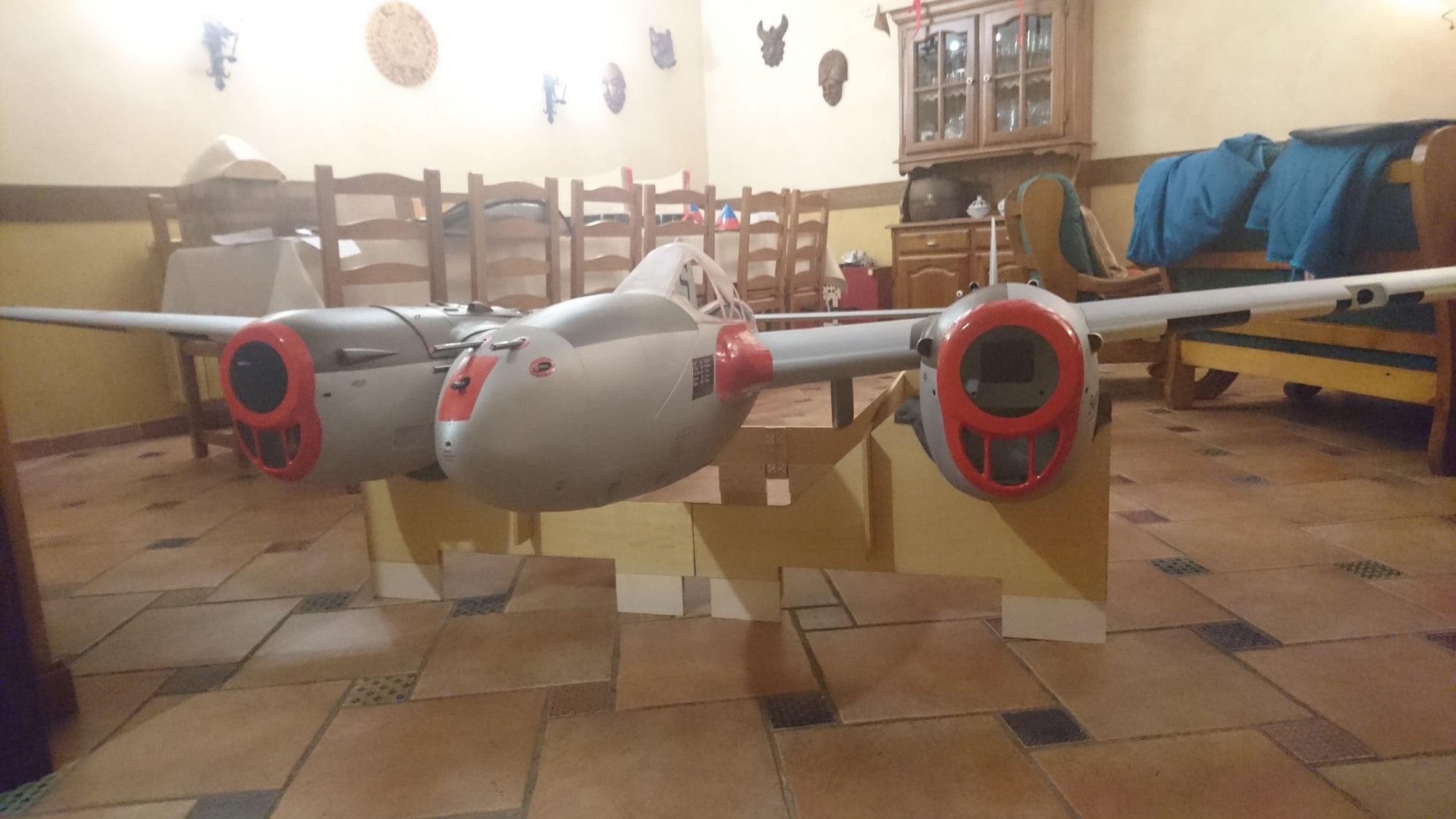
The P-38 had a natural aluminum paneling with some parts of steel, so getting this finish is not easy. We must avoid the attractive "shiny silver" finish that, in my opinion, leaves an unrealistic metallic surface (unless we want to reproduce the flashing P-38 of the sponsored Red Bull, of course).
Due to my inexperience with the use of coatings type Flite-Metal® or Aero-Foil®, I opted for the use of automotive metallic paint and can, thus, reproduce the flush rivets "almost like real" (those applied on those metallic coatings seem to be slightly low relief, which is not correct for this model).
The multiple access covers are made from very thin self-adhesive printer film, applied after the first layer of primer, which is previously sanded to reveal and correct imperfections. Two additional primer layers have been applied and painted with metallic Besa-Val 6021® satin "white aluminum" system (RAL 9006), which provides a very strong natural aluminum finish, especially if we shade it with sandpaper of 2000 grain.
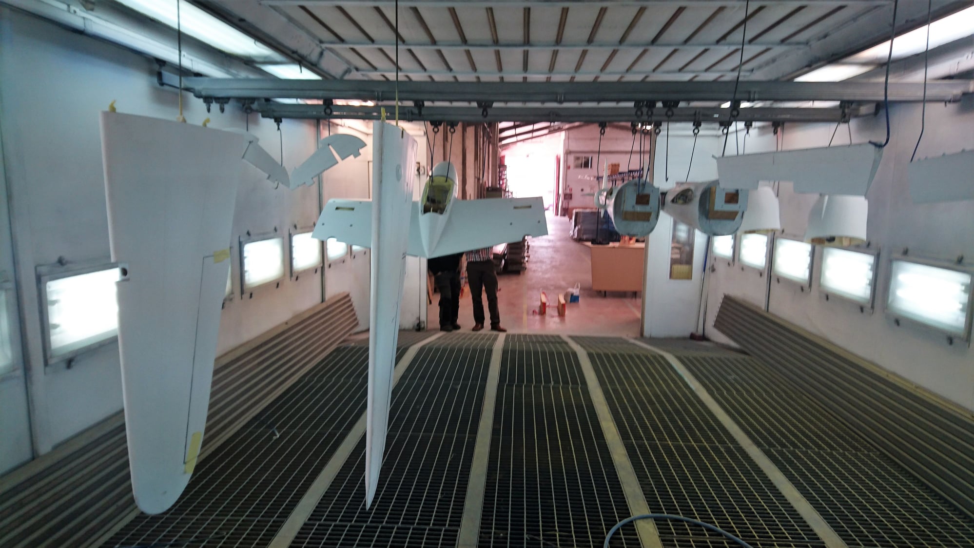
Thanks to my friend Alberto Barrios, I could do the painting personally on a professional paint booth. A great chance at my fingertips.
Due to my inexperience with the use of coatings type Flite-Metal® or Aero-Foil®, I opted for the use of automotive metallic paint and can, thus, reproduce the flush rivets "almost like real" (those applied on those metallic coatings seem to be slightly low relief, which is not correct for this model).
The multiple access covers are made from very thin self-adhesive printer film, applied after the first layer of primer, which is previously sanded to reveal and correct imperfections. Two additional primer layers have been applied and painted with metallic Besa-Val 6021® satin "white aluminum" system (RAL 9006), which provides a very strong natural aluminum finish, especially if we shade it with sandpaper of 2000 grain.
Thanks to my friend Alberto Barrios, I could do the painting personally on a professional paint booth. A great chance at my fingertips.
02-27-2019, 02:42 AM
#78
Thread Starter
Join Date: Oct 2012
Location: ZARAGOZA, SPAIN
Posts: 97
Likes: 0
Received 0 Likes
on
0 Posts
Hi everybody:
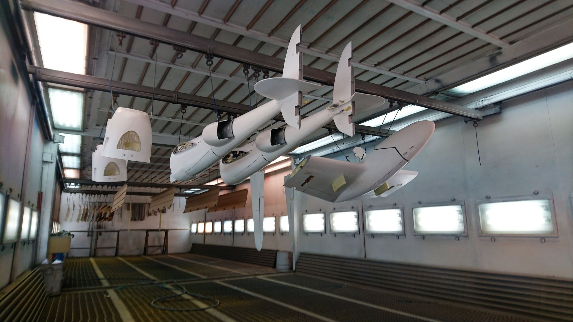
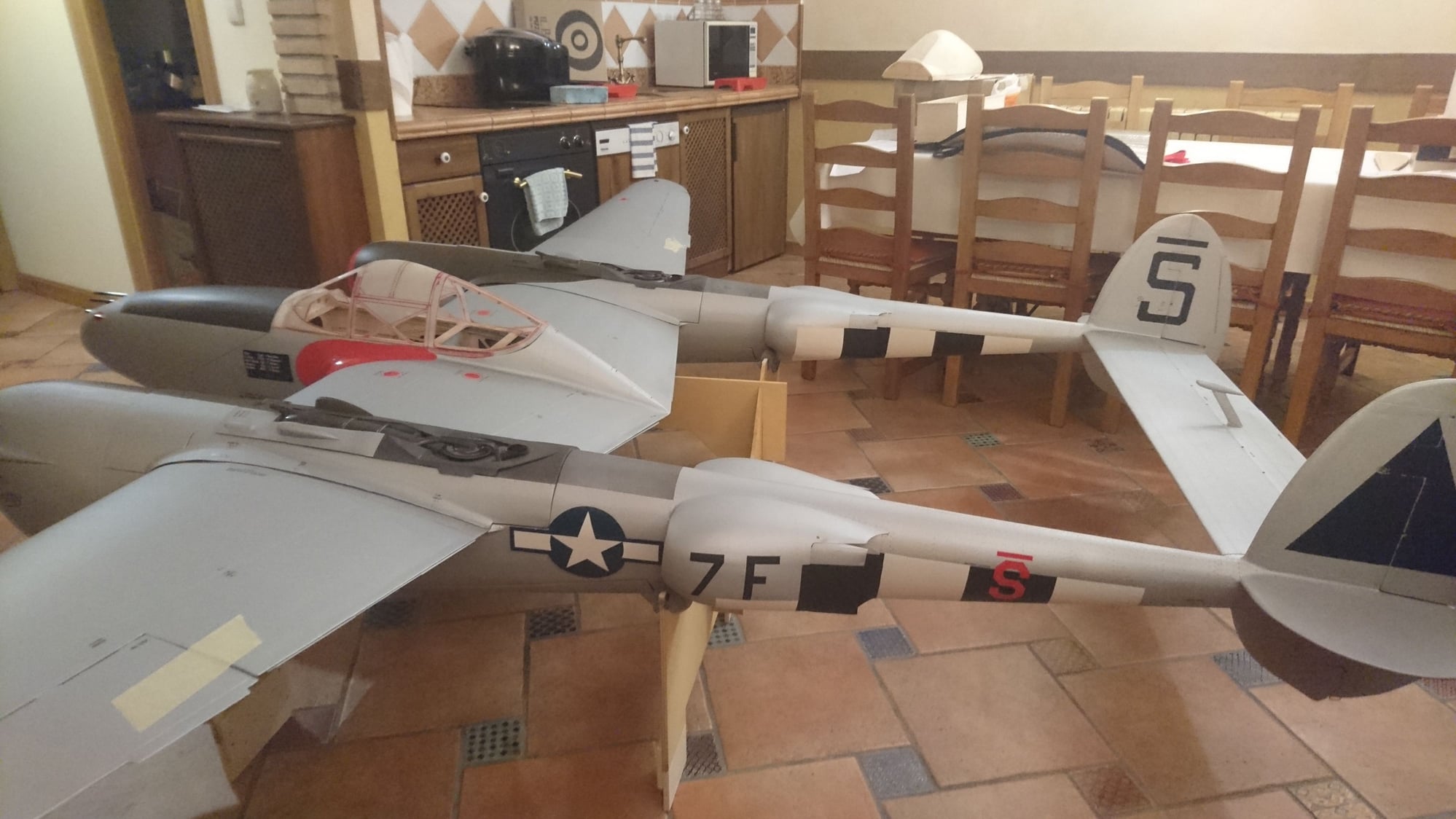
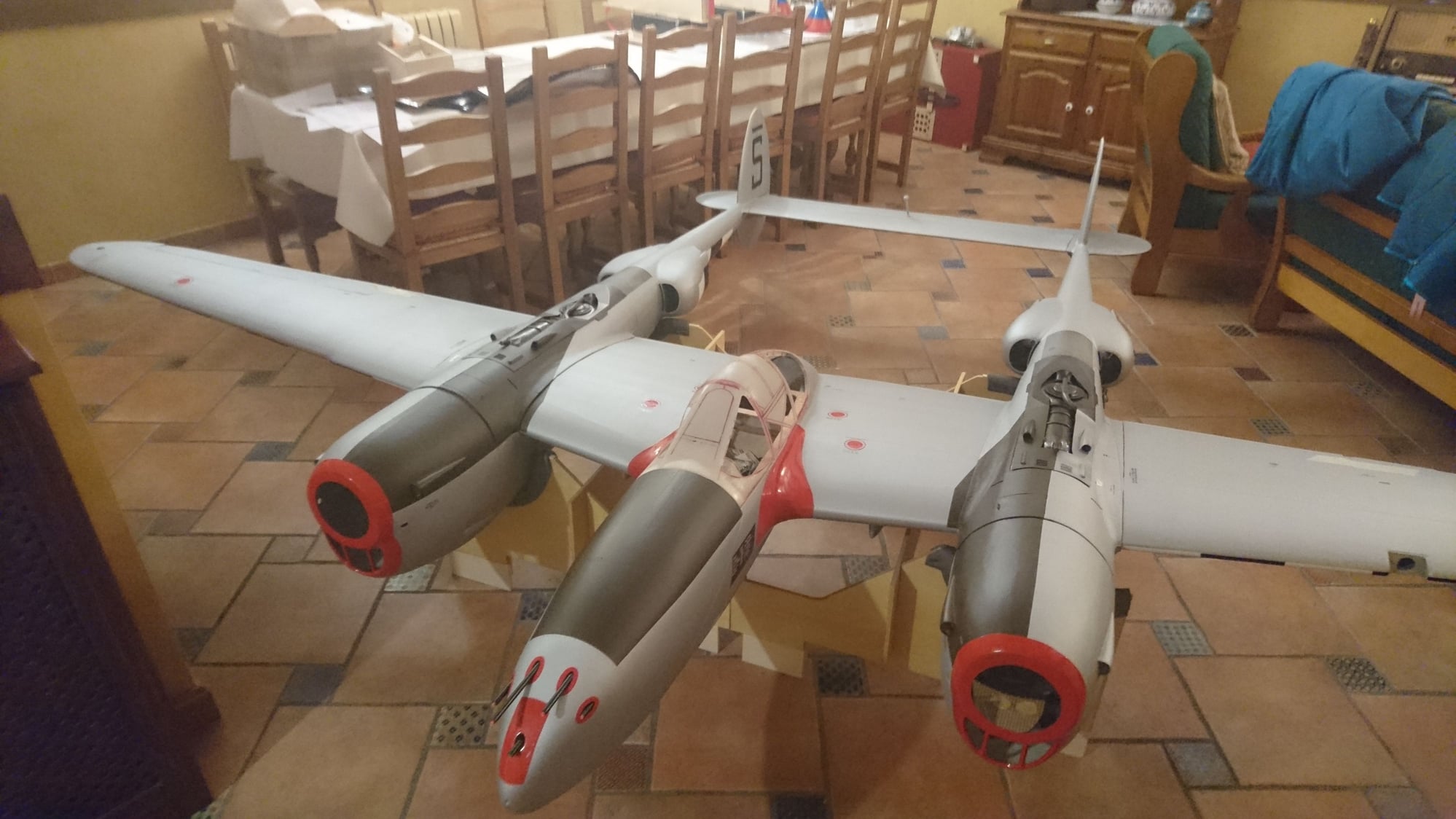
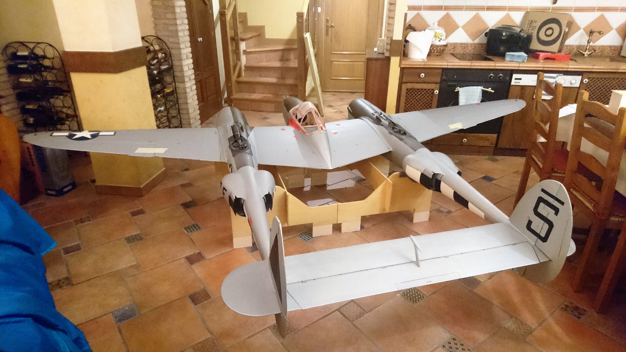
I apologize I had forgotten to insert this pair of pics of the fully primed model, before transporting to the painting booth.
The primer (Valentine Valtodo®) has been applied entirely by roller, with three intermediate sanding.
I apologize I had forgotten to insert this pair of pics of the fully primed model, before transporting to the painting booth.
The primer (Valentine Valtodo®) has been applied entirely by roller, with three intermediate sanding.
03-11-2019, 09:10 AM
#79
Thread Starter
Join Date: Oct 2012
Location: ZARAGOZA, SPAIN
Posts: 97
Likes: 0
Received 0 Likes
on
0 Posts
The simulation of flush rivets was a meticulous challenge. They were made with brass tube of different diameter, like a punch, with very sharp edge and coupled to the tip of a 15W electronic soldering iron.
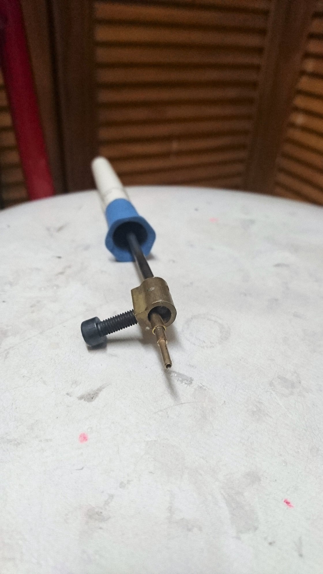
A slight press and the heat literally fuses the paint, leaving the rivet ring slightly marked without relief.
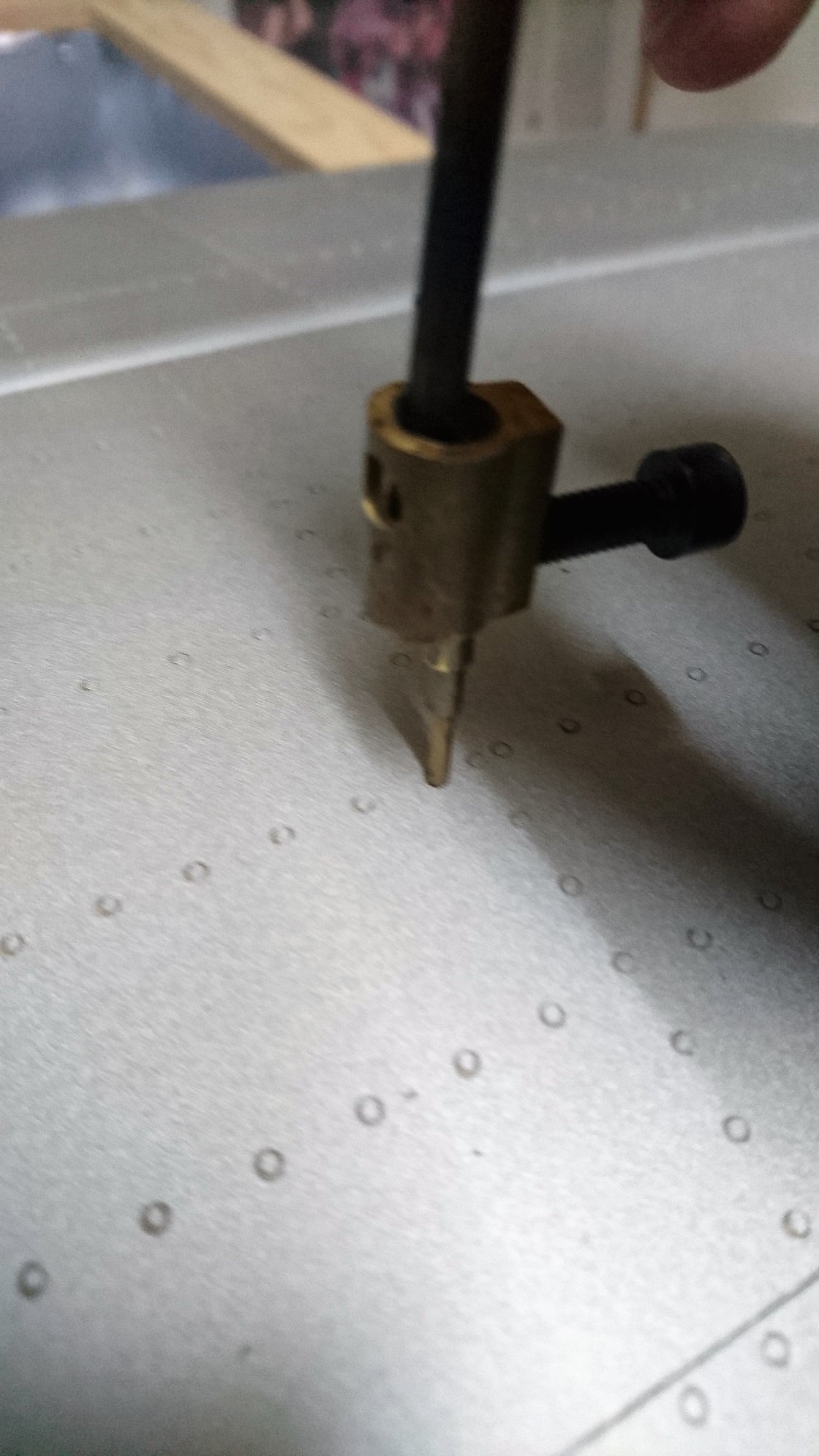
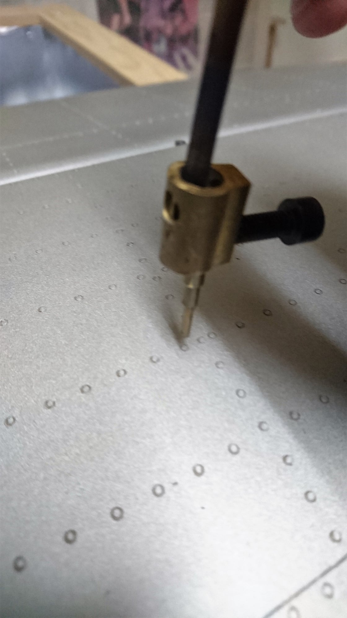
The central groove, in the fastener type, is achieved with the fine hot tip of a precision screwdriver applied inside the marked ring.
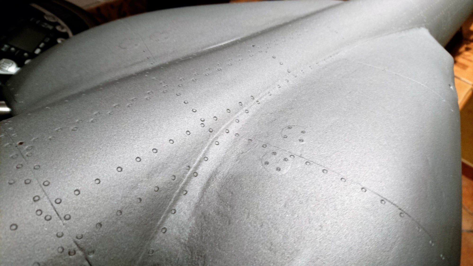
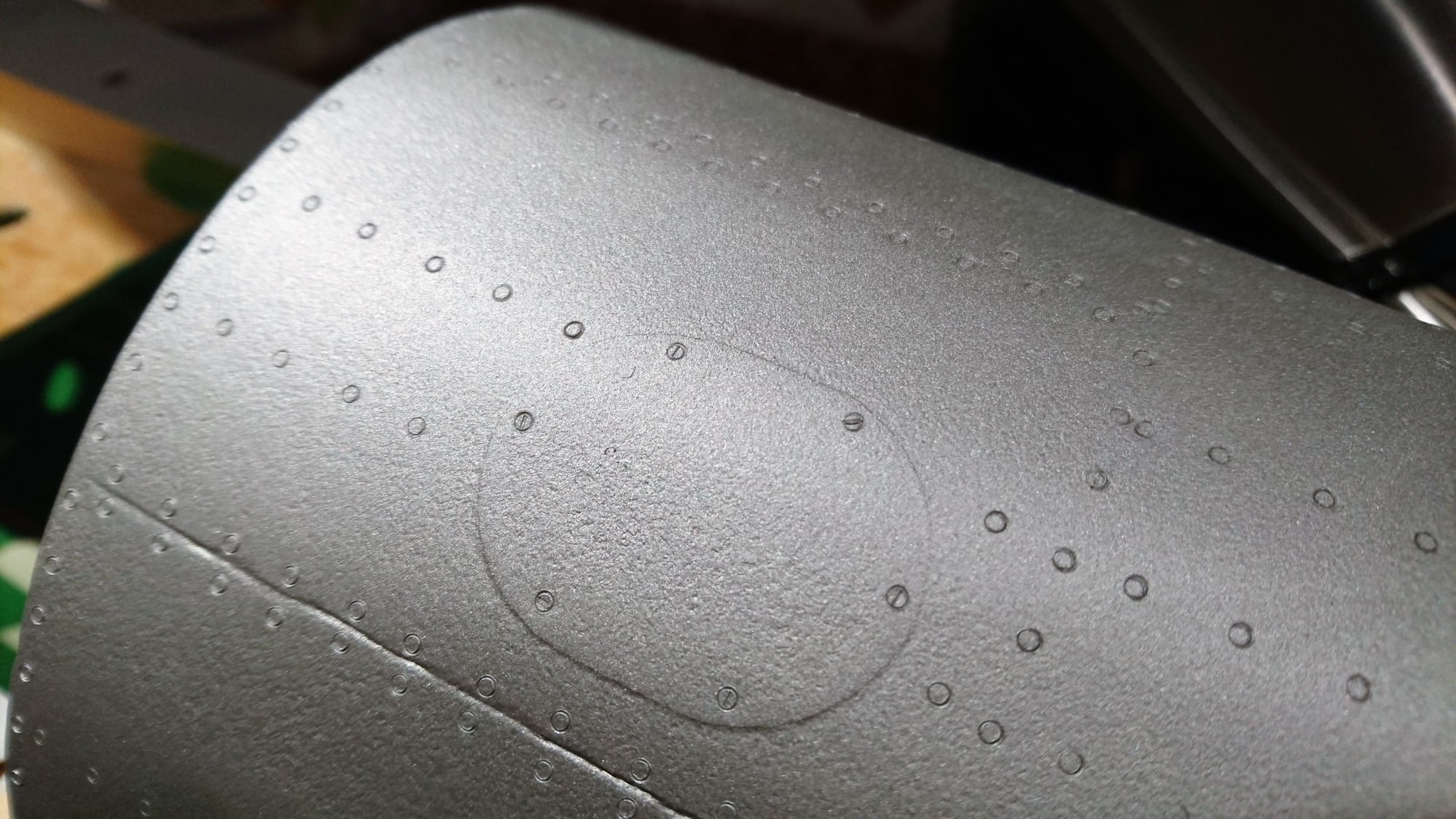
With a no trembled pulse and a large dose of patience to simulate more than 65,000 rivets that the model carries, a very realistic result is obtained; in fact, it is not possible to appreciate them if we go further than 10 ft but they are clearly visible at a closer distance.
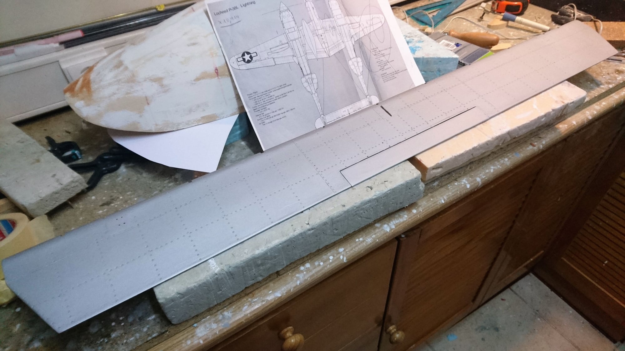
With the reference close to me all the time
A slight press and the heat literally fuses the paint, leaving the rivet ring slightly marked without relief.
The central groove, in the fastener type, is achieved with the fine hot tip of a precision screwdriver applied inside the marked ring.
With a no trembled pulse and a large dose of patience to simulate more than 65,000 rivets that the model carries, a very realistic result is obtained; in fact, it is not possible to appreciate them if we go further than 10 ft but they are clearly visible at a closer distance.
With the reference close to me all the time
03-27-2019, 02:47 AM
#80
Thread Starter
Join Date: Oct 2012
Location: ZARAGOZA, SPAIN
Posts: 97
Likes: 0
Received 0 Likes
on
0 Posts
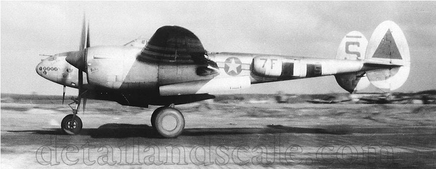
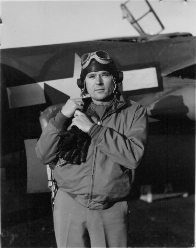
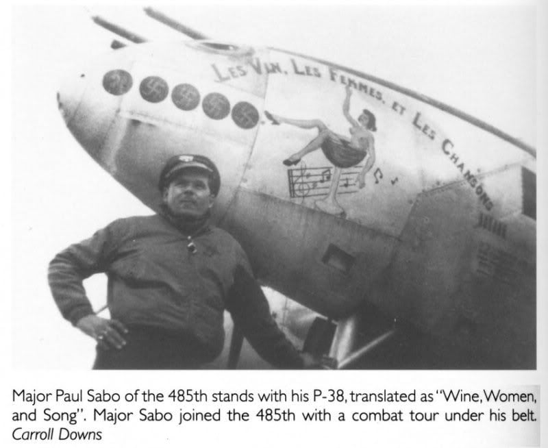
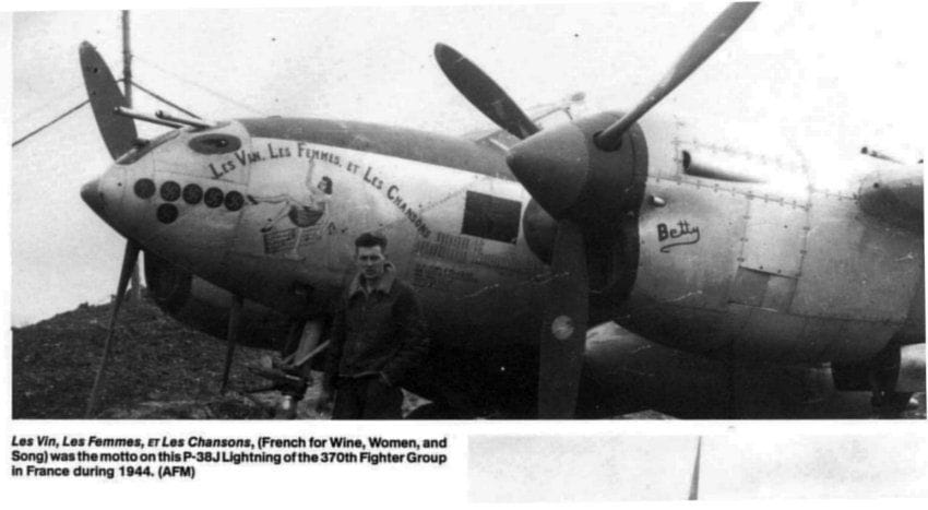
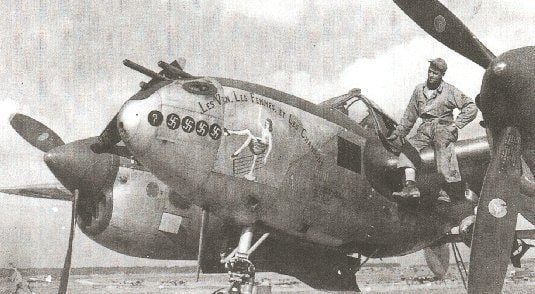
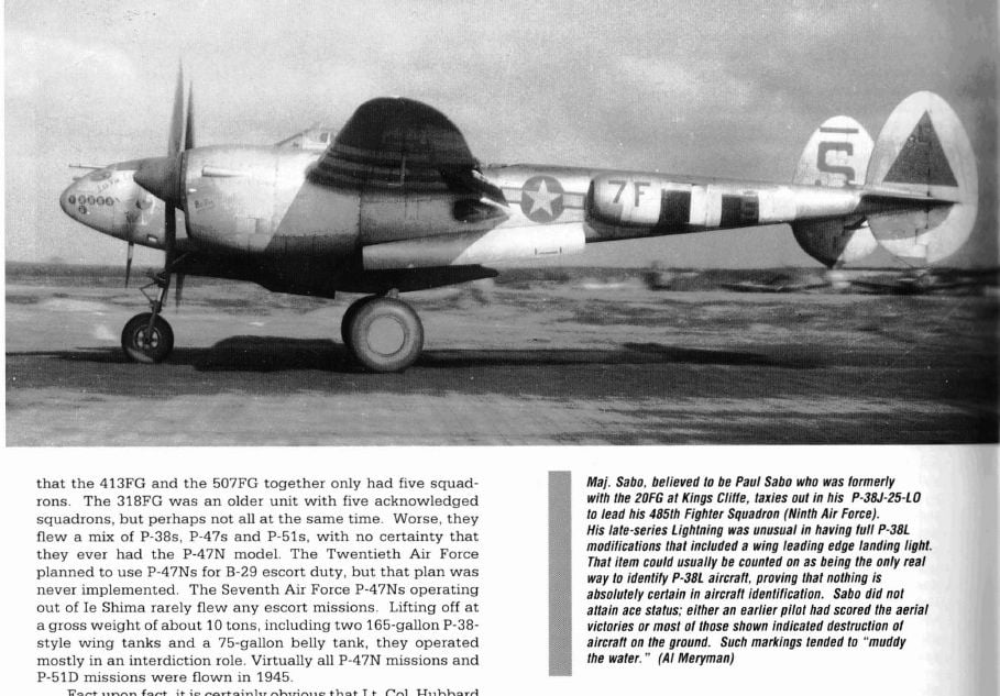
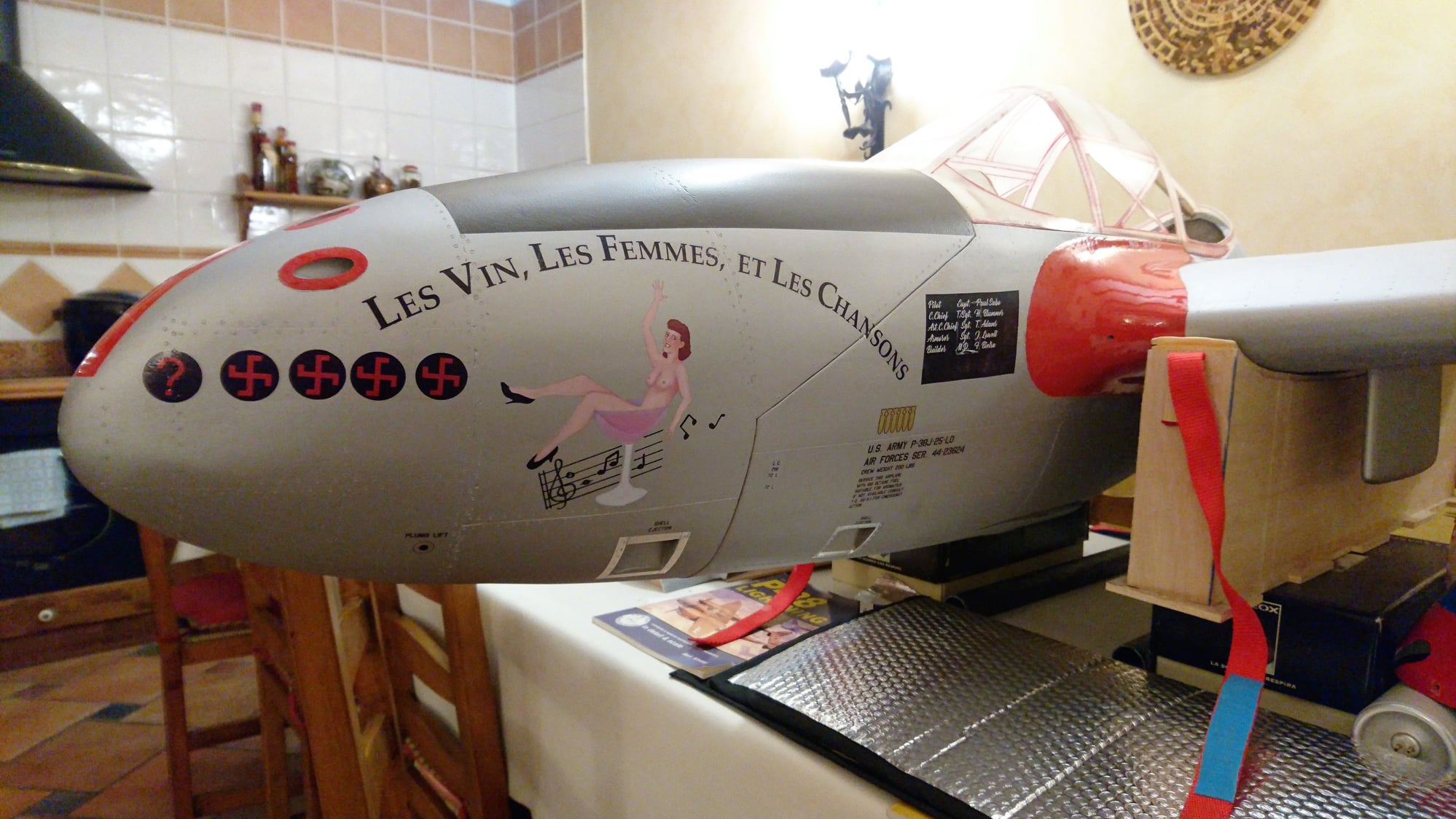
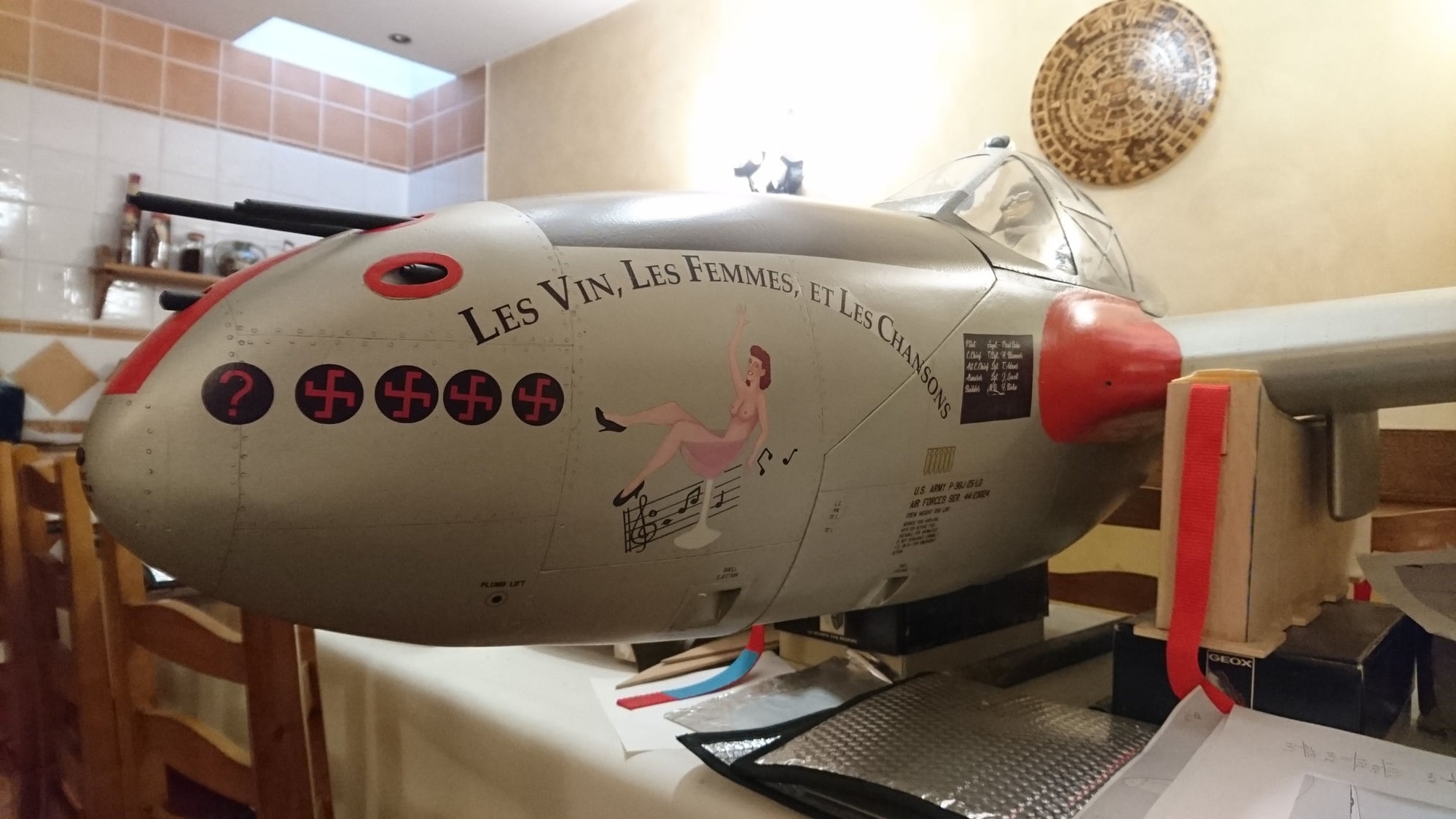
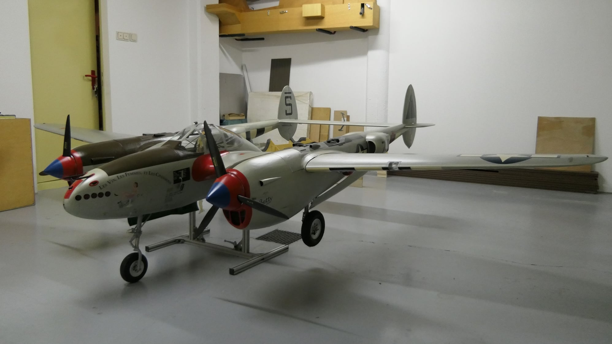
The reproduced model is a P-38J-25-LO (44-23624) (485th FS/370th FG) that was based in Florennes (Belgium) on September 1944, flown by then captain Paul J. Sabo during the Allied invasion of Normandy. Being a 25-LO, she was one of the 210 "J" that had recovery flaps and landing light on the leading edge of the left wing, so, externally, it was indistinguishable from the P-38 L.
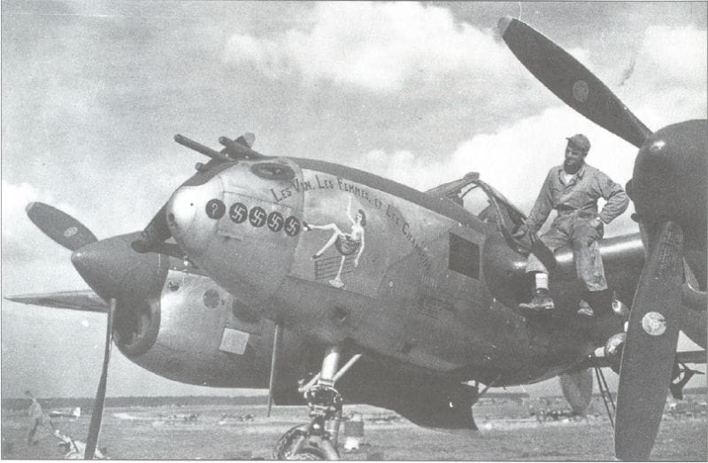
I have chosen it for its colorful decoration and particular nose’s pin-up, that frivolously reflects the triumphalist feeling of Operation Overlord: a label "Les vin, les femmes et les chansons" (wine, women and songs) heading to "Betty", a suggestive young lady in a happy and carefree attitude. An “appetizing” challenge to reproduce.
I have chosen it for its colorful decoration and particular nose’s pin-up, that frivolously reflects the triumphalist feeling of Operation Overlord: a label "Les vin, les femmes et les chansons" (wine, women and songs) heading to "Betty", a suggestive young lady in a happy and carefree attitude. An “appetizing” challenge to reproduce.
04-09-2019, 09:04 AM
#81
Thread Starter
Join Date: Oct 2012
Location: ZARAGOZA, SPAIN
Posts: 97
Likes: 0
Received 0 Likes
on
0 Posts
I have reproduced the marking of the nose according to documentation that shows four recognized enemy victories and one doubtful (later reports show a greater amount of victories).

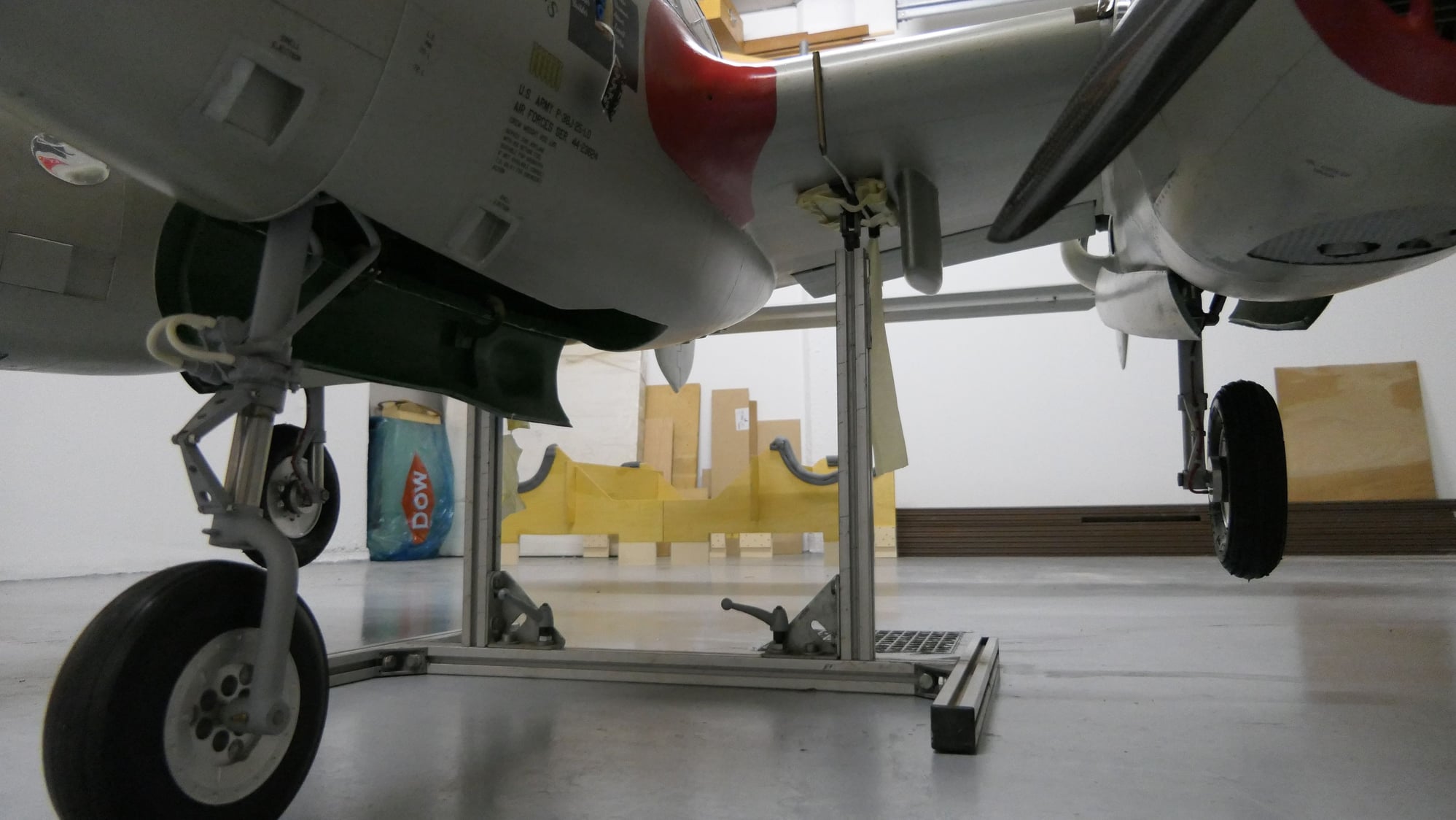
The colour of nacelle’s fillet and outboard superchargers air intake is controversial and not possible to clarify in this model; may be the same red one (RAL 3020 ) or blue (RAL 5002) of the prop spinner, even some people reproduce it in black, which does not seem correct. I decided on red, judging by the opinion of many and the colour tests of the contemporary snapshots.
Hard to know the fillet color
Look at the marking of the superchargers air intake
The antiglare painting over the gondola and fuselages is Olive Drab" (RAL 6022), which is the more often described by most erudites, although it is not uncommon to find references in black. The badges and bigger inscriptions have been painted using hand-cut vinyl stencils, while the nose art and little inscriptions have been made by printing on decal paper and subsequent transferring.
Hand made drawing files
The superchargers and their fairings have been decorated in Metal Color Vallejo® metallic acrylics (77712, 77721 and 77723). For the interior of cockpit and landing gear, I used matte acrylic "interior green" ANA 611 (FS 34151).
04-22-2019, 08:22 AM
#82
Thread Starter
Join Date: Oct 2012
Location: ZARAGOZA, SPAIN
Posts: 97
Likes: 0
Received 0 Likes
on
0 Posts
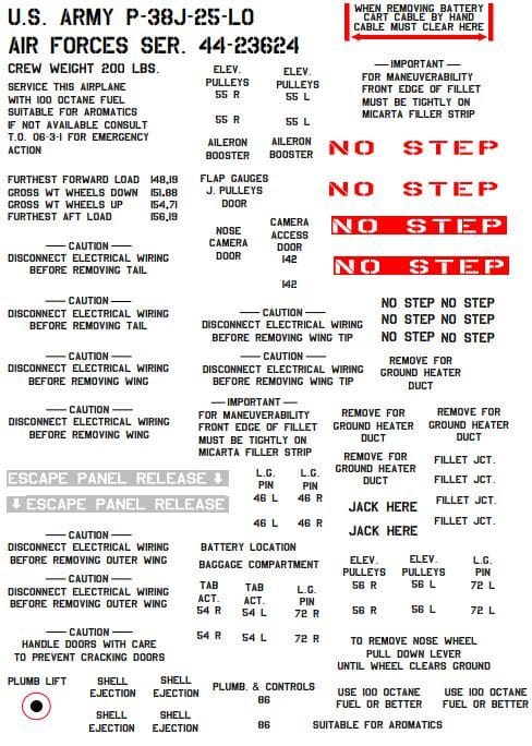
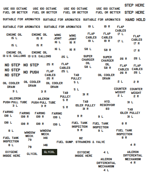
Anecdotally, I was lucky enough to contact an experienced static modeler, Luca Pennacchietti, who, providentially, sold a set of laser-printed decals with the precise inscriptions for this peculiar model, but yes, for static models 1/18!
Once explained my project, he was enthusiastic and did not mind to give me the computer file of his property to maximize and print to the desired size, with the only condition of sending him some pics of the final result.
When I received it, the file not only contained the set of inscriptions and badges of the plane with the detail of its location, but the USAAF font type and the pin-up drawing of the suggestive Betty, of course.

Due to the low resolution of this one, I had to redraw completely to correct the scale factor imperfections; I also had to supplement several inscriptions by consulting the bibliography, but his initial assignment was very helpful. Thanks, Luca!
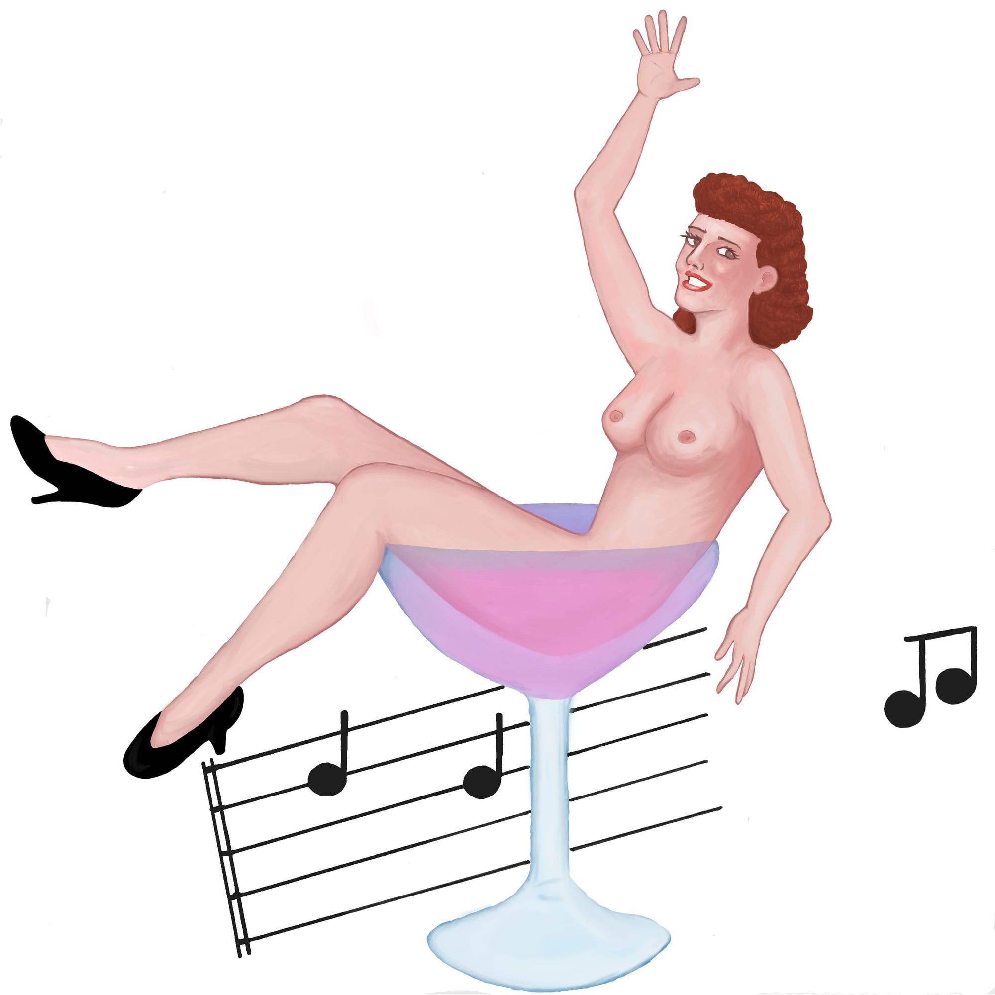
Redrawing Betty!
Once explained my project, he was enthusiastic and did not mind to give me the computer file of his property to maximize and print to the desired size, with the only condition of sending him some pics of the final result.
When I received it, the file not only contained the set of inscriptions and badges of the plane with the detail of its location, but the USAAF font type and the pin-up drawing of the suggestive Betty, of course.
Due to the low resolution of this one, I had to redraw completely to correct the scale factor imperfections; I also had to supplement several inscriptions by consulting the bibliography, but his initial assignment was very helpful. Thanks, Luca!
Redrawing Betty!
05-13-2019, 08:14 AM
#83
Thread Starter
Join Date: Oct 2012
Location: ZARAGOZA, SPAIN
Posts: 97
Likes: 0
Received 0 Likes
on
0 Posts
The model has been aged and weathered by highlighting the joints of the panels with 2H and 4H pencils, diffusing surfaces with graphite powder and dry brush techniques, here and there, coating the whole surface with a final layer of transparent matte polyurethane varnish to soften the marking and the brightness of the decals.
Contrary my usual procedure, for the maiden flight I have only enabled the pilot, his seat and the upper cover of the instrument panel, conditioning the execution of the laborious cockpit to check the correct operation of all systems, flight and landing. If everything turns out to be as expected, doing the instrumentation later will be plain sailing. I apologize for this concession but, when is a model ever finished?
Contrary my usual procedure, for the maiden flight I have only enabled the pilot, his seat and the upper cover of the instrument panel, conditioning the execution of the laborious cockpit to check the correct operation of all systems, flight and landing. If everything turns out to be as expected, doing the instrumentation later will be plain sailing. I apologize for this concession but, when is a model ever finished?
07-24-2019, 06:08 AM
#86
Thread Starter
Join Date: Oct 2012
Location: ZARAGOZA, SPAIN
Posts: 97
Likes: 0
Received 0 Likes
on
0 Posts
Hello again:
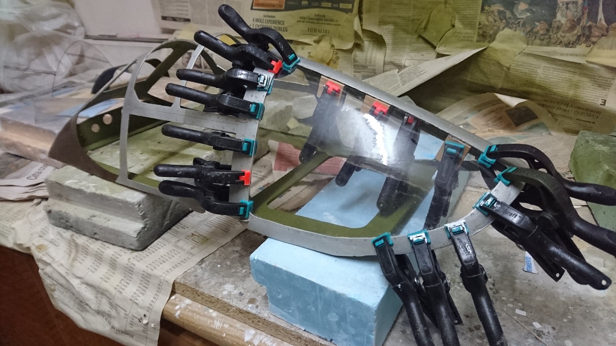
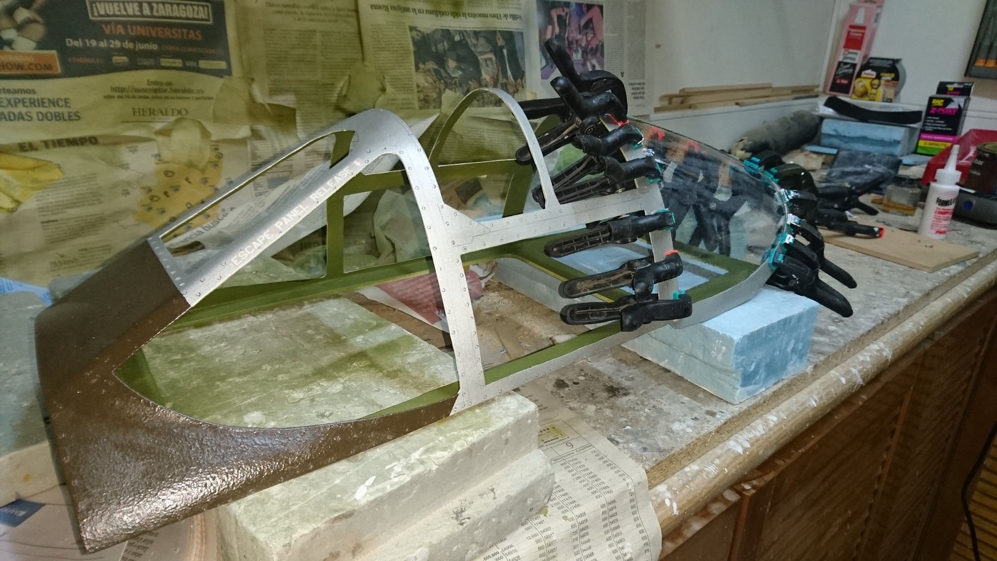
After a few weeks of inactivity in the forum, I can finally show the first results of the conformation of the glass of the cabin.
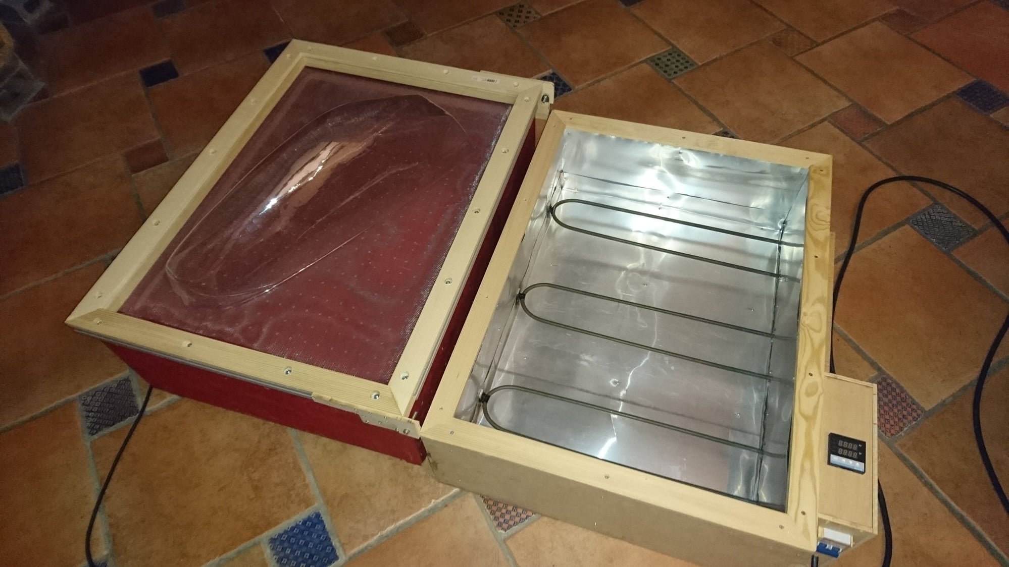
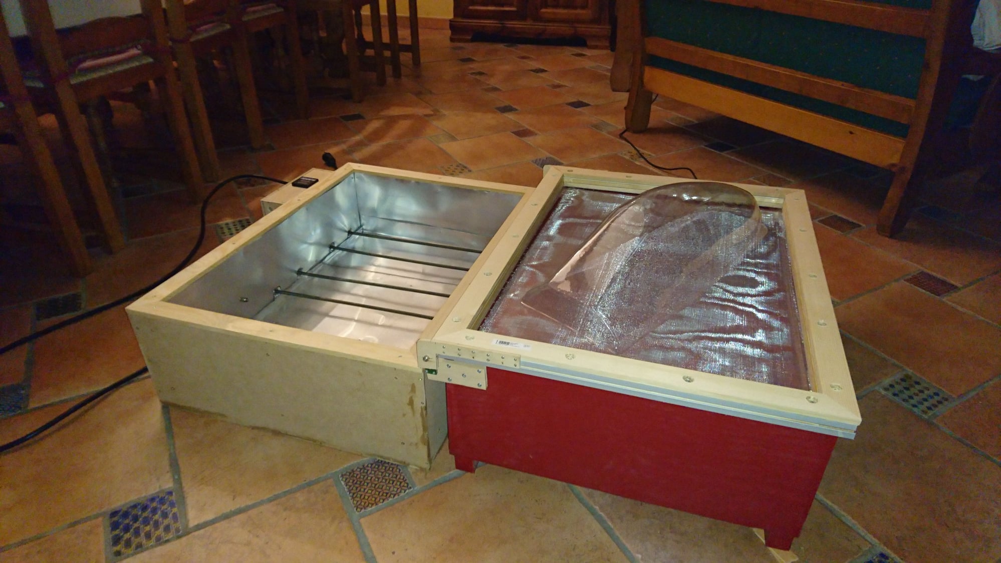
As I said, I had to manufacture a thermo-forming machine of considerable dimensions in two modules, the thermofusion one of the acetate sheet (actually 0.8 mm PVC) and the aspiration one.
The first is an insulated wooden drawer with 3 cm thick glass wool and covered with 0.6 mm aluminum sheet. It carries 3 resistors of 1000W each, controlled by a PID (REX C100), K type thermocouple and a solid state relay.
The second is an airtight drawer with two powerful home vacuum engines, as is logical, multi-perforated by the suction upper side.
The frame of the sheet consists of two frames of reinforced wood with an aluminum profile and pivots on one axis on one of the drawers (in my case the one for vacuuming).
The process is the same as always, the sheet is heated to the optimum point (in this case at 170ş C) and quickly collapsed on the mold that is waiting, already preheated, in the vacuum drawer. The aspiration is immediately activated for a few seconds.
The result is what you can see in the photos.
After a few weeks of inactivity in the forum, I can finally show the first results of the conformation of the glass of the cabin.
As I said, I had to manufacture a thermo-forming machine of considerable dimensions in two modules, the thermofusion one of the acetate sheet (actually 0.8 mm PVC) and the aspiration one.
The first is an insulated wooden drawer with 3 cm thick glass wool and covered with 0.6 mm aluminum sheet. It carries 3 resistors of 1000W each, controlled by a PID (REX C100), K type thermocouple and a solid state relay.
The second is an airtight drawer with two powerful home vacuum engines, as is logical, multi-perforated by the suction upper side.
The frame of the sheet consists of two frames of reinforced wood with an aluminum profile and pivots on one axis on one of the drawers (in my case the one for vacuuming).
The process is the same as always, the sheet is heated to the optimum point (in this case at 170ş C) and quickly collapsed on the mold that is waiting, already preheated, in the vacuum drawer. The aspiration is immediately activated for a few seconds.
The result is what you can see in the photos.
08-01-2019, 08:54 AM
#87
Thread Starter
Join Date: Oct 2012
Location: ZARAGOZA, SPAIN
Posts: 97
Likes: 0
Received 0 Likes
on
0 Posts
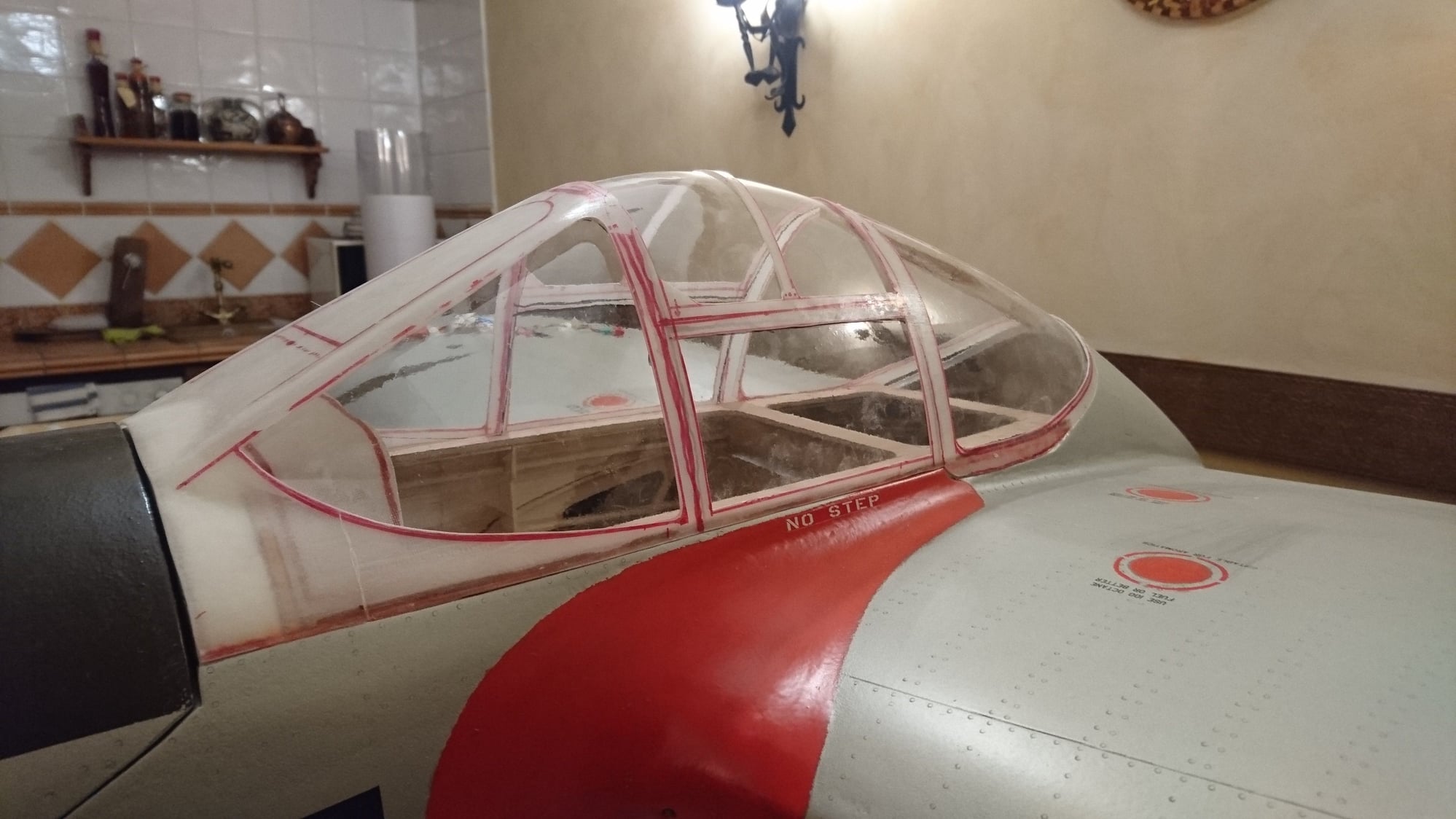
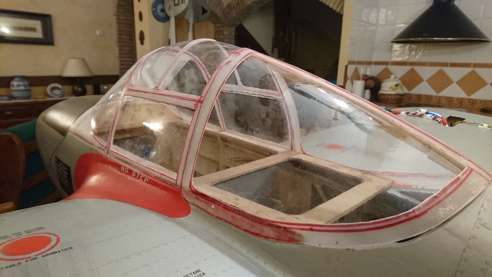
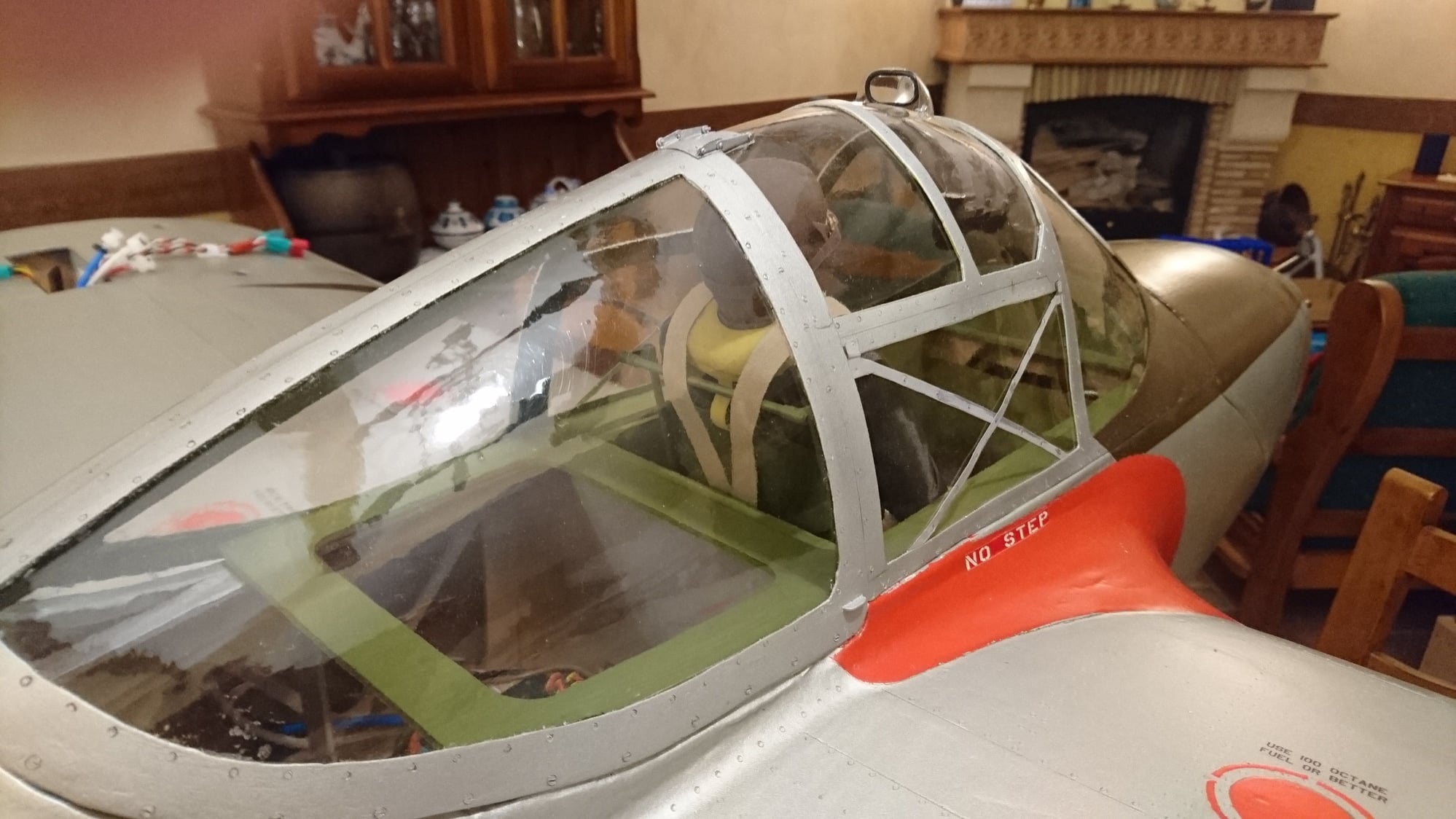
The structure of the canopy has been fenestrated (made of fiber with the same mold that I used for glassware), to fit the glasses and verify their correct position.
The goal is to glue them with special glue for canopy and place the interior frames with all the original screws and rivets.
08-21-2019, 07:38 AM
#88
Thread Starter
Join Date: Oct 2012
Location: ZARAGOZA, SPAIN
Posts: 97
Likes: 0
Received 0 Likes
on
0 Posts
Back after a few days of deserved family rest.
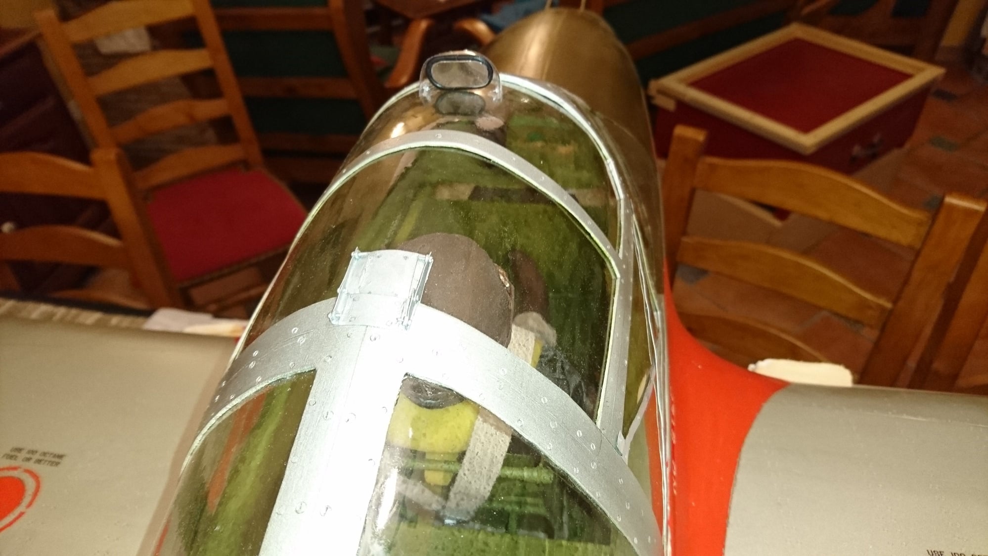
Once the canopy framework is painted, the different rivets and screws are made according to the original plan, using the same method described for the aircraft.
Then, carefully, glasses are glued one by one. In my case, I used Pacer® Formula 560 glue.
Once the canopy framework is painted, the different rivets and screws are made according to the original plan, using the same method described for the aircraft.
Then, carefully, glasses are glued one by one. In my case, I used Pacer® Formula 560 glue.
09-03-2019, 01:58 AM
#89
Thread Starter
Join Date: Oct 2012
Location: ZARAGOZA, SPAIN
Posts: 97
Likes: 0
Received 0 Likes
on
0 Posts
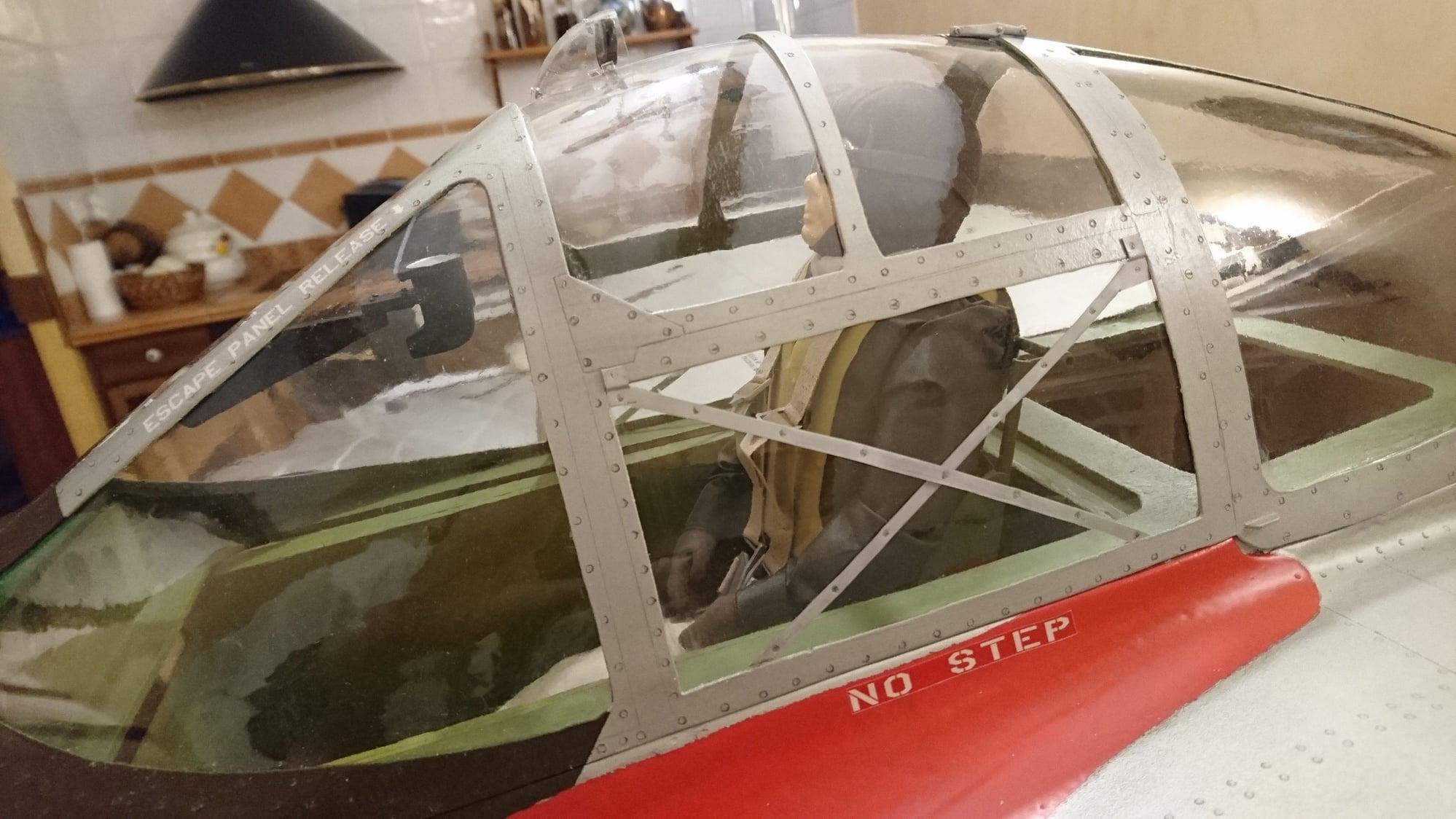
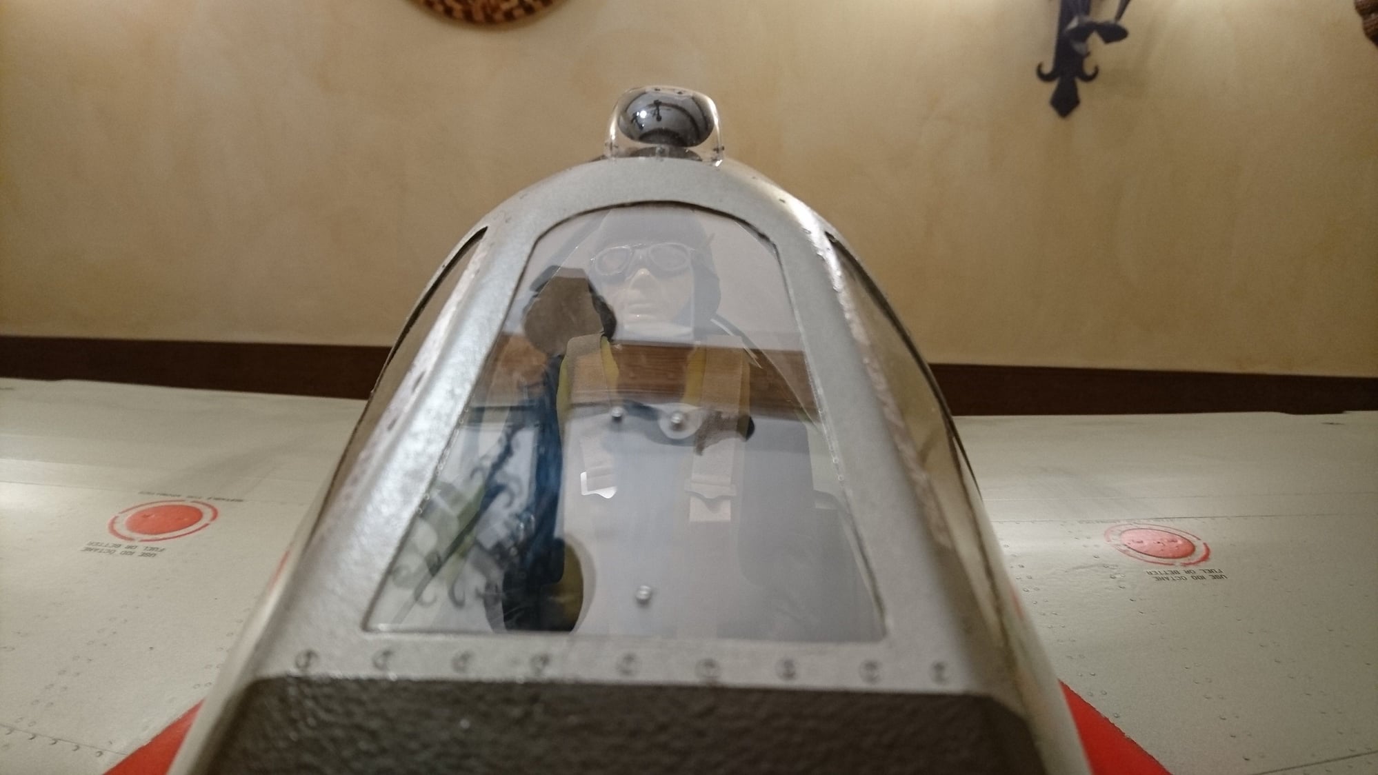
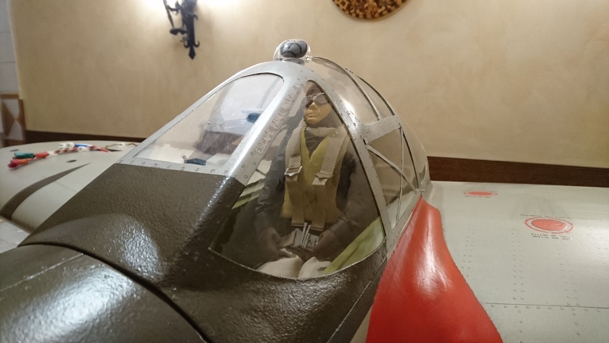
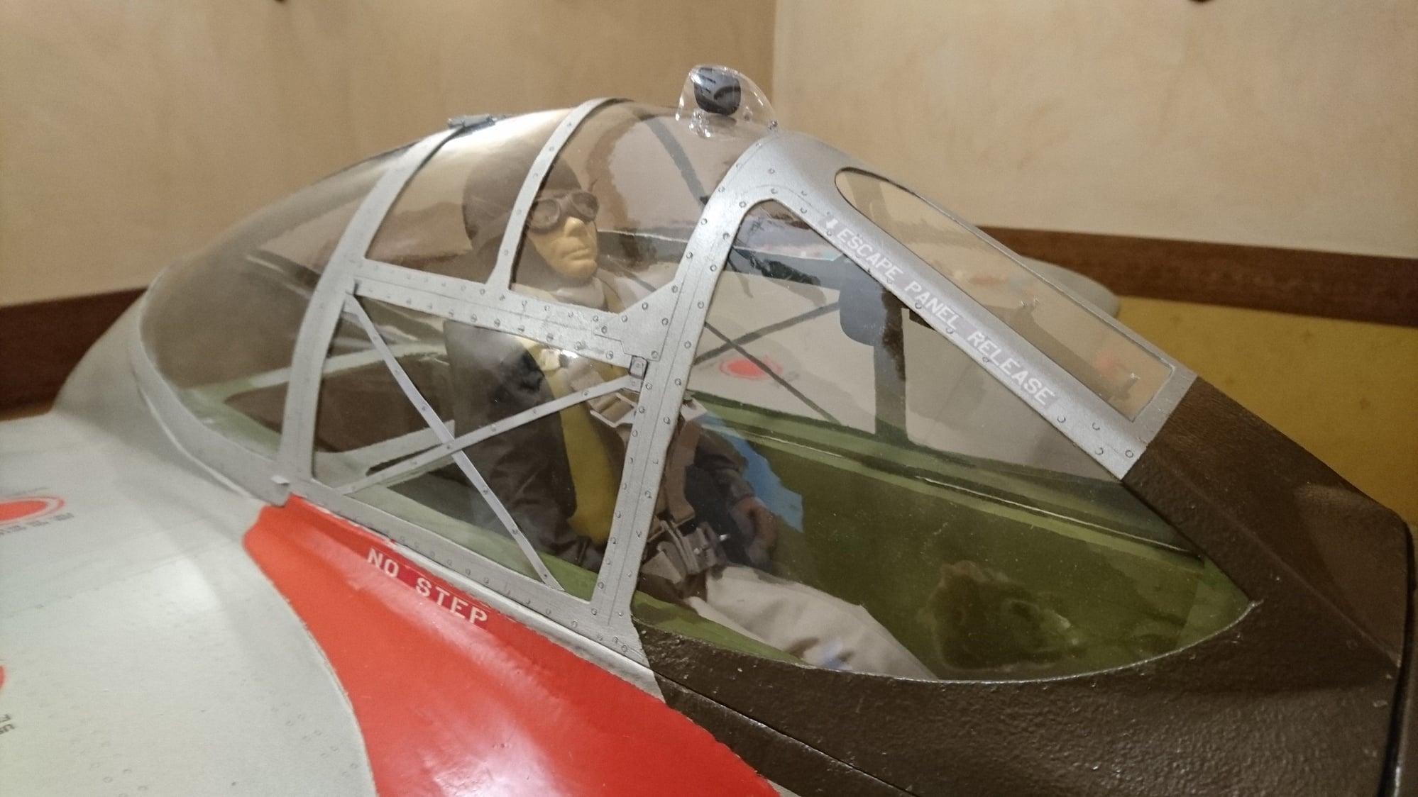
After several years in the drawer waiting for this memorable moment, I have finally been able to place Captain Paul Sabo where he deserves. I didn't want to do it until the canopy was finished.
Although, as I mentioned, I have conditioned the development of the instrumentation to the flight test, it is essential to have the pilot well seated and with a minimum of details. Thus, at least the rearview fairing, the upper canopy hinge and the gun sight collimator give an aceptable exterior appearance for the first flights. I even dared to put the machine guns.
So, next step is to rescue the engines from the drawer, retest them on the bench and mount them on the plane.
09-18-2019, 11:31 PM
#90
Thread Starter
Join Date: Oct 2012
Location: ZARAGOZA, SPAIN
Posts: 97
Likes: 0
Received 0 Likes
on
0 Posts
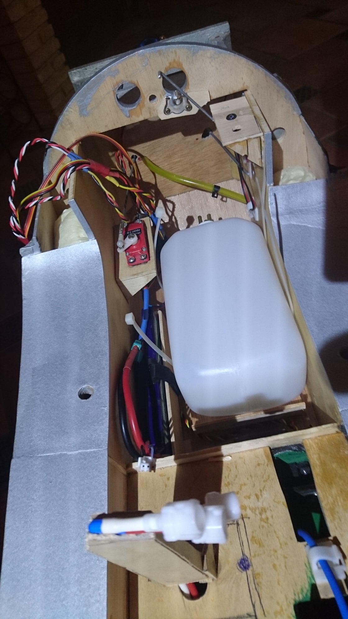
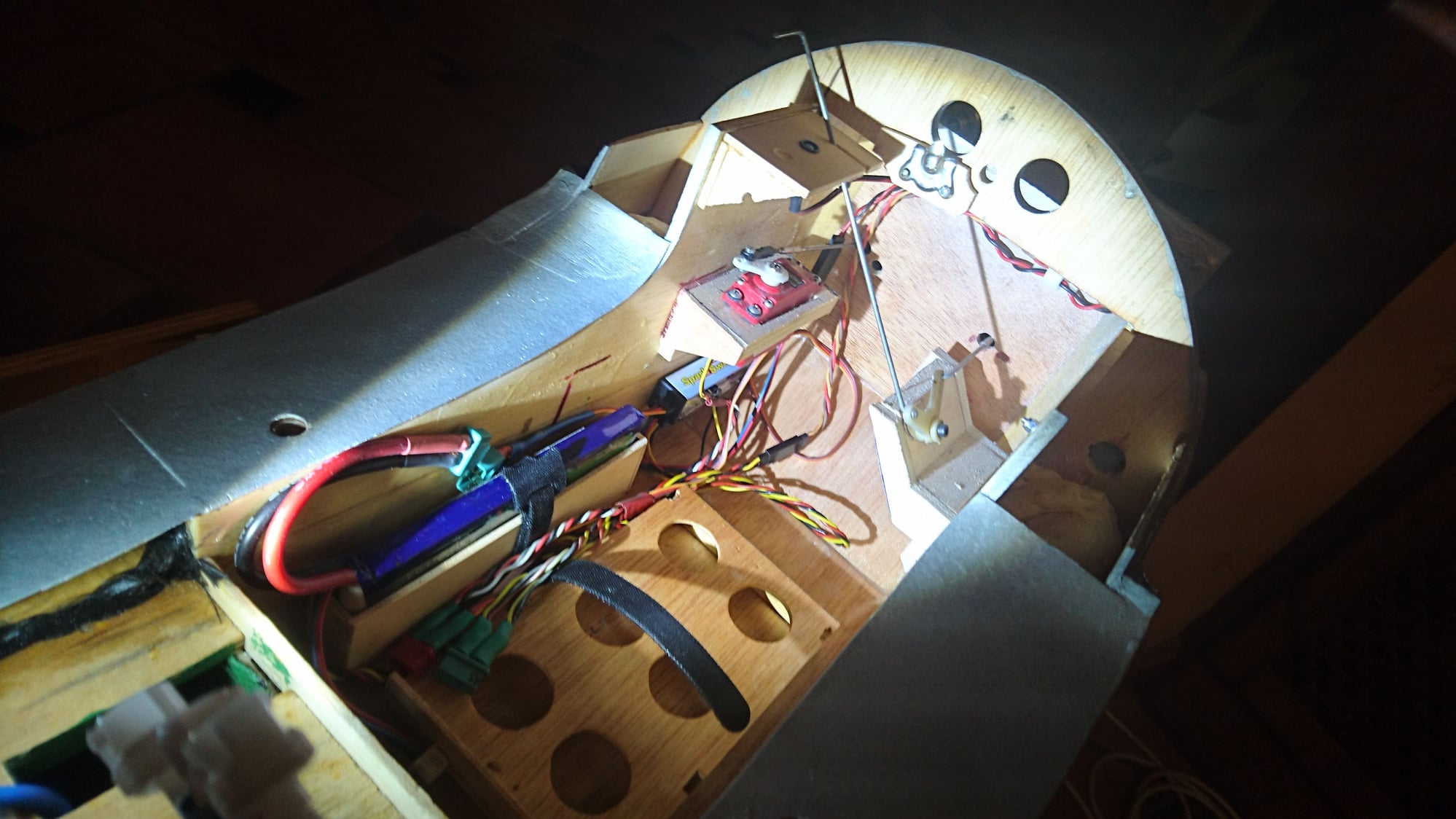
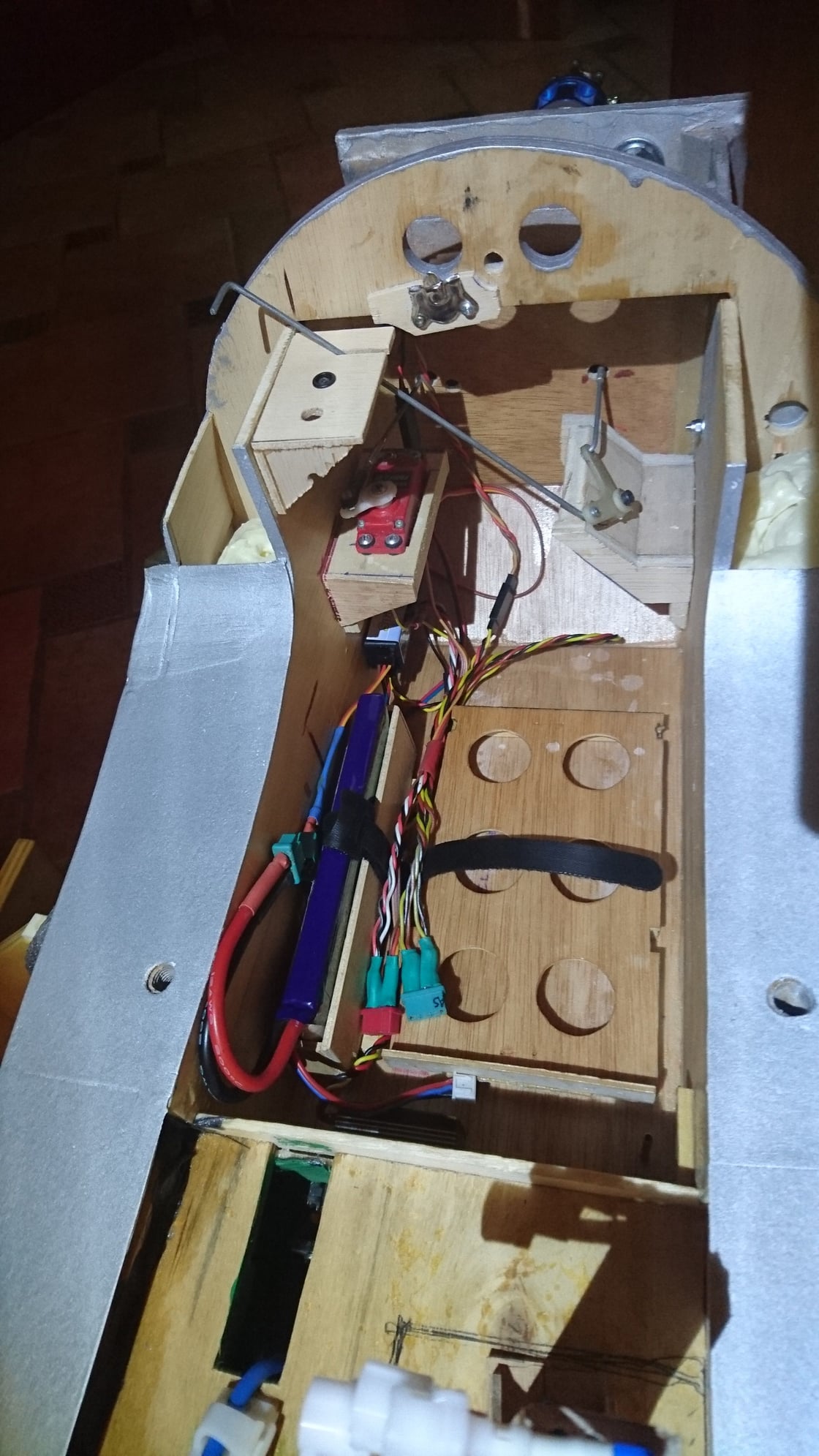
Hello everyone:
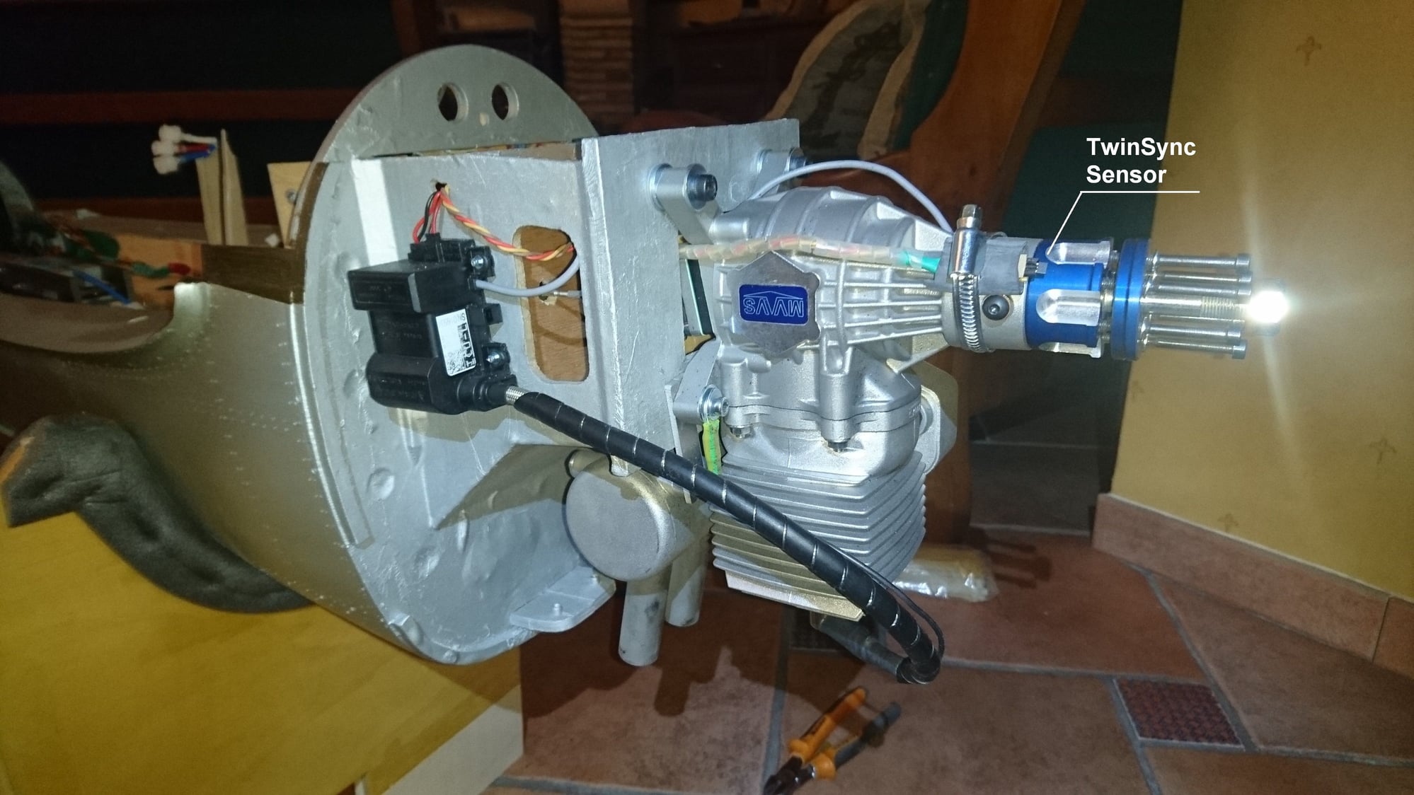
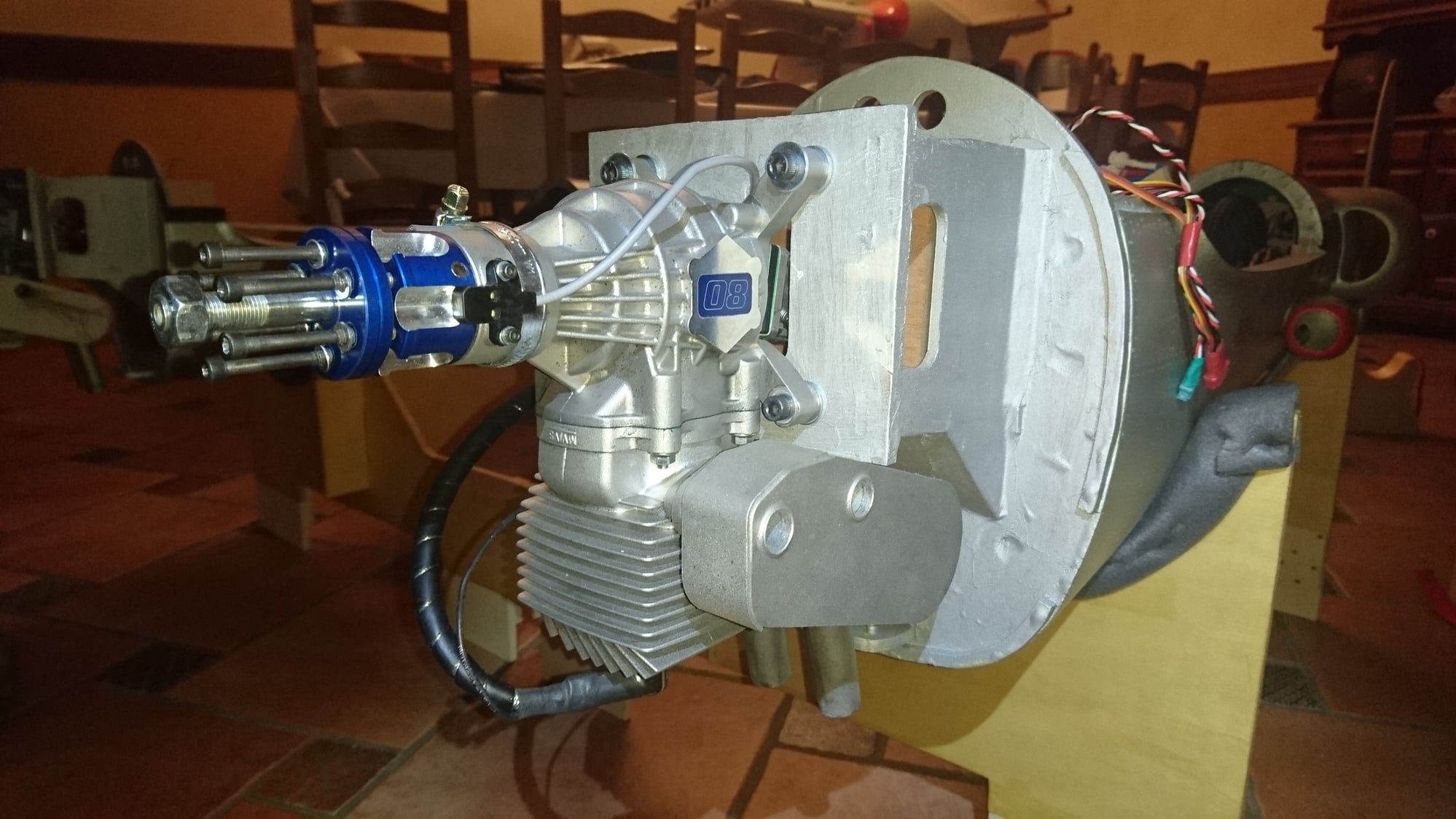
I show you a couple of pics of the engines in place. Due to the type used, there is no space problem. I have marked the engine TwinSync sensor, which is the most relevant of the installation.
I show you a couple of pics of the engines in place. Due to the type used, there is no space problem. I have marked the engine TwinSync sensor, which is the most relevant of the installation.
 09-22-2019, 05:13 AM
#92

Join Date: Sep 2007
Location: Beeton, Ontario, CANADA
Posts: 1,339
Likes: 0
Received 5 Likes
on
4 Posts
Just incredible work fbielsa. The cockpit and canopy is a major accomplishment all on its own. I can only imagine the lack of responses to this thread is because your standards are so high that they are simply left speechless.
Trevor
Trevor
09-23-2019, 02:36 AM
#93
Thread Starter
Join Date: Oct 2012
Location: ZARAGOZA, SPAIN
Posts: 97
Likes: 0
Received 0 Likes
on
0 Posts
Just incredible work fbielsa. The cockpit and canopy is a major accomplishment all on its own. I can only imagine the lack of responses to this thread is because your standards are so high that they are simply left speechless.
Trevor
Trevor
I appreciate your kind words and recognition of the work presented. My main purpose of exposing it in this forum is to spread an unusual work, due to its great constructive complication and size, with the illusion that everyone interested can benefit from its content.
Only with that I consider myself lucky.
I know that this model is not exceptional and that there are precedents of similar scale with a better finish than mine, but, as far as I know, both in Europe and in America, they are very scarce. Although, as you said, I miss a higher level of participation, I am satisfied with the opportunity to make it public in this forum.
I apologize for my English, which is something elementary, but I have tried to do my best to explain the whole process, from the difficulties for its gestation to those of the building process.
I will continue to report the final steps before maiden flight.
Kind Regards.
Fernando
09-28-2019, 10:39 AM
#94
Thread Starter
Join Date: Oct 2012
Location: ZARAGOZA, SPAIN
Posts: 97
Likes: 0
Received 0 Likes
on
0 Posts
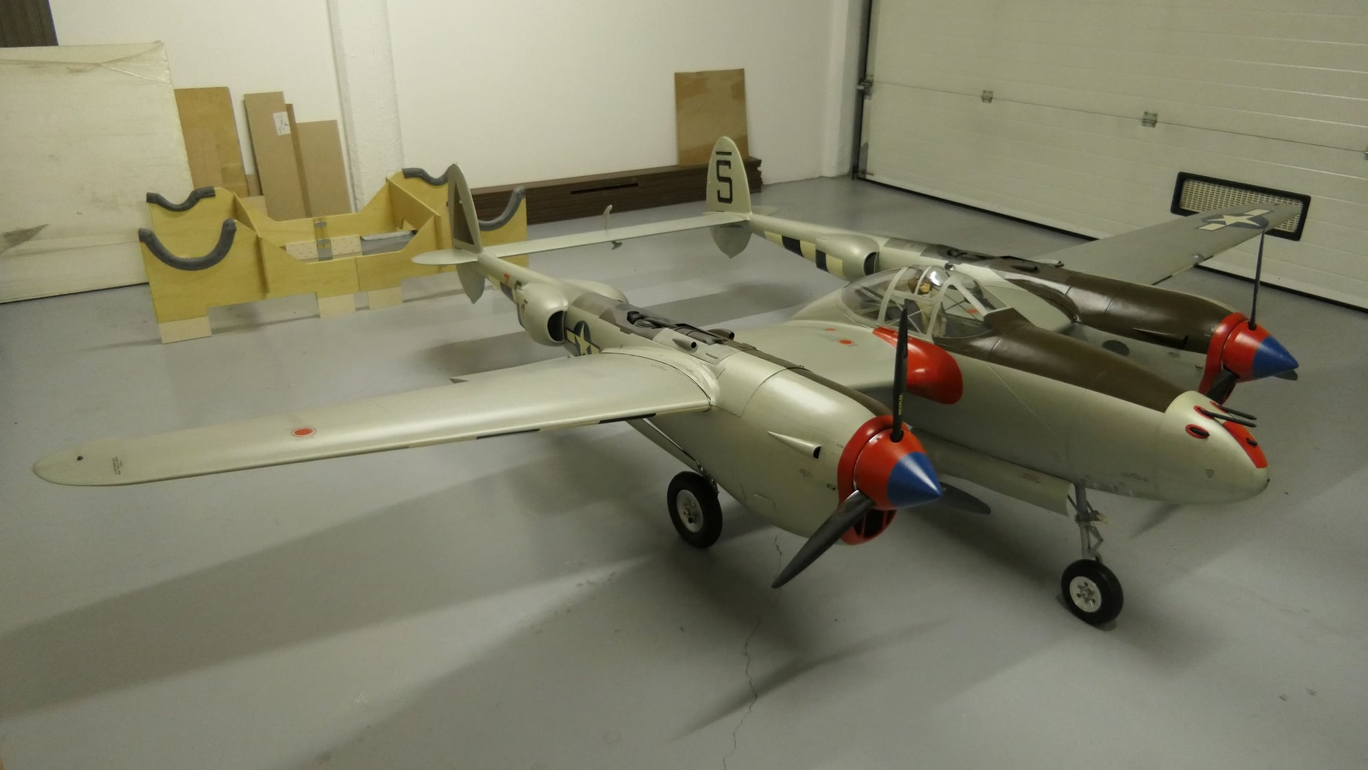
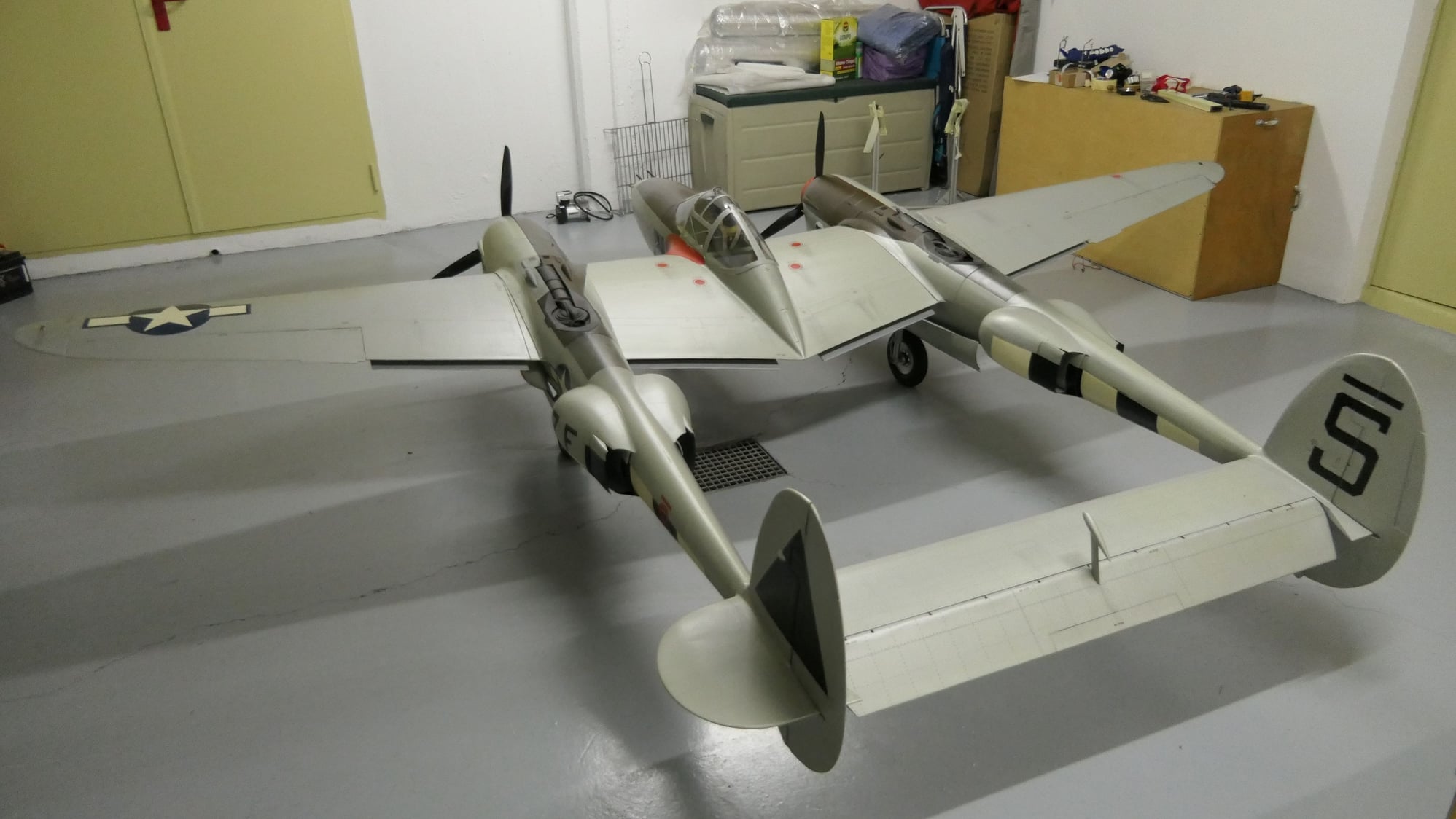
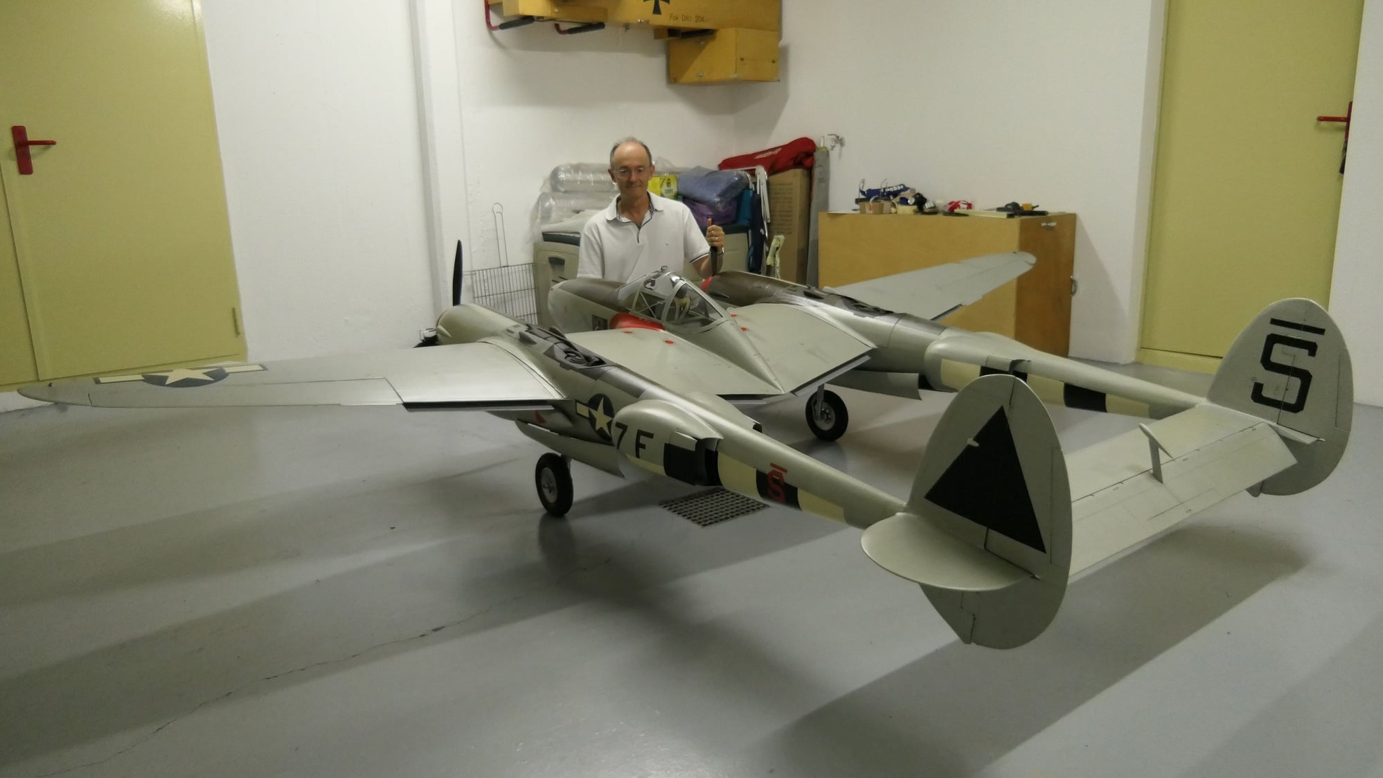
Hello everyone:
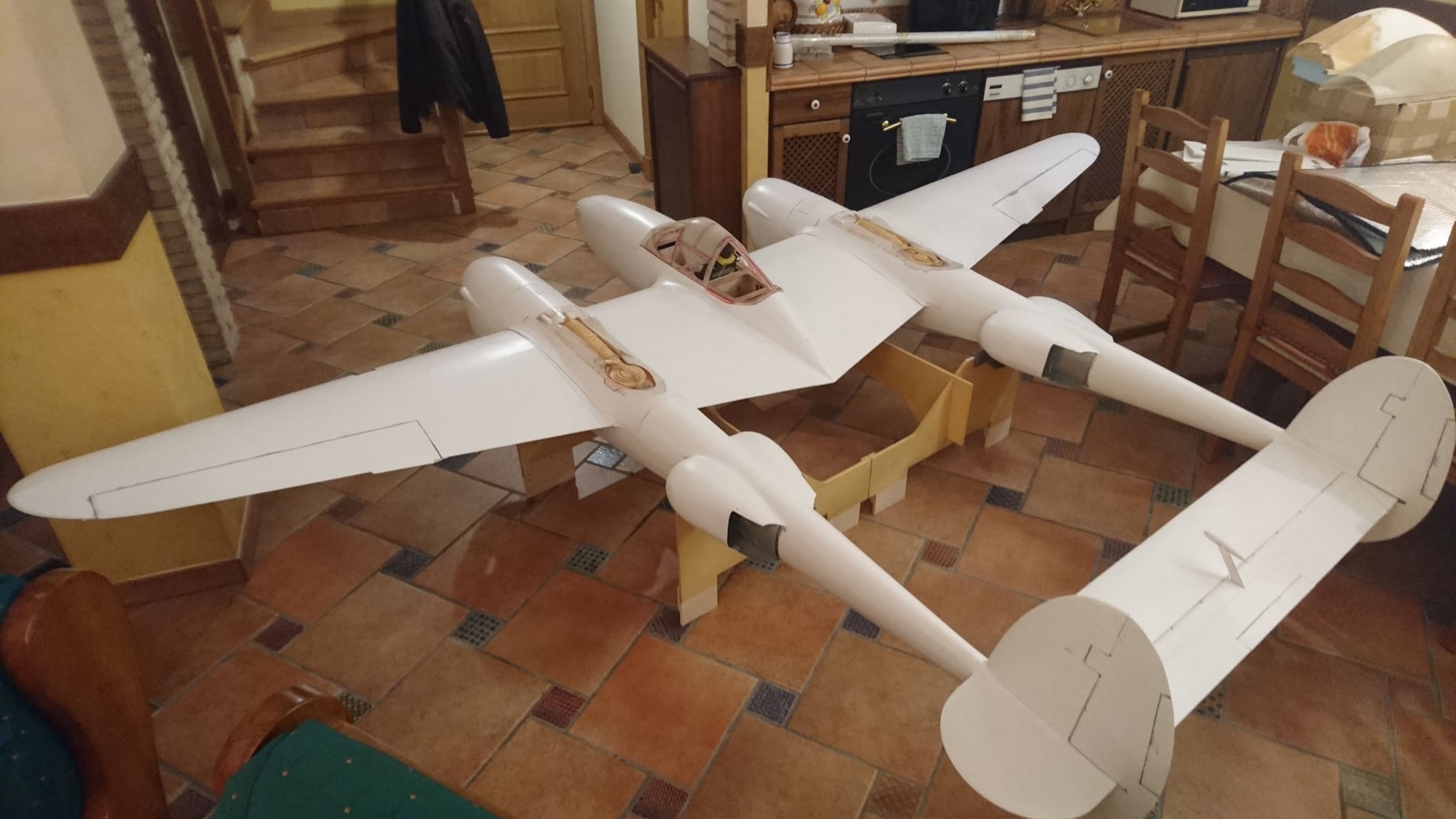
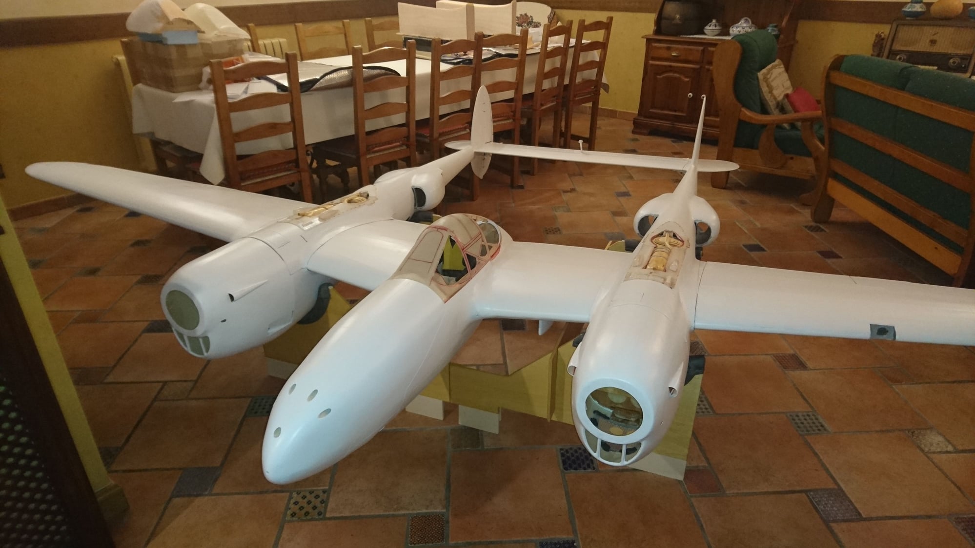
Here is the P-38 resting on the ground for the first time on its wheels, since until now she had not left the mounting bench.
I have taken the opportunity to perform the first counterweight tests according to the calculated CG.
I still have to do some more checking, so I can tell you the final weight of the model soon.
 10-02-2019, 02:22 AM
#96
Thread Starter
Join Date: Oct 2012
Location: ZARAGOZA, SPAIN
Posts: 97
Likes: 0
Received 0 Likes
on
0 Posts
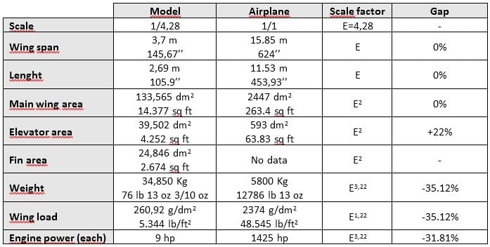
Balance and final dimensions
The center of gravity is placed to 22,6 cm (8.9’’) from the leading edge of the central wing, at the geometric union with the nacelle (bypassing the “karman”), with the landing gear up, pneumatic circuit at 3,5 bar (50 psi) and empty fuel tank.
With the location of the equipment mentioned, it has only been necessary to ballast the nose with 450 g (15,87 oz), taking advantage of the hole provided at the end of the nacelle frame, which has resulted in a final weight of 34.85 kg (76 lb 13 oz).
This has fulfilled all my expectations, since the previous calculations were based on a maximum expected weight of 35 kilograms. If you remember, in my post #8, I already told you that I chose the power of the engines according to an estimated wing load, when the plane was little more than glued sticks, which has not differed at all from that finally obtained. Blessed chance or clinical eye? I don't know, but I'm glad it was like that.
I suppose that it may seem an excessive weight to some of you, but given the scale and type of aircraft, it has been 35% lower than expected (remember Rousselot's formulas), so it is expected that the plane has a flight very realistic for its weight / power reason.
I show you, in tabular form, a relation of the main final dimensions of the model and its difference from the expected.
 10-08-2019, 05:54 AM
#99
Thread Starter
Join Date: Oct 2012
Location: ZARAGOZA, SPAIN
Posts: 97
Likes: 0
Received 0 Likes
on
0 Posts
Mixes and control suface throws
I have planned a slight mix in elevator to descend (1/32’’) when the flaps are full down; In the same way, mixed slightly to ascend when the landing gear is put down (3/64’’), since its turning radius and weight are great enough. Once the elevator gain is set on the i-Gyro SRS®, these mixes should be canceled if the Heading mode is turned on at this axis, but it is advisable to have them active in the first landings without gyro.
I have set the following control surface throws to start from: +13ş/-7.5ş in ailerons, ± 16ş in elevator, ± 20ş in rudder and the -34ş of deflection allowed by the type of Fowler hinges used in flap. I hope it will be enough.
10-27-2019, 09:58 AM
#100
Thread Starter
Join Date: Oct 2012
Location: ZARAGOZA, SPAIN
Posts: 97
Likes: 0
Received 0 Likes
on
0 Posts
Hello everybody:
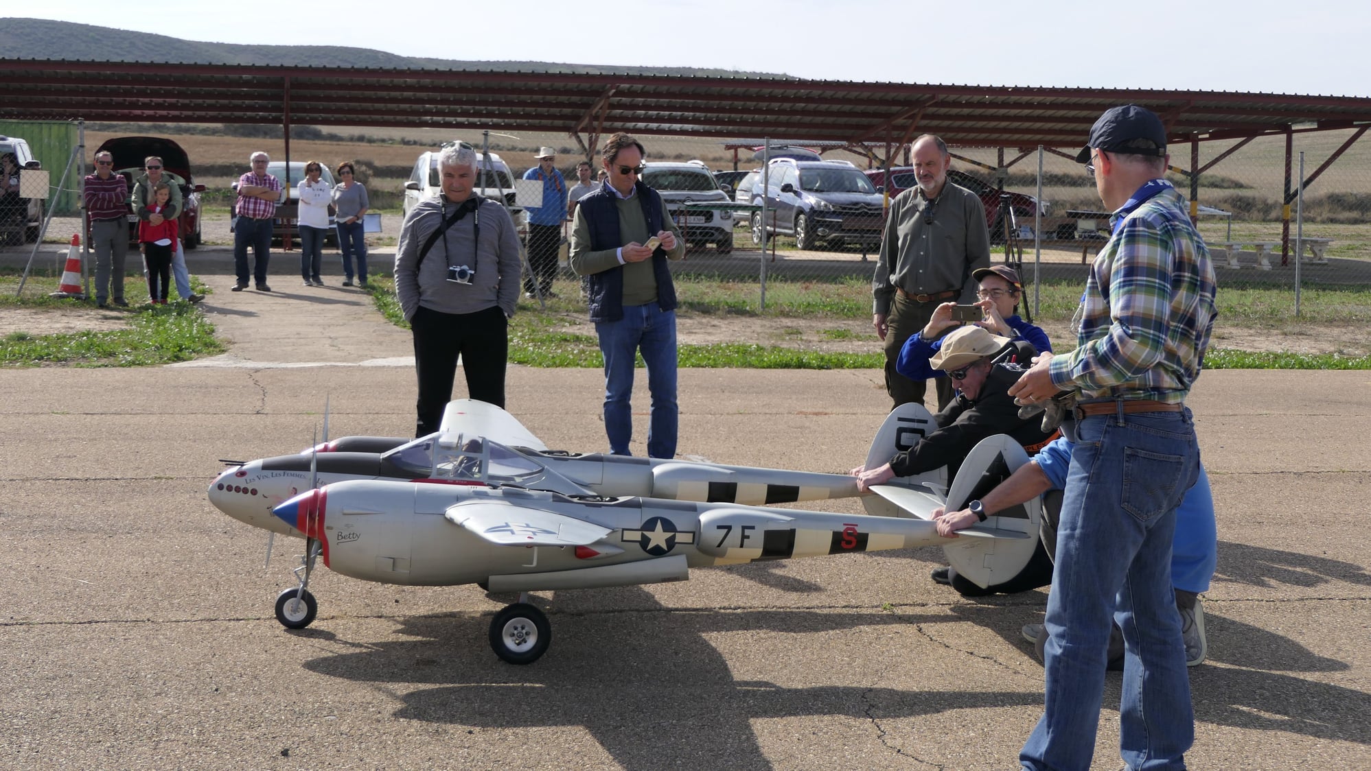
It seemed that he was not going to arrive, but D-Day he has been presented inexorably.
After being able to coordinate all the logistics and necessary human help, today the plane has met the airfield, taking advantage of a delicious weather this morning.
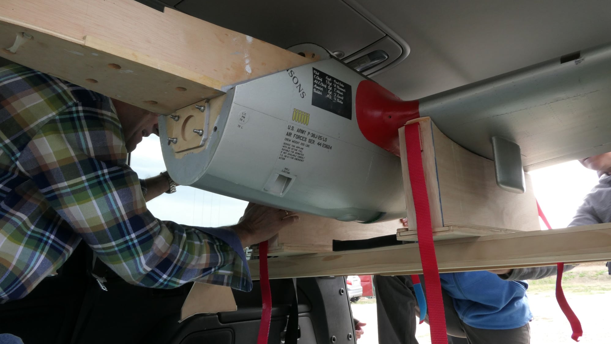
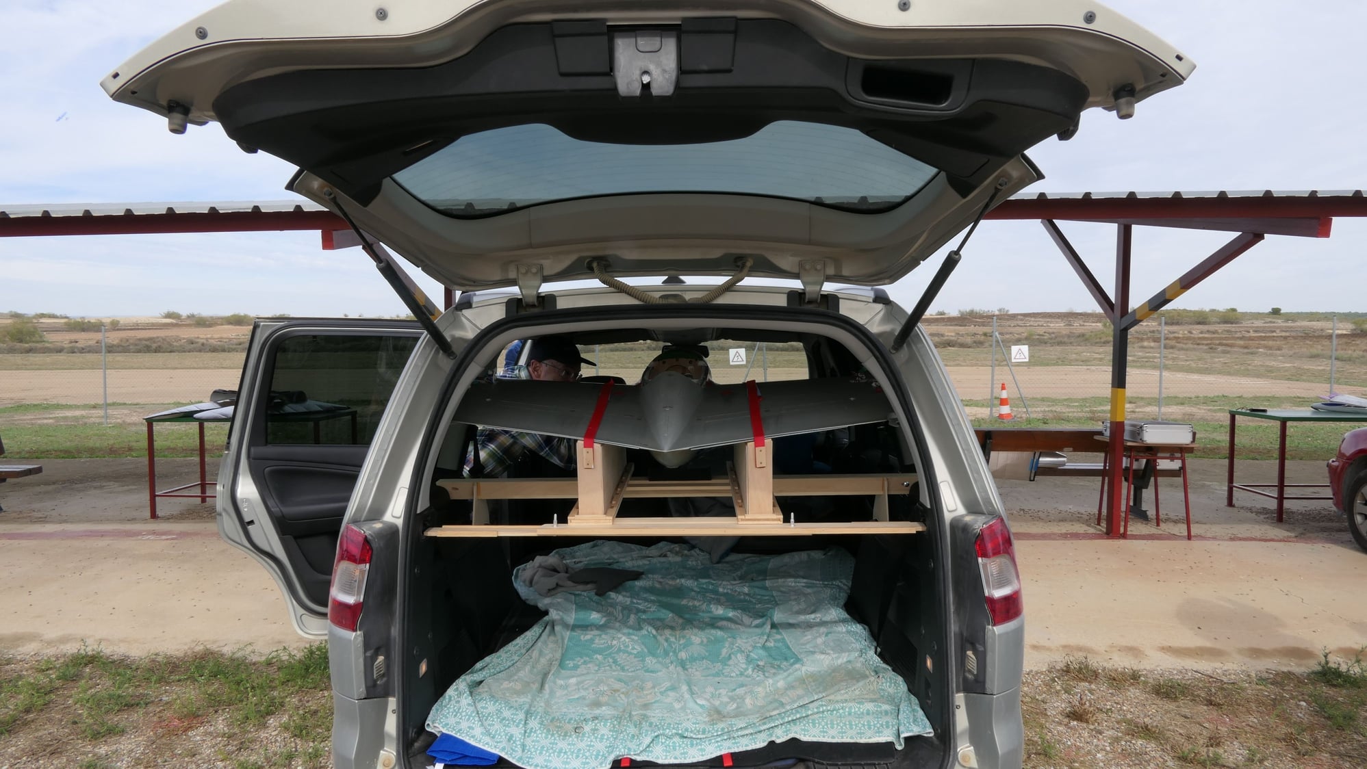
In my case, the transportation of everything necessary has not been easy, due to the complex support and anchoring system that I had to enable in my vehicle due to the size of the central part and the fuselages.
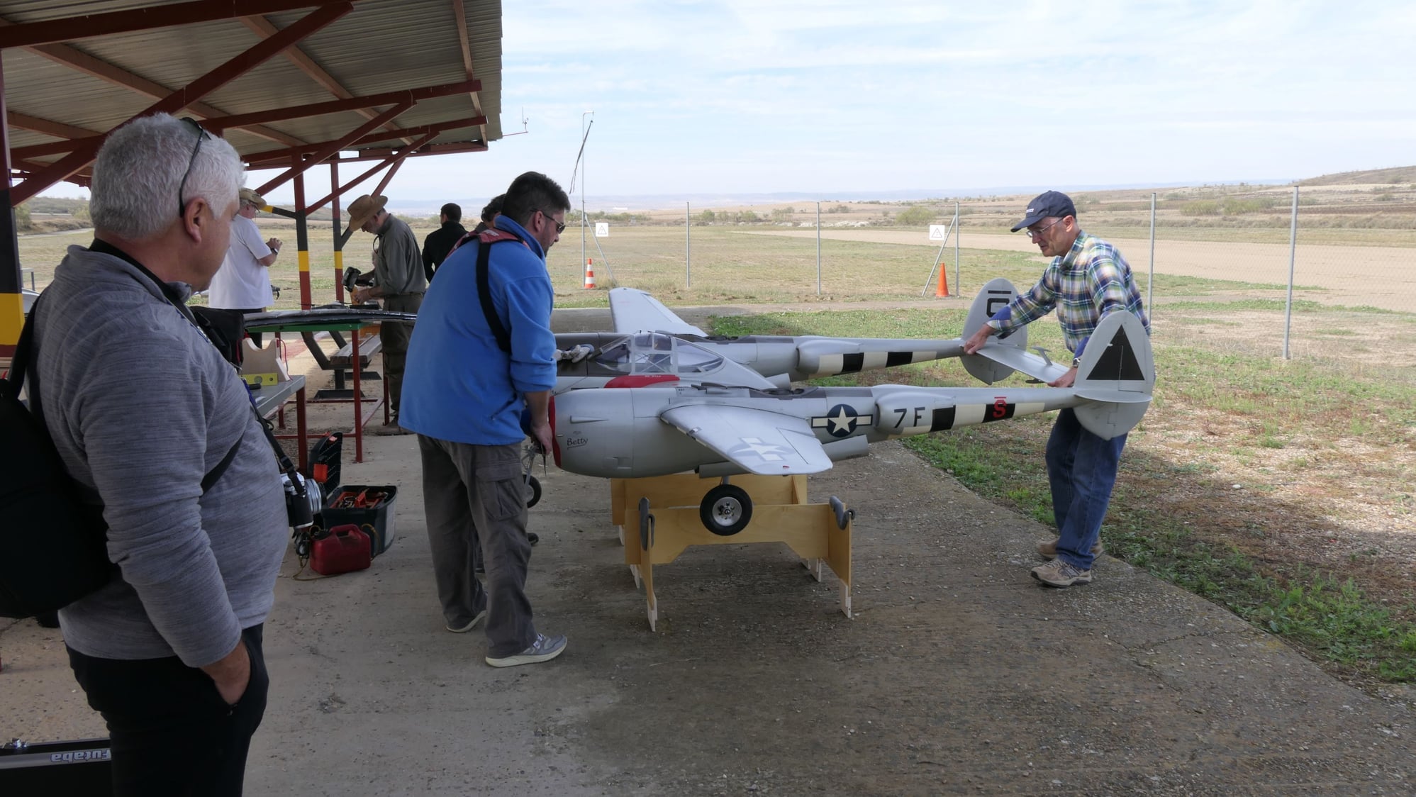
Less complicated is the model assembly, which is facilitated by the bench used in construction and a bubble level that helps position both fuselages to receive the central wing. With practice it does not take more than fifteen minutes.
Of course, once mounted the model, leaves no one indifferent. Its elegance of lines and big size overwhelm those present, causing all kinds of comments that increase, even more if possible, the anxiety inherent in the fact of putting so many years of work and sleepless nights on the air. With the collaboration of at least two assistants, I proceed to lift the plane from the assembly bench and place it on the runway for the mandatory range test. Actually, its almost 35 kg are noticeable, so we must lift the model for each engine shaft and tail.
Once on the ground, this test is carried out with both engines running and stopped, there is hardly any difference between the two situations.
Is time to review the configuration of the i-Gyro, still in idle state, and set the TwinSync, which requires the operation of the two engines.
At last, we observed a difference in idle behavior of the right engine, which tended to stop when the engine was cut. Change of regulation when enclosing the engine in the cowl. As time was on us, we decided to make the corresponding adjustments another day, and return another day to try.
I will be post some static photo later.
It seemed that he was not going to arrive, but D-Day he has been presented inexorably.
After being able to coordinate all the logistics and necessary human help, today the plane has met the airfield, taking advantage of a delicious weather this morning.
In my case, the transportation of everything necessary has not been easy, due to the complex support and anchoring system that I had to enable in my vehicle due to the size of the central part and the fuselages.
Less complicated is the model assembly, which is facilitated by the bench used in construction and a bubble level that helps position both fuselages to receive the central wing. With practice it does not take more than fifteen minutes.
Of course, once mounted the model, leaves no one indifferent. Its elegance of lines and big size overwhelm those present, causing all kinds of comments that increase, even more if possible, the anxiety inherent in the fact of putting so many years of work and sleepless nights on the air. With the collaboration of at least two assistants, I proceed to lift the plane from the assembly bench and place it on the runway for the mandatory range test. Actually, its almost 35 kg are noticeable, so we must lift the model for each engine shaft and tail.
Once on the ground, this test is carried out with both engines running and stopped, there is hardly any difference between the two situations.
Is time to review the configuration of the i-Gyro, still in idle state, and set the TwinSync, which requires the operation of the two engines.
At last, we observed a difference in idle behavior of the right engine, which tended to stop when the engine was cut. Change of regulation when enclosing the engine in the cowl. As time was on us, we decided to make the corresponding adjustments another day, and return another day to try.
I will be post some static photo later.