


Another Full flying pivot location thread
 03-13-2015 | 01:50 PM
#1
Thread Starter

My Feedback: (15)
Joined: Jun 2002
Posts: 369
Likes: 0
Received 0 Likes
on
0 Posts
From: TX
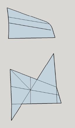
I have started a new project and am calculating the flying stab MAC and stab pivot position. My problem is that the examples show the MAC calculated on a wing that has square edges and straight lines. My wing has a round outer leading edge and the root/ tip are not parallel. If I fudged the shape to make the example work for my wing, I will be adding or subtracting area which would change the true MAC. Another concern is do I extend the root and tip lines in the direction they are currently going since they are not parallel to each other? What about the curved root? I included a drawing of the actual stab (on top) with a MAC line and a 25% MAC line as well as a rendering of a "fudged" one with the MAC reference lines. Thanks for entertaining another flying stab question.


 03-13-2015 | 09:57 PM
#3


If your sketch is of the shape you're building then the curve and angle at the tip isn't going to be enough to matter. And if you use the MAC indicated by the diagram you posted the slight bit of area of the raked tip will simply mean that if you put the pivot right on the 25% of the MAC shown by the diagram that the little bit of tip area will mean that it's more like 24 or 23.5% instead of spot on 25%. And that's fine too. It'll just provide a light self centering force.
03-14-2015 | 03:36 PM
#4
Thread Starter
My Feedback: (15)
Joined: Jun 2002
Posts: 369
Likes: 0
Received 0 Likes
on
0 Posts
From: TX
Awesome guys, so the front line on the top drawing which is the actual shape is 25% MAC, it looks a little further forward than my jets, how does it look to y'all? I am sure I will chime in with some other stuff later. Thanks.
03-17-2015 | 09:55 AM
#7
In the sketch below I've added in some red stuff to indicate a couple of options. On the upper sketch I've shown a red line which is eyeball accurrized to sit on the quarter chord line of the root and tip chords. If you can live with a swept hinge line this would give you the balanced low effort servo load. But the swept nature of the hinge line means that the root face is going to arc through some odd gyrations with the trailing edge corner arcing outward from the fuselage and the leading edge point arcing inwards due to the pivot sweep angle.
The lower part shows the hinge line for a straight across pivot that won't arc outwards or inwards. It uses the MAC chord length and location given by the graphic MAC solution you already sketched. That chord line at the intersection of the mid line and angled line is your MAC. And again I eyeballed the red line to show where the 25% location for the pivot axis would be located.
03-17-2015 | 12:25 PM
#9
Thread Starter
My Feedback: (15)
Joined: Jun 2002
Posts: 369
Likes: 0
Received 0 Likes
on
0 Posts
From: TX
Ok so now I have even more questions. So you are saying that there are options for the hinge line, but everywhere I've read about stab pivot location pretty much states 20-30% of MAC. If choosing the swept hinge line, would the stab pivot need to enter the fuse at the hinge line angle to make it work? There is a pretty big difference it appears between the locations of the two so my question is do they use different mechanics (ie angles) to allow them to work with such different locations along the MAC line? I am accustomed to the pivot being perpendicular to the root as well as this being the scale configuration. I just want to learn as much as I can about this as well as make sure I get my pivot in the correct location. So if I am understanding correctly, I should put the pivot point line 90 degrees to the MAC line, not parallel to the leading edge as I have it in the top picture (which is why it looked wrong to me). So the red line in the bottom picture is your eyeballed location of the stab pivot with a conventional hinge line? I will draw this in CAD for accuracy as well as send it to Dan for more visualization and confirmation. I wasn't going to disclose this but maybe it will help shed some light on the subject. This is an A6 stab. I was told by a "very knowledgably" person to put it in the full scale position but I don't have a full scale A6 to measure.
03-28-2015 | 10:59 AM
#10
It doesn't matter how you set the pivot line as long as you have 25% of the area ahead of the pivot and 75% behind. If you pivot along the 25% chord line, which is a swept line, then your pivot axis joiner rod obviously needs to enter into the fuselage at the same angle. In this case because you'd be using the 25% CHORD LINE that runs along the span the MAC calculation isn't needed and doesn't mean anything. You're working with a whole other method for setting the pivot to get the 1:3 area ratio which doesn't need the MAC location for this. Having said this since it's a simple swept shape the 25% chord line will pass through the 25% MAC line as well. It has to since the MAC is just one more point along the span.
The reason why the straight across line enters the fuselage so much farther back is due to the sweep angle of the surface shape moving the MAC location back so far. There's still 25% of the total surface area ahead of the pivot axis with this method. Just the pivot axis changes because the pivoting is occurring along a different direction.
I would not have even mentioned the idea of a swept hinge line other than because your first part of the sketch showed a line running at what looked mistakenly like a spanwise 25% chord line. I was just correcting the line to show what the proper 25% chord line should look like in case you were considering using a swept hinge line.
And you're right that the straight across pivot method is far more common. And since you've now added that this is a scale model clearly it's the way you should proceed.
Sorry if my added line on the first part caused you any loss of sleep....


