


BJ Craft Muscle Cloud Build

The following 2 users liked this post by J-P:
doblerizo (01-04-2025),
ReverseLogic (05-22-2025)
 01-22-2025 | 04:15 PM
#2
Thread Starter

My Feedback: (1)

I was feeling ready for the season 2025 with two LEADER G, one powered by a TMCR, the second one brand new by an ADVERRUN V2, and had no new project in mind.
All started after spending a few days in LA with my friend Steve HANNAH when I saw how was performing his new ULTIMATE BISIDE I was following the thread.
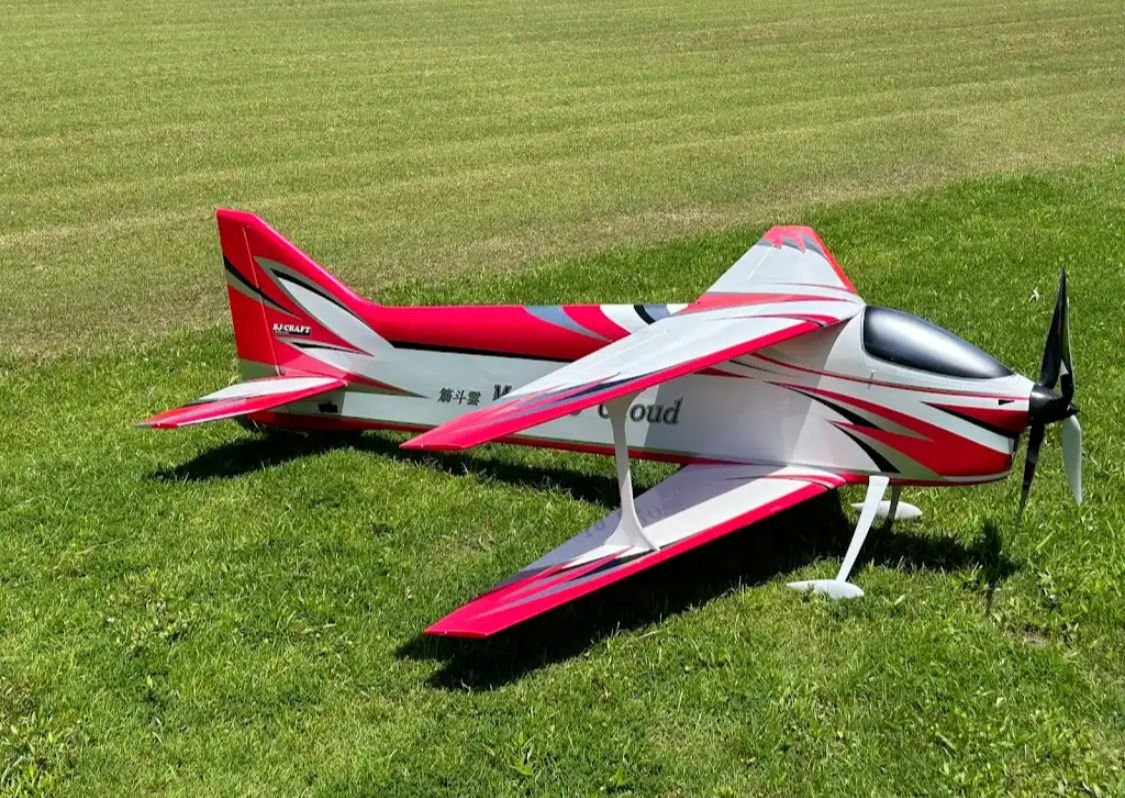
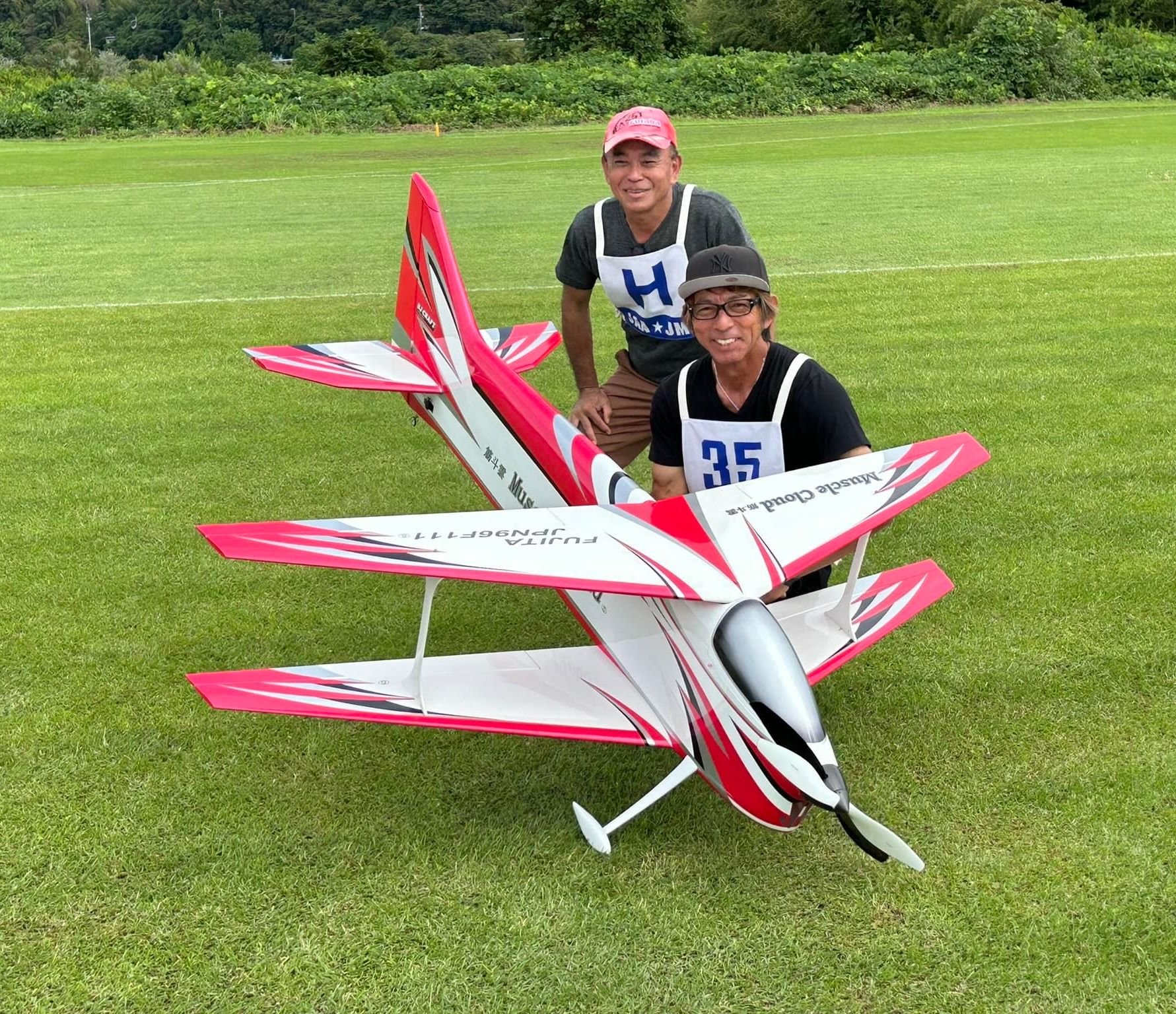
Incidentally I received a few pictures of a new model, the MUSCLE CLOUD designed by Byung Joon PARK in cooperation with Shoichi Fujita and his Japanese Team.
The wings and stabs are the same as the ULTIMATE BISIDE, and the fuselage looks to me an enlarged LEADER fuselage.
I couldn't resist .....and contacted BJ
All started after spending a few days in LA with my friend Steve HANNAH when I saw how was performing his new ULTIMATE BISIDE I was following the thread.
Incidentally I received a few pictures of a new model, the MUSCLE CLOUD designed by Byung Joon PARK in cooperation with Shoichi Fujita and his Japanese Team.
The wings and stabs are the same as the ULTIMATE BISIDE, and the fuselage looks to me an enlarged LEADER fuselage.
I couldn't resist .....and contacted BJ
Last edited by J-P; 01-22-2025 at 04:20 PM.
01-30-2025 | 07:54 AM
#3
Thread Starter
My Feedback: (1)

This time the crate arrived without any damaged. Thanks UPS
After the IMMORTAL, the SP PASSION, the EPILOGUE and 2 LEADER G , all from BJCRAFT here is the MUSCLE CLOUD build
These are the links to two threads posted on RCU
Bj craft immortal
New bjcraft epilogue
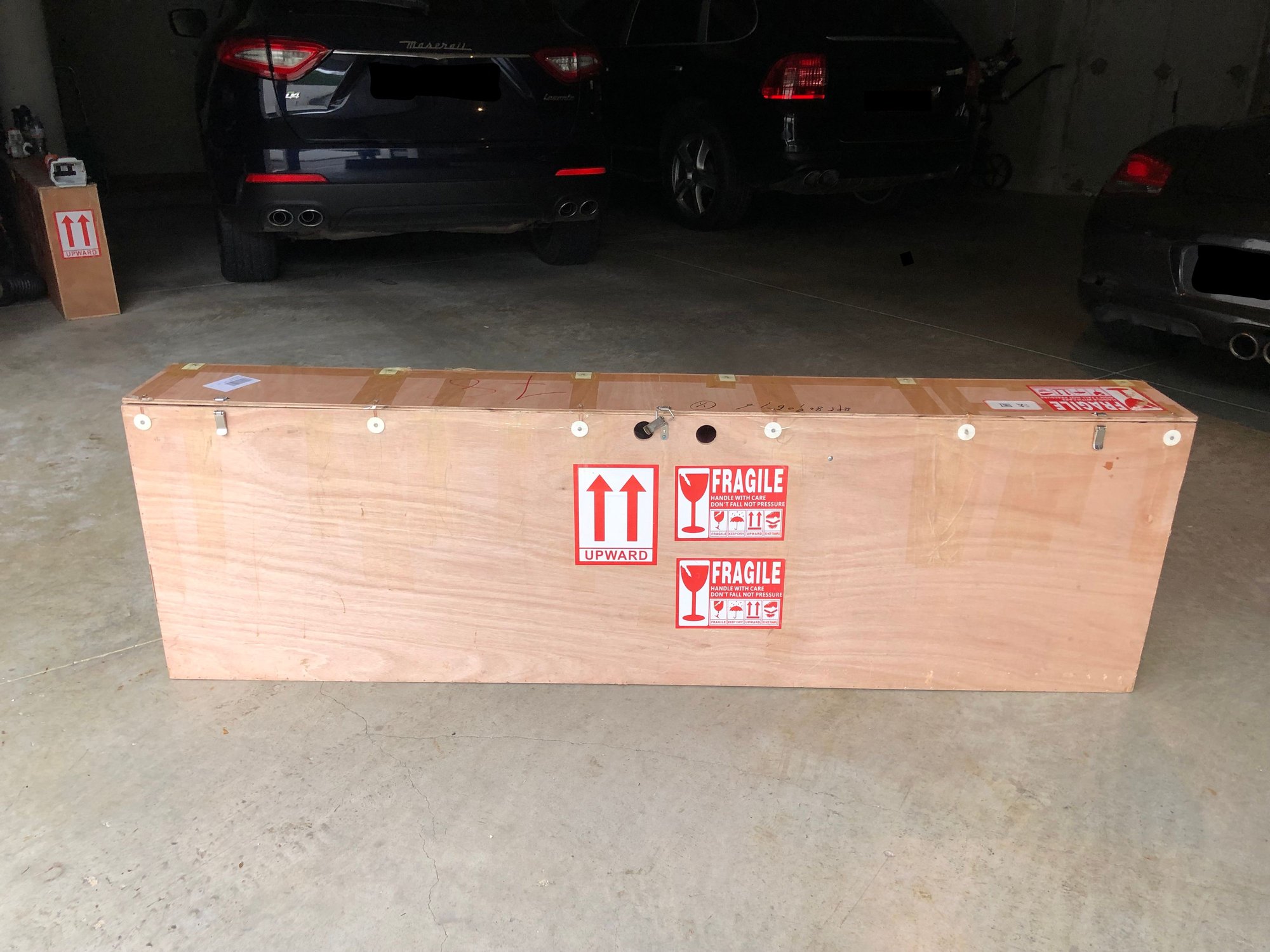
The BJ packaging is perfect, and since the crate has been reinforced, there was not a single damage on the kits I received.
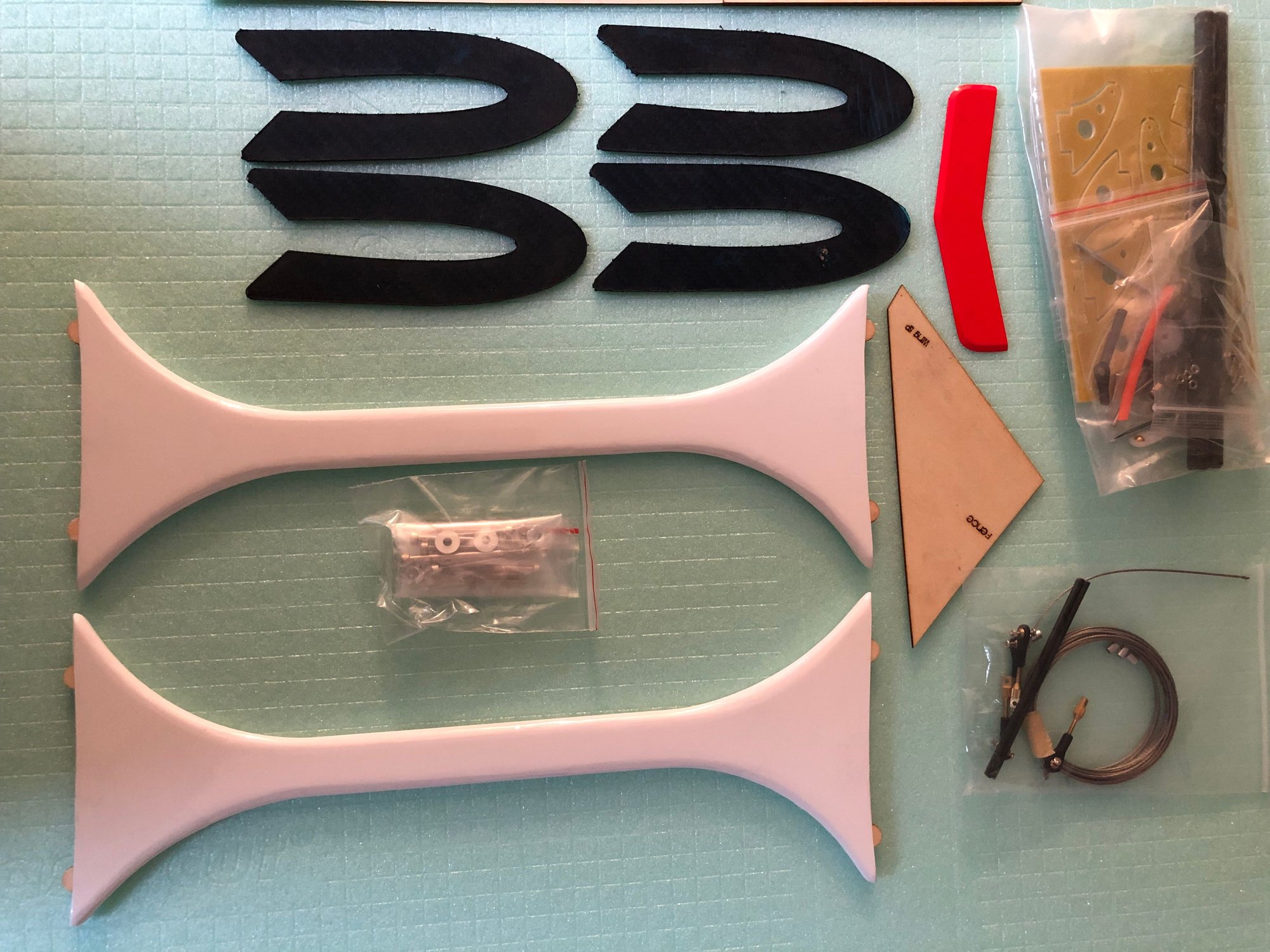
Let's see what we have in this plywood box
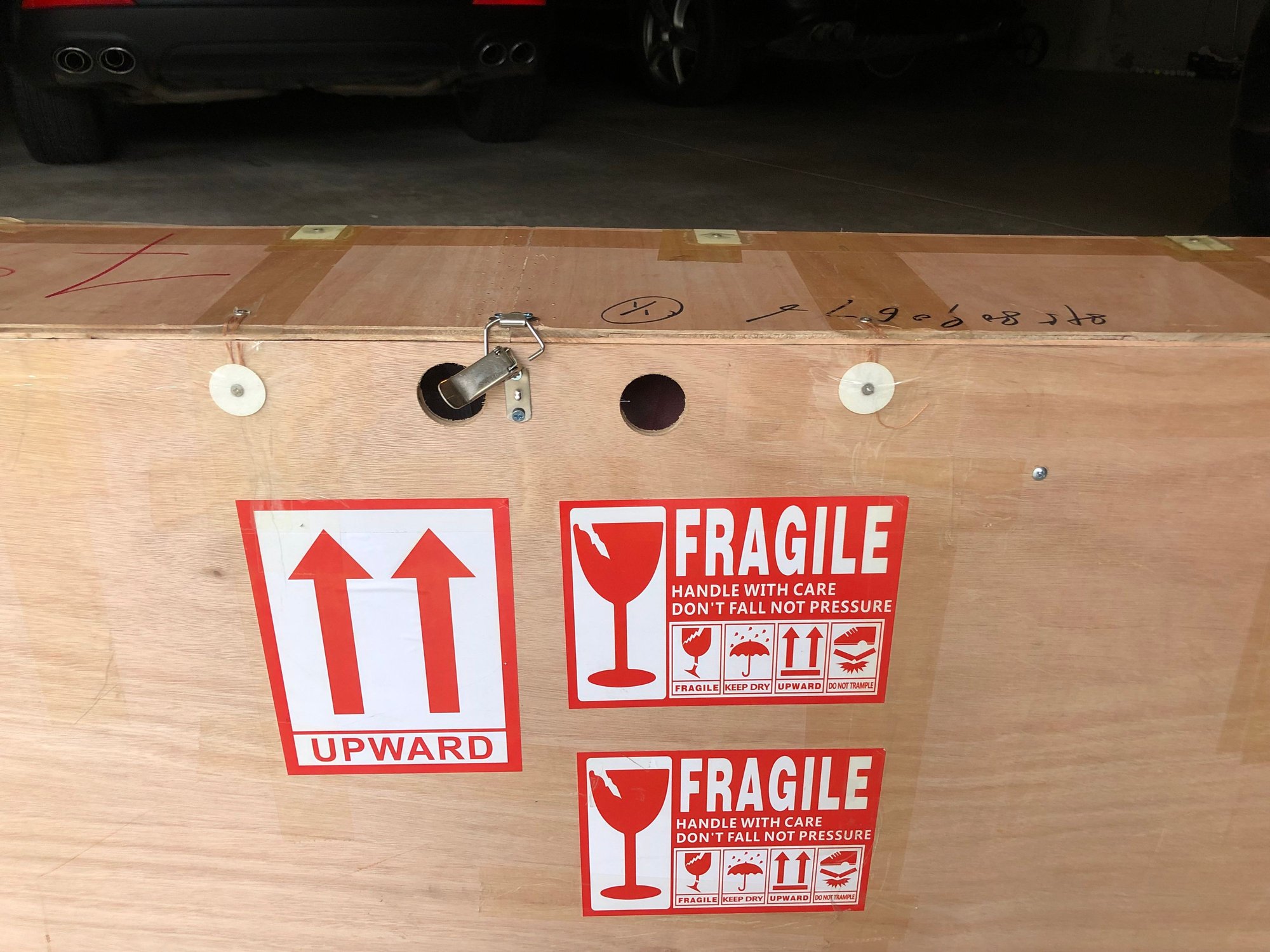
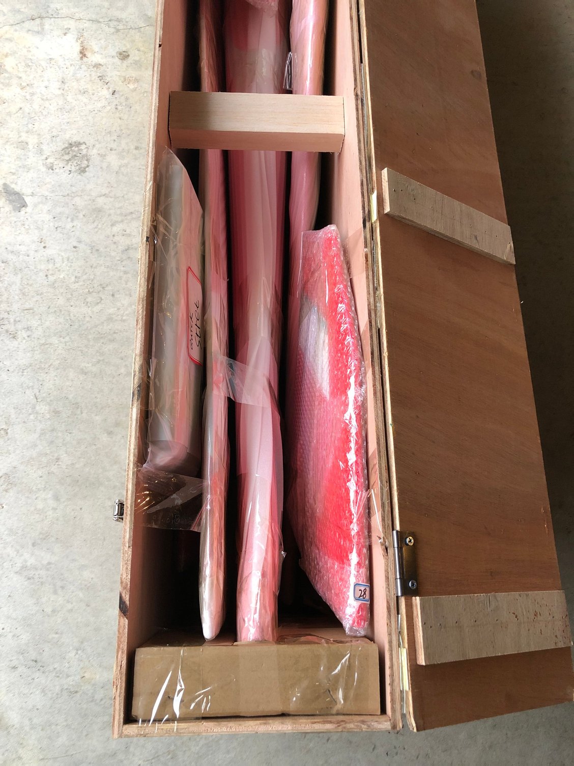
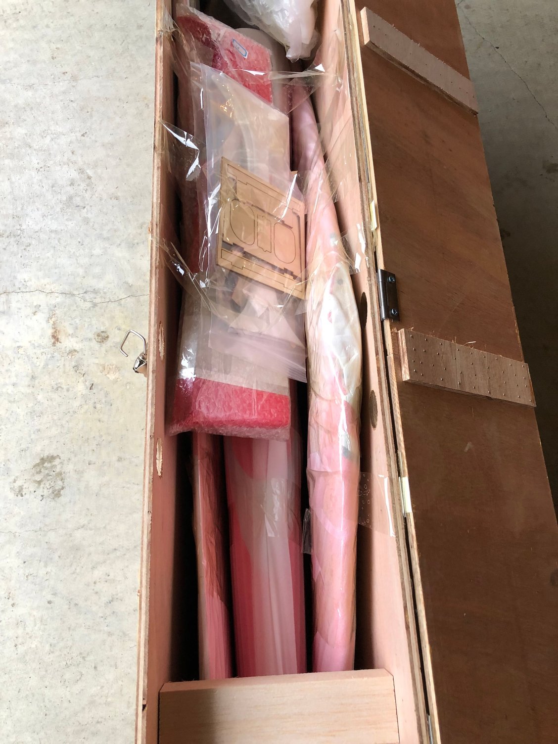
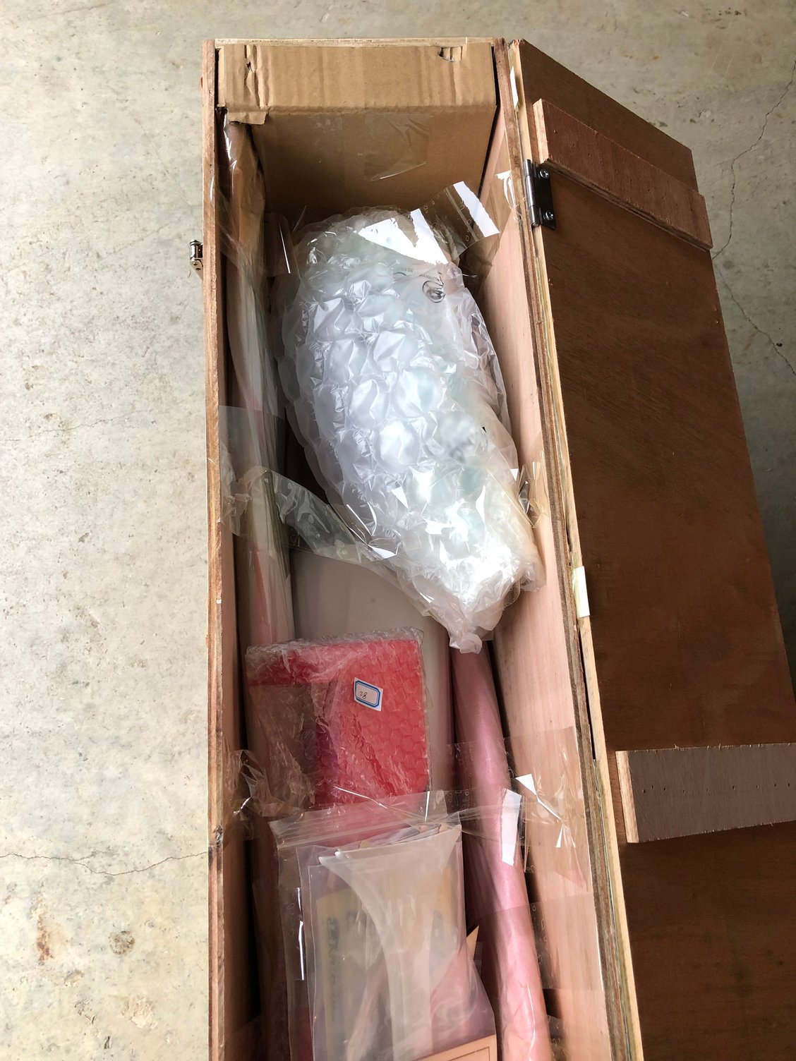
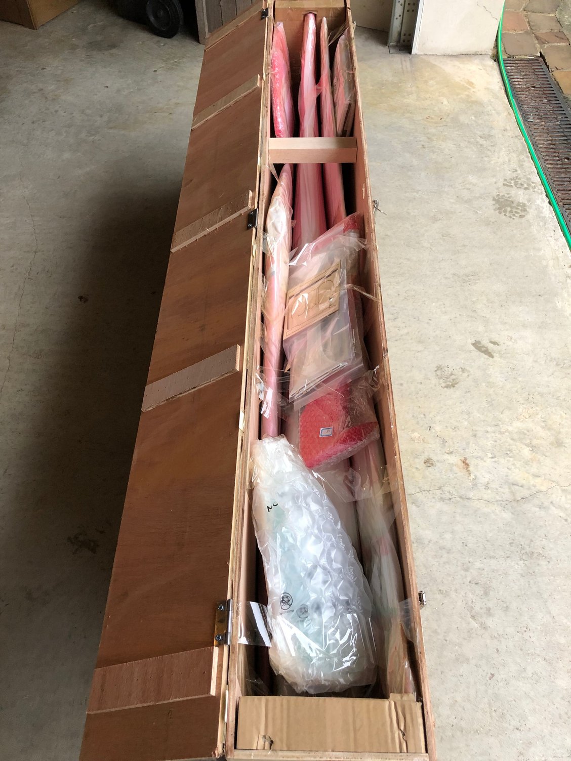
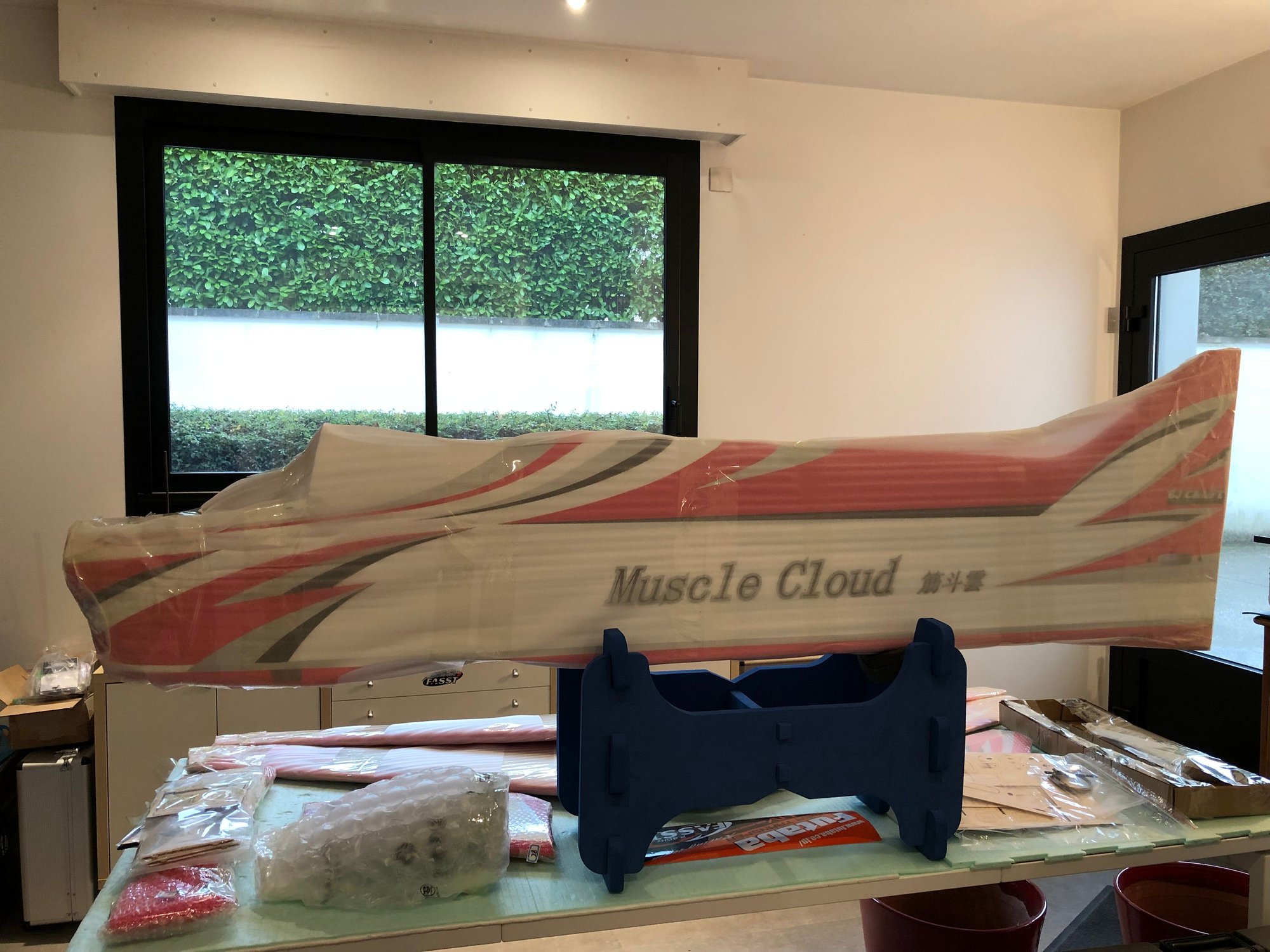
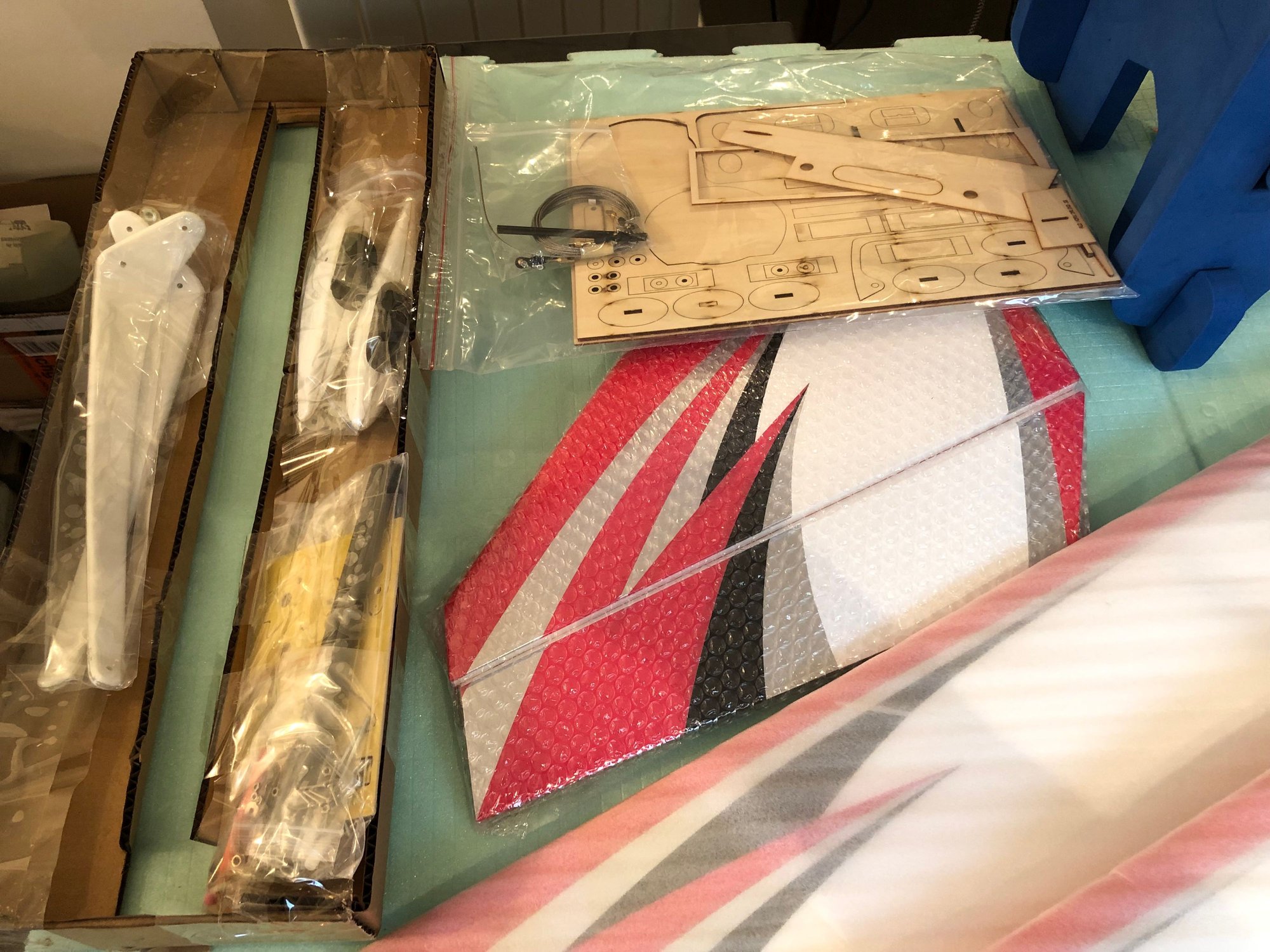
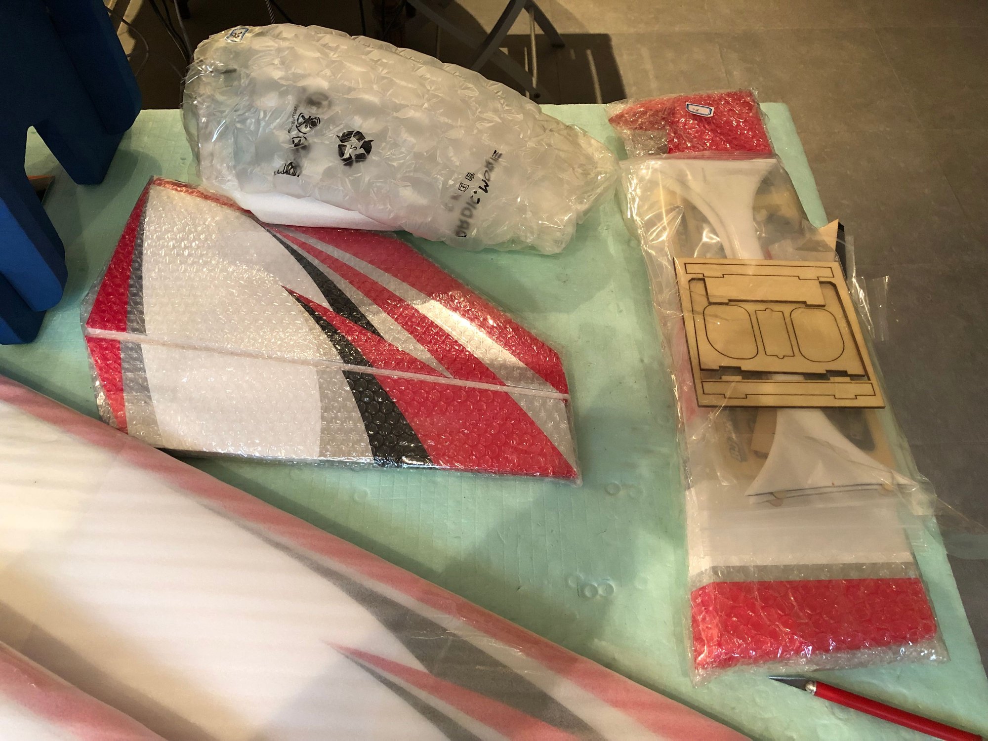
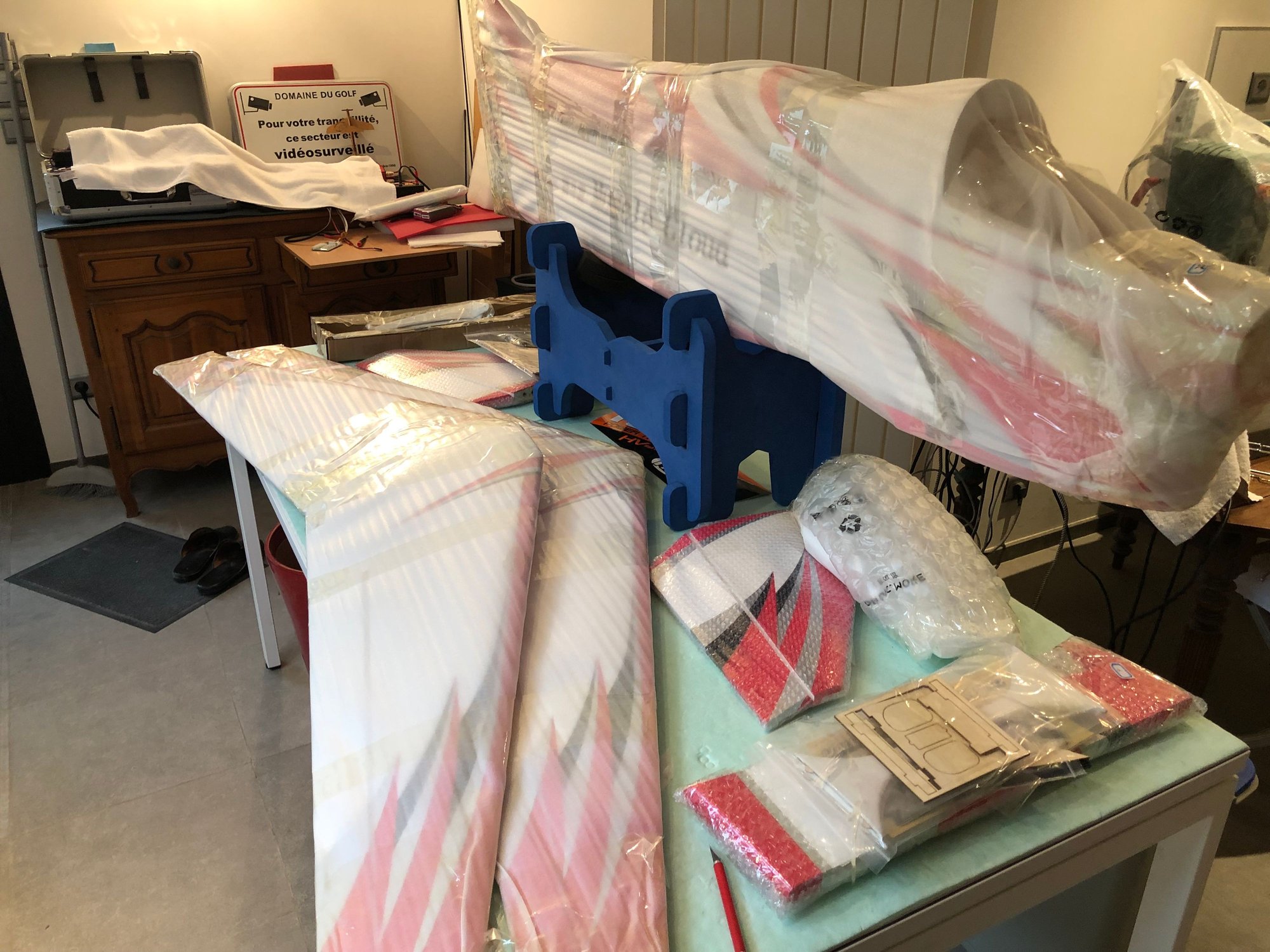
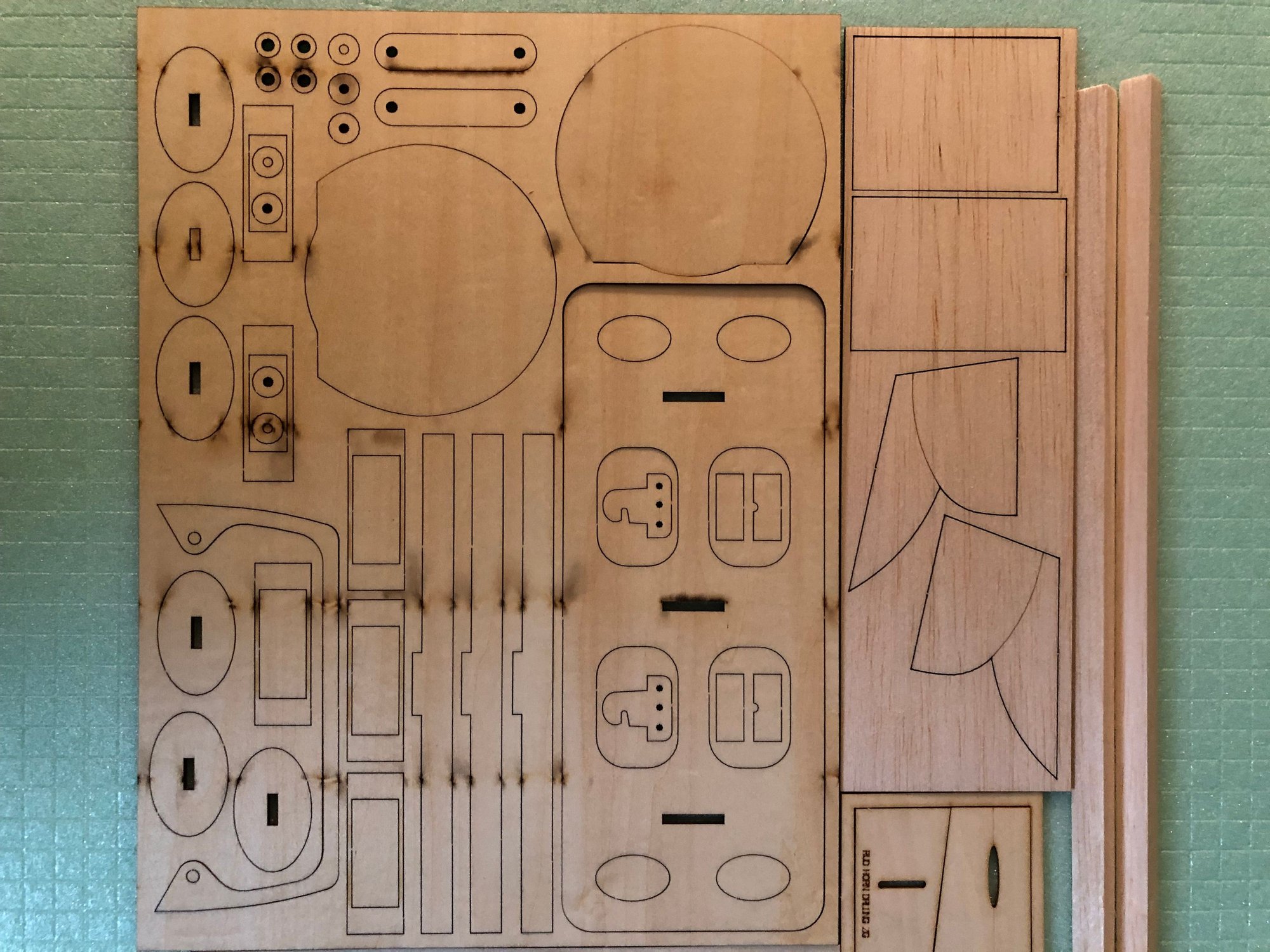
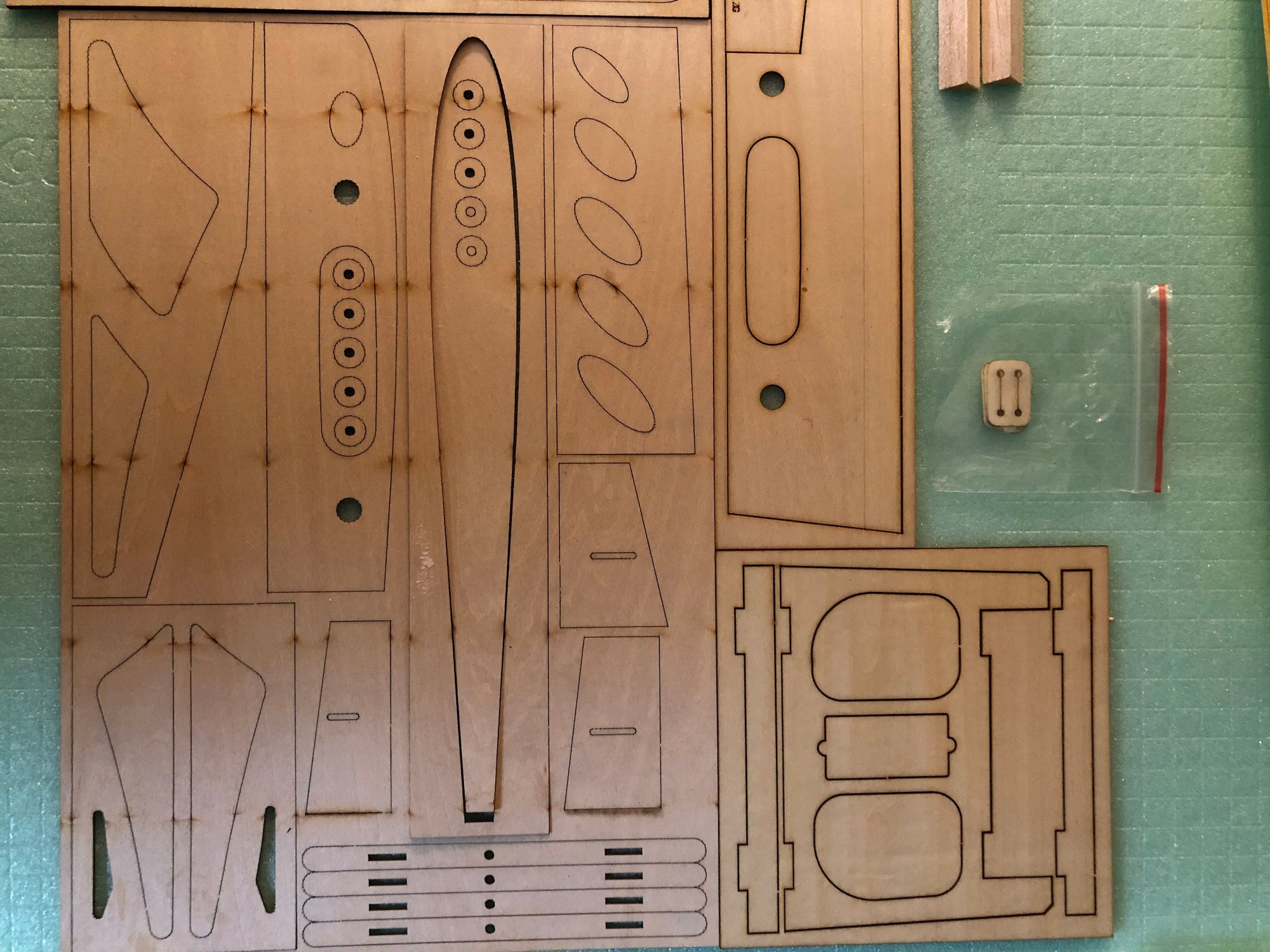
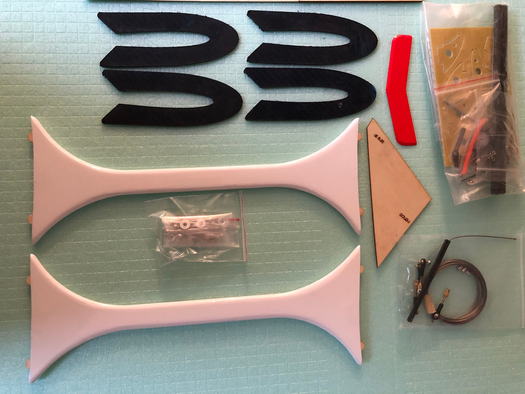
After the IMMORTAL, the SP PASSION, the EPILOGUE and 2 LEADER G , all from BJCRAFT here is the MUSCLE CLOUD build
These are the links to two threads posted on RCU
Bj craft immortal
New bjcraft epilogue
The BJ packaging is perfect, and since the crate has been reinforced, there was not a single damage on the kits I received.
Let's see what we have in this plywood box
Last edited by J-P; 01-30-2025 at 08:05 AM.
The following users liked this post:
doblerizo (01-31-2025)
01-31-2025 | 06:37 AM
#4
Thread Starter
My Feedback: (1)
I started by checking all the parts and components.
Paint job is very good, maybe better that the one on the LeaderG.
The quality of the covering, accuracy and finish is perfect, not a single bubble , nothing to do on the wings or stabs.
Hinges are installed, but not glued.
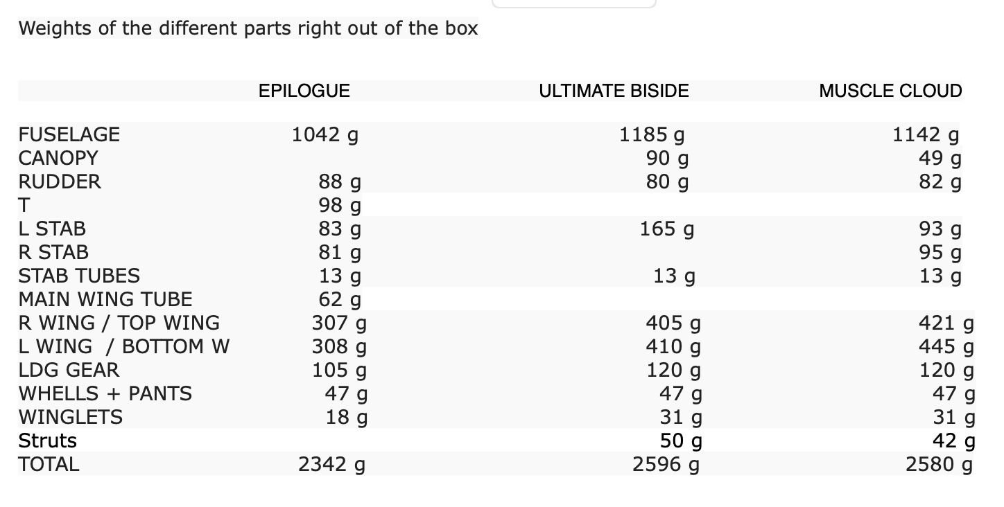
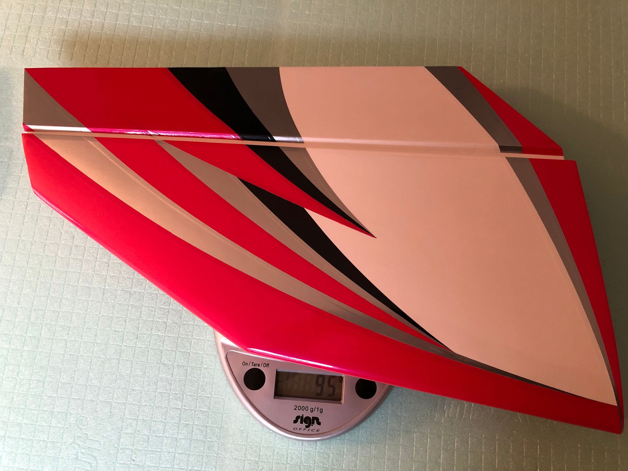
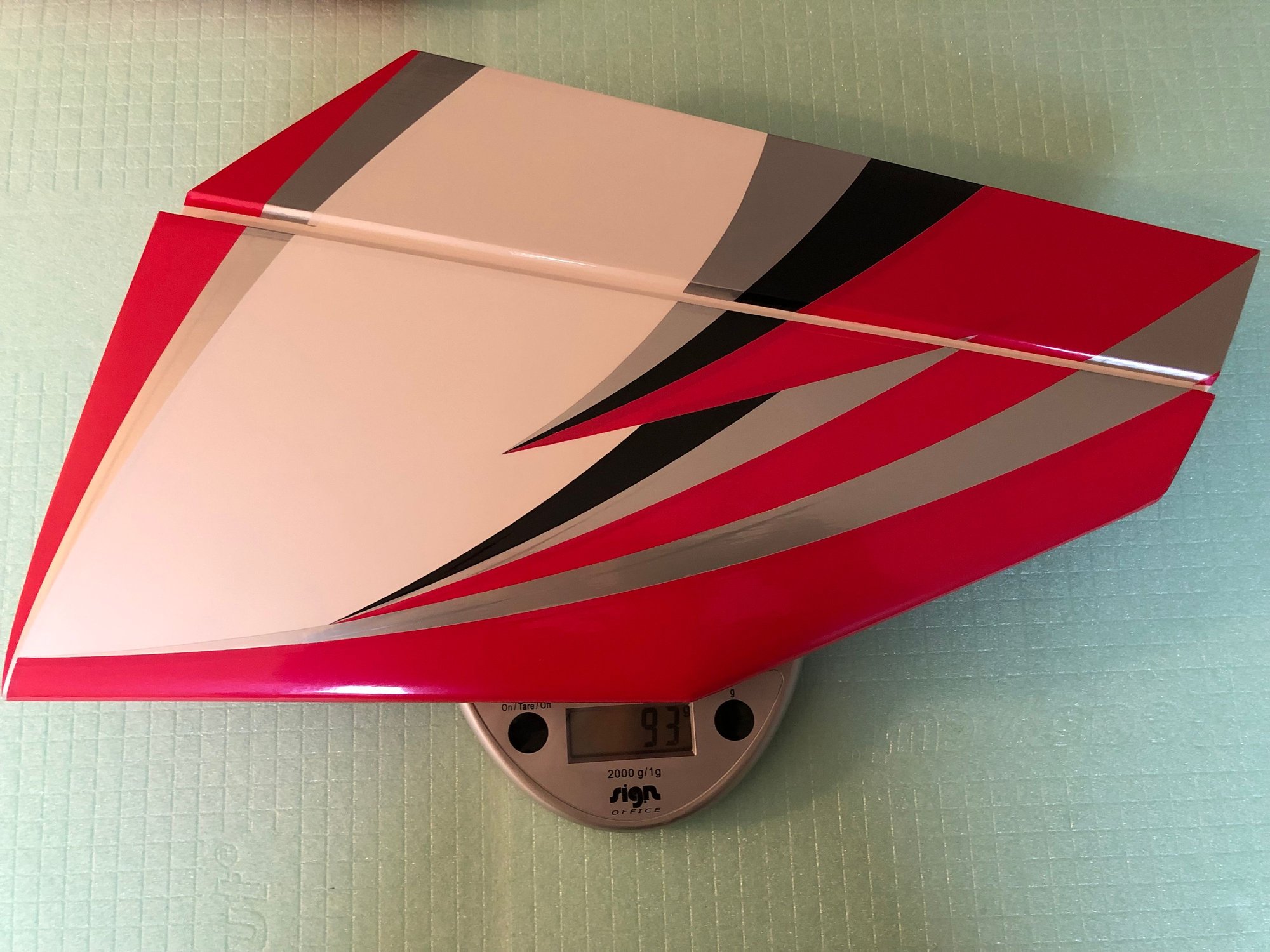
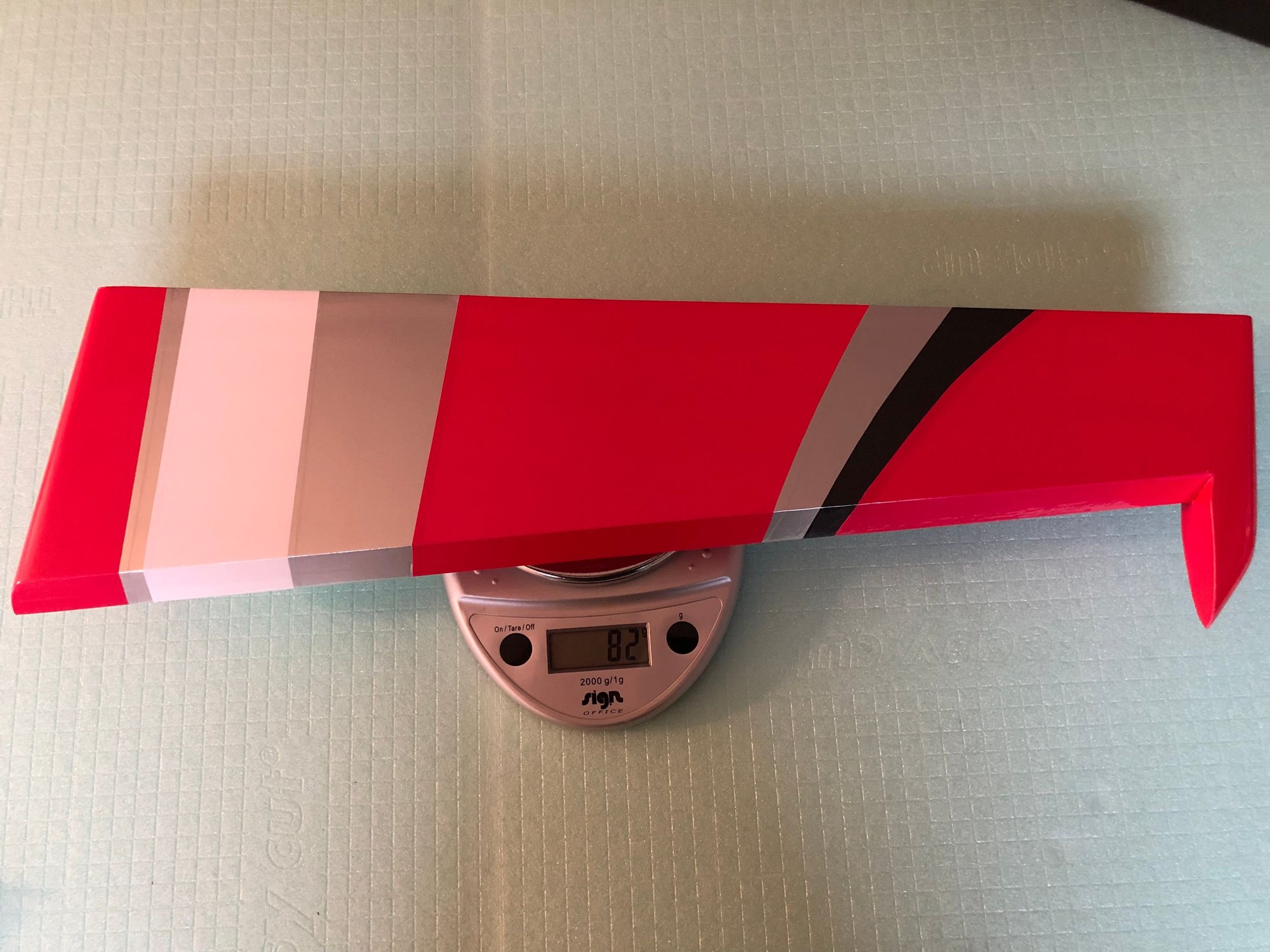
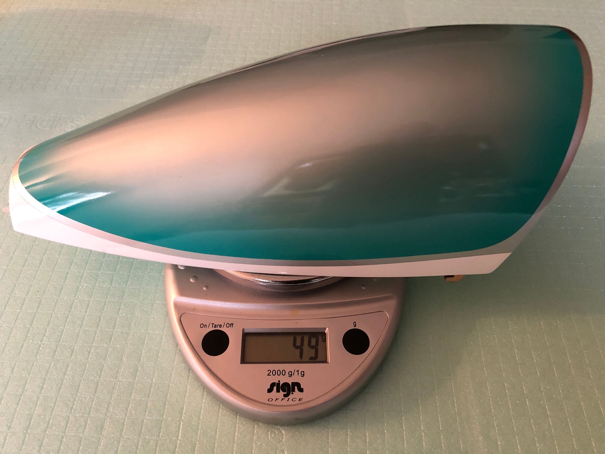
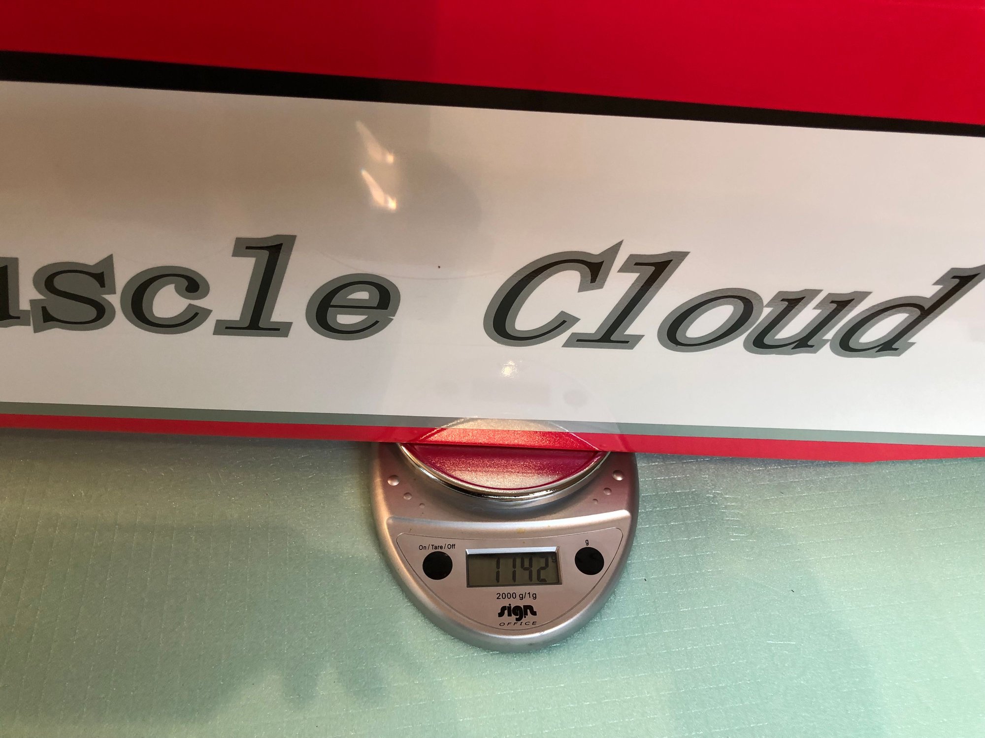
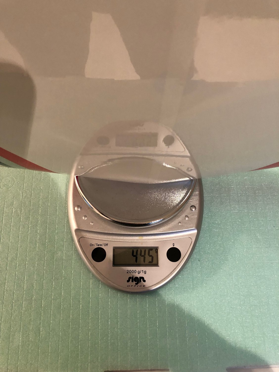
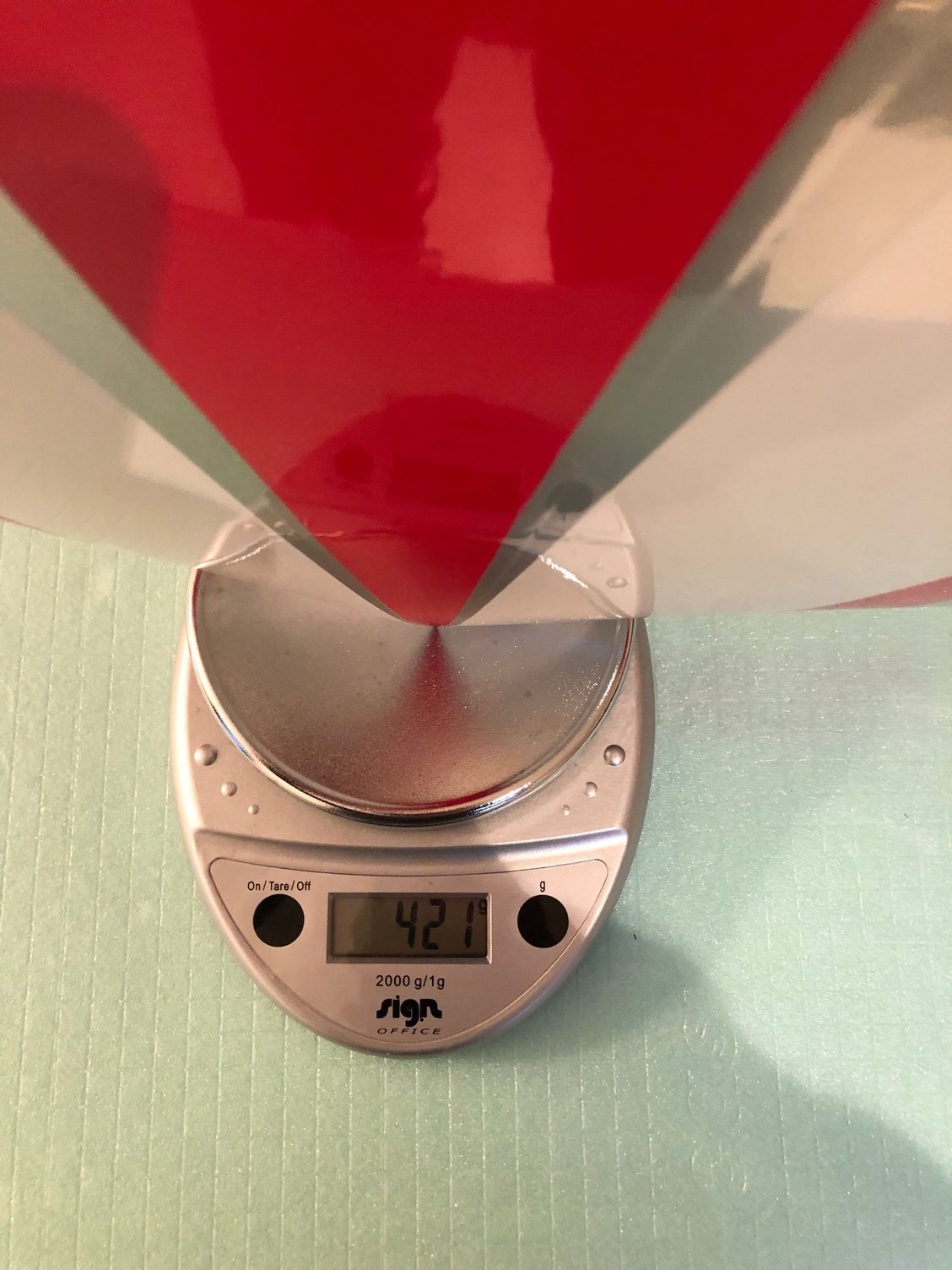
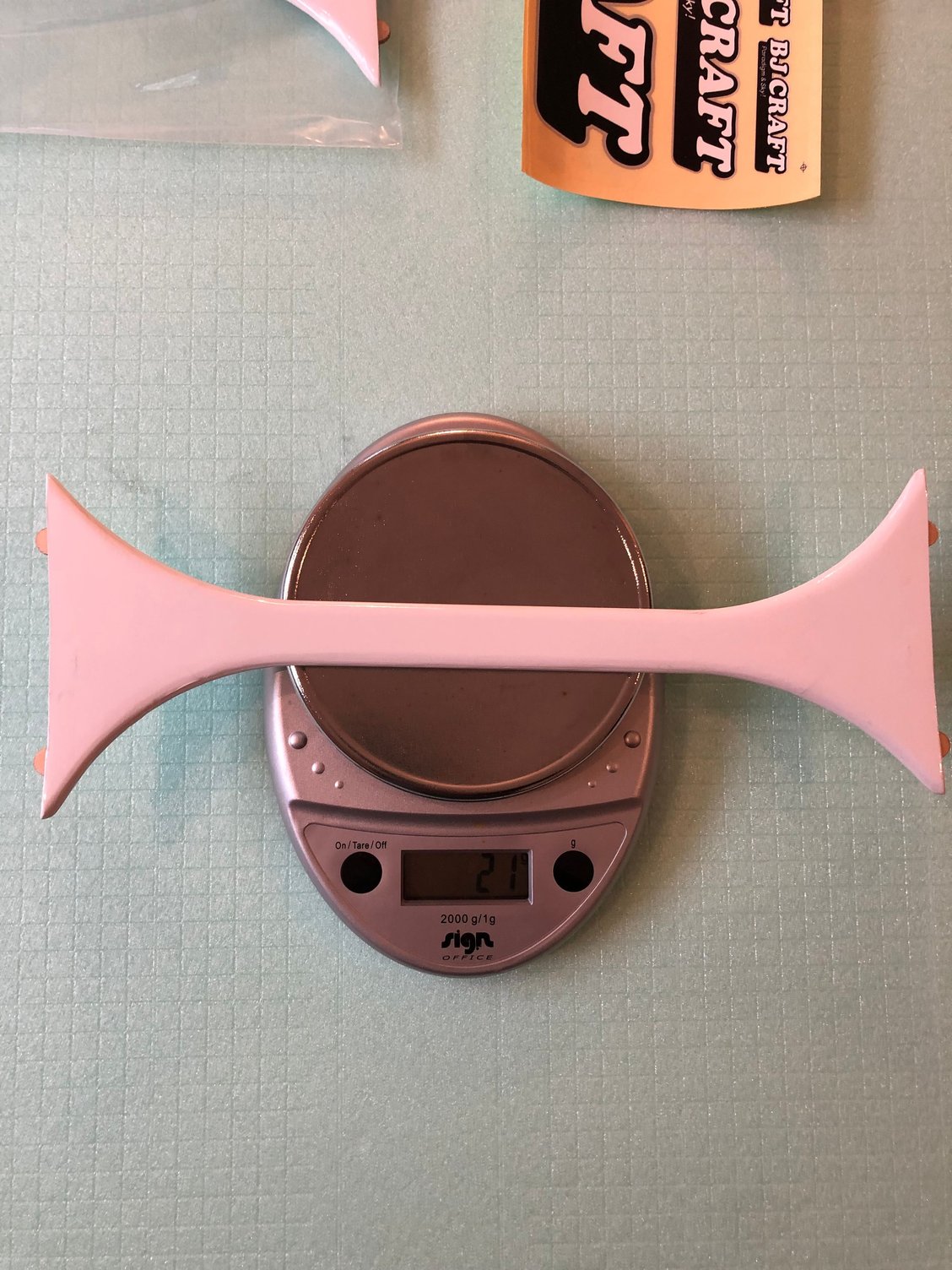
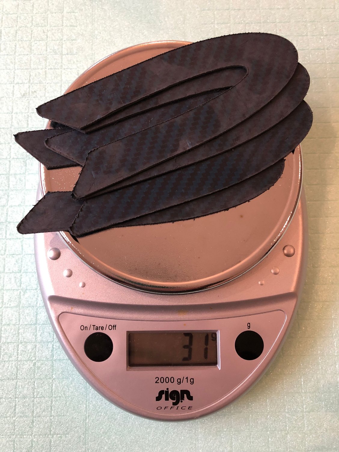
First operation is to weight the components while checking them.
I recorded the weight of the EPILOGUE and of the ULTIMATE BISIDE for comparison
Paint job is very good, maybe better that the one on the LeaderG.
The quality of the covering, accuracy and finish is perfect, not a single bubble , nothing to do on the wings or stabs.
Hinges are installed, but not glued.
First operation is to weight the components while checking them.
I recorded the weight of the EPILOGUE and of the ULTIMATE BISIDE for comparison
 02-02-2025 | 08:41 AM
#6
Thread Starter
My Feedback: (1)
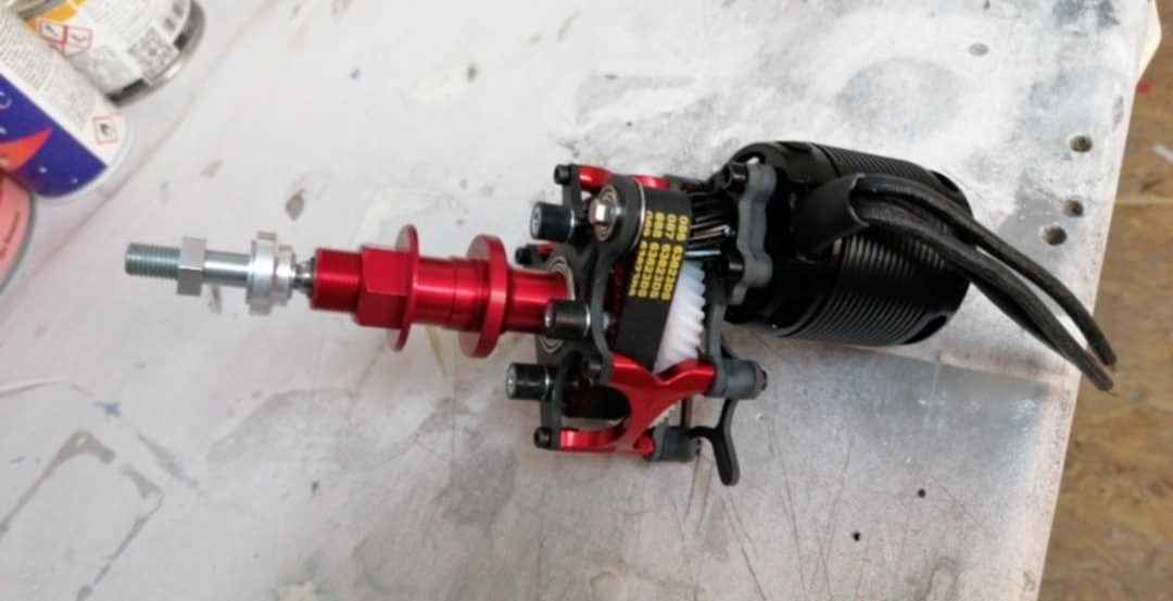
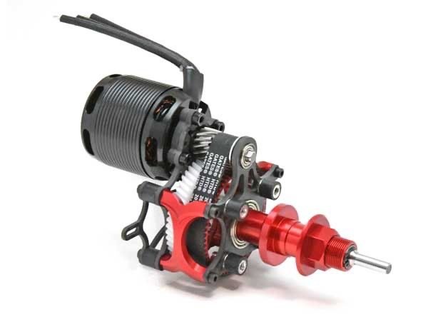
MUSCLE CLOUD equipment
.
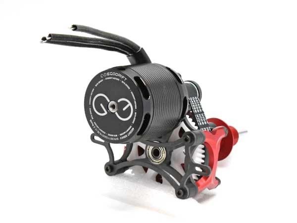
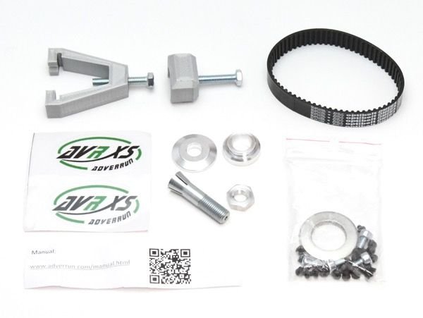
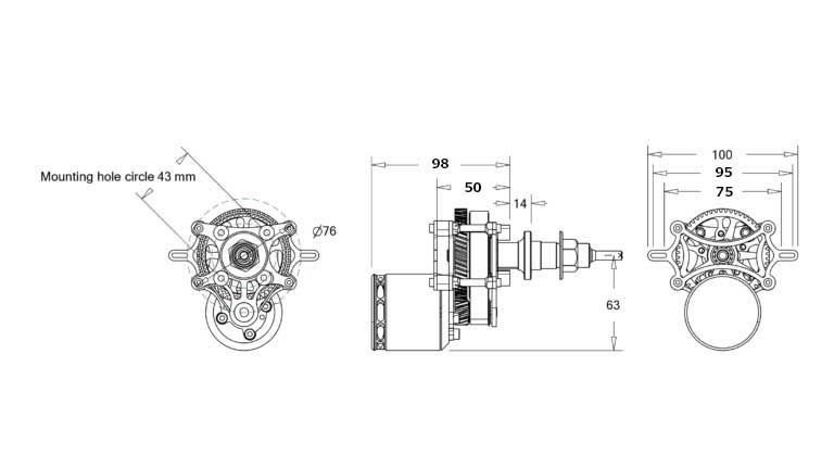
ADVERRUN EGODRIFT V3
Motor EGODRIFT 4025HT 550KV 10 Poles
Weight 550g
Propellers
FALCON F23x20/R23x20
ESC D3
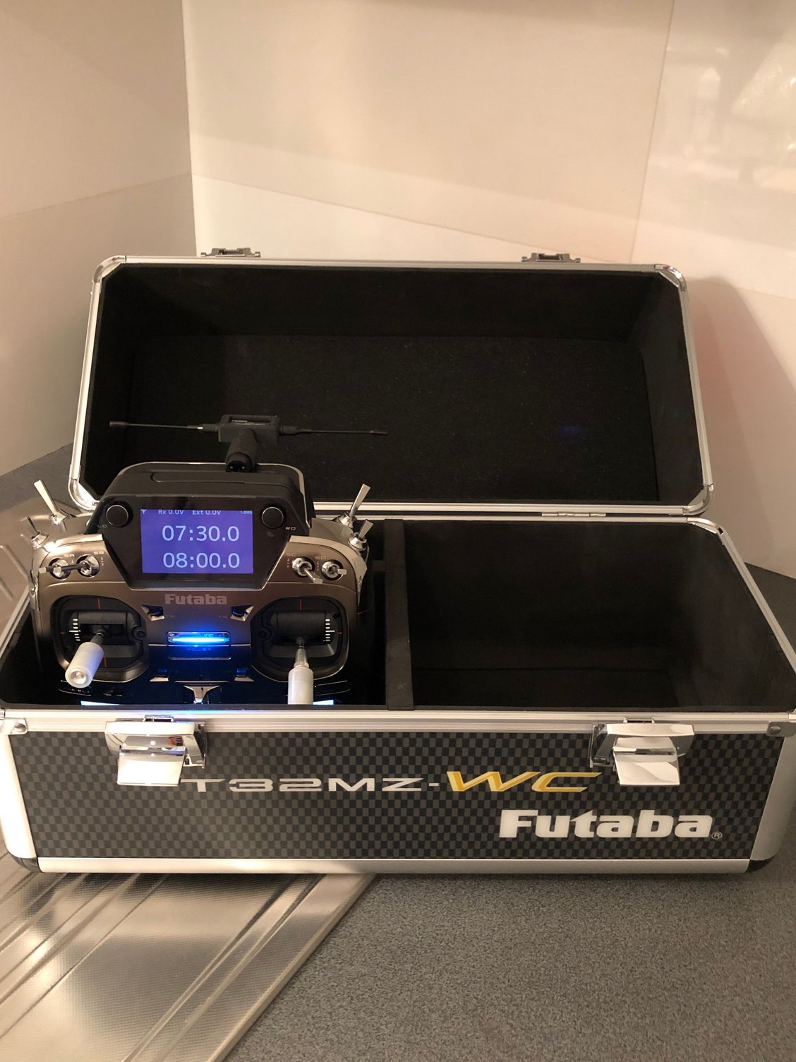
FUTABA 32 MZ WC ( with TM-18 - 900 MHz in USA)
RX R7308SB & R9001SB
Ailerons servos A 600
Elevators servos BLS 173 SV
Rudder servo A 704
Batteries THUNDER POWER F3A 5000 mah
FLIGHT HOBBY landing gear & Wheel pants
Last edited by J-P; 02-02-2025 at 08:55 AM.

 02-03-2025 | 06:23 AM
#8
Thread Starter
My Feedback: (1)
Additional informations about the MUSCLE CLOUD
Wing span is 177 cm
Weight ready to fly 4960 g with an AKIBA battery 5200 mah weighting 1030g
CG varies from 220 to 240 mm from the lower wing dowels
Rudder servo is installed in the fuselage in front of the lower wing trailing edge
Rudder authority is very important and airplane just need a touch of on knife edge
The height of the battery plate is very important to achieve a rudder to aileron zero mix
Elevator horn length is 13mm.
Aileron horn length is 20mm.
For the prop selection, seems large diameter give the best results 23, 23.5 or 24 / 20 F&R
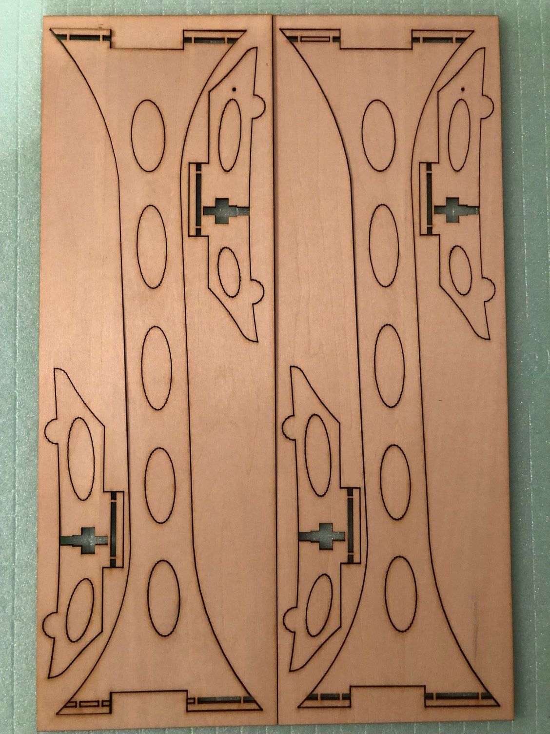
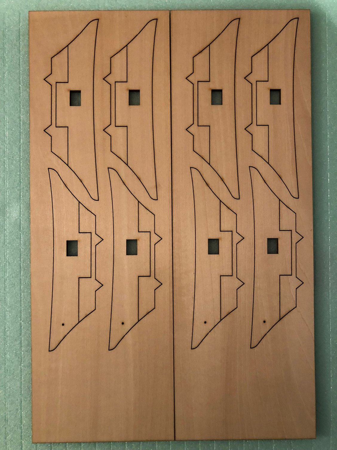
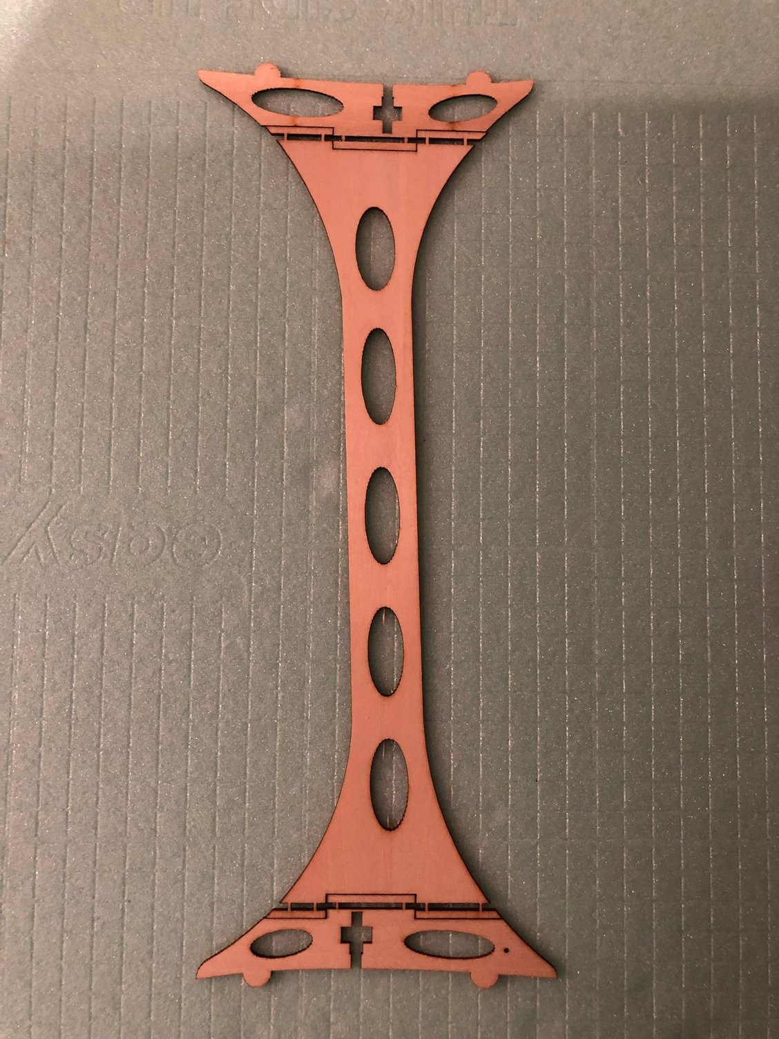
The height of the fuselage to compare with the LEADER G can be see on this pic with the difference size of the strutsQuick struts have already been developed and tested and will be offered in the future. It’s a kit to assemble
Wings fences are included in the kit and related with spin entry only according BJ
“ It shall be necessary for thin air, high altitude flying field, or heavier nose heavy setting
In Europe where temperature is lower than in Asia for example, it shall not be needed.
Japanese pilots do not use it so in Europe as well.
But may be needed in Singapore or Zhuhai. "
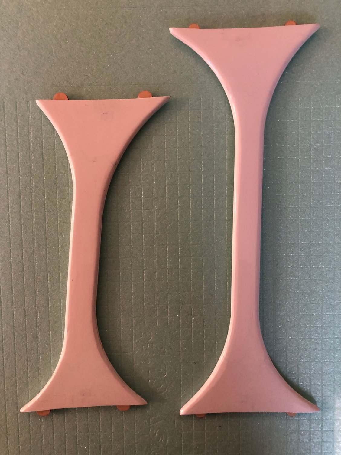
LEADER G & MUSCLE CLOUD STRUTS
Wing span is 177 cm
Weight ready to fly 4960 g with an AKIBA battery 5200 mah weighting 1030g
CG varies from 220 to 240 mm from the lower wing dowels
Rudder servo is installed in the fuselage in front of the lower wing trailing edge
Rudder authority is very important and airplane just need a touch of on knife edge
The height of the battery plate is very important to achieve a rudder to aileron zero mix
Elevator horn length is 13mm.
Aileron horn length is 20mm.
For the prop selection, seems large diameter give the best results 23, 23.5 or 24 / 20 F&R
The height of the fuselage to compare with the LEADER G can be see on this pic with the difference size of the strutsQuick struts have already been developed and tested and will be offered in the future. It’s a kit to assemble
Wings fences are included in the kit and related with spin entry only according BJ
“ It shall be necessary for thin air, high altitude flying field, or heavier nose heavy setting
In Europe where temperature is lower than in Asia for example, it shall not be needed.
Japanese pilots do not use it so in Europe as well.
But may be needed in Singapore or Zhuhai. "
LEADER G & MUSCLE CLOUD STRUTS
02-04-2025 | 06:06 AM
#9
Thread Starter
My Feedback: (1)
I started this time with the fuselage
The stabilizer is fixed with no adjustable incidence device
So using it at zero reference, I checked the value of the down-thrust fuselage : it's at zero
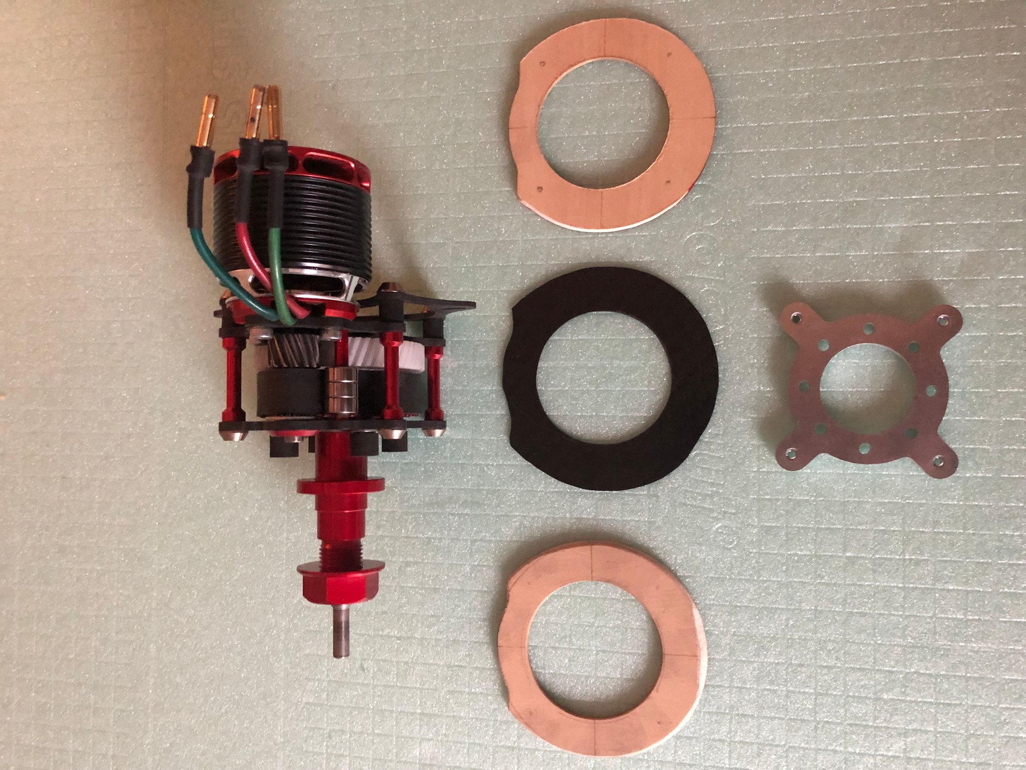
For the engine mount, there are for me two options :
- to use the parts included in the kit, adding a thin carbon plate
- to have a cnc plywood part fitting the inner shape of the fuselage
It's what I did with the LEADER G
The diameter of the MUSCLE CLOUD engine mount is smaller than one of the LEADER G, and there is not too much material left using the same design adapted.
For the Leader G the engine mount was designed to accommodate both the ADVERRUN and the TMCR
Didn't decided yet if I'll do the same, so I will see later
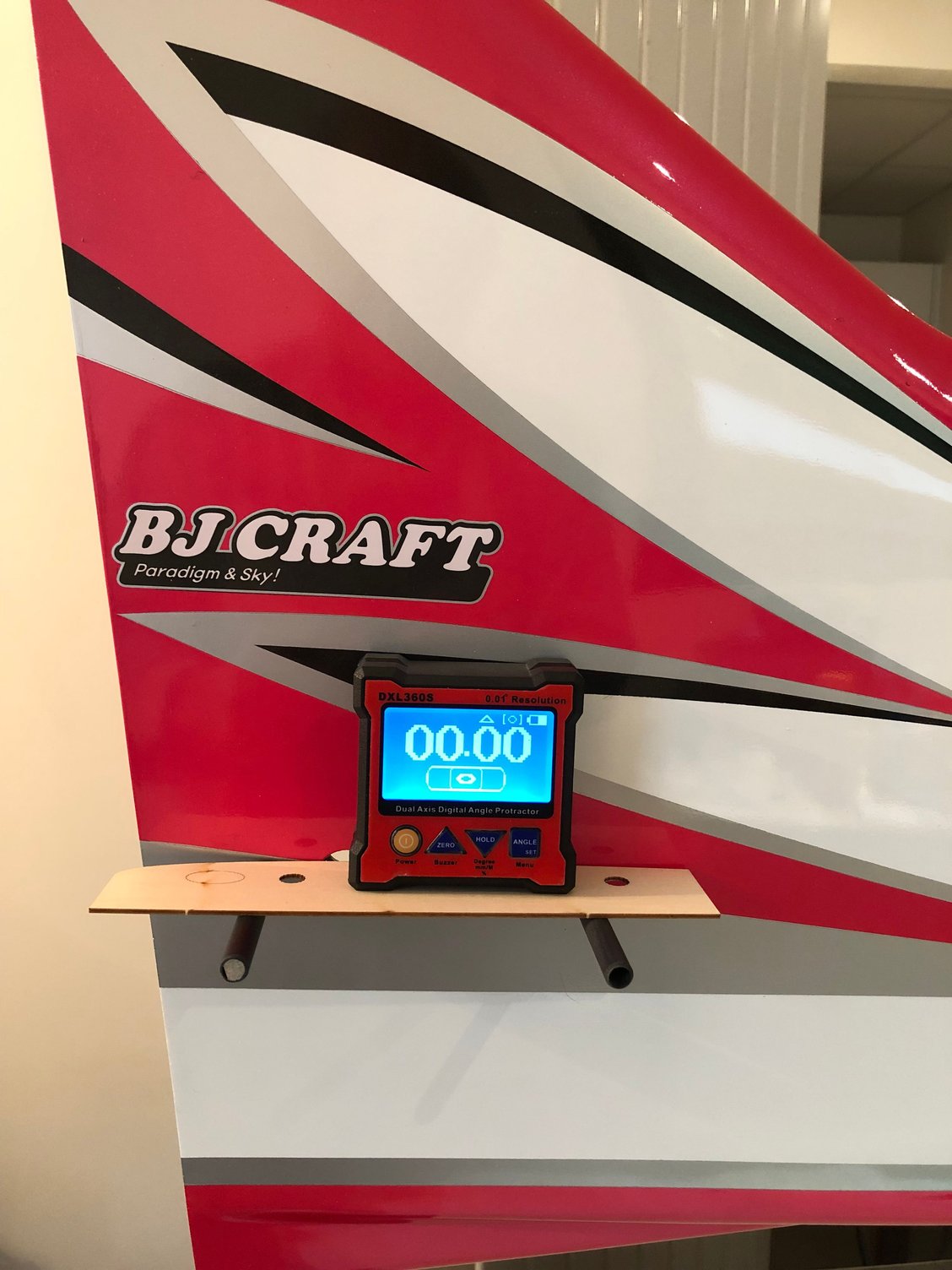
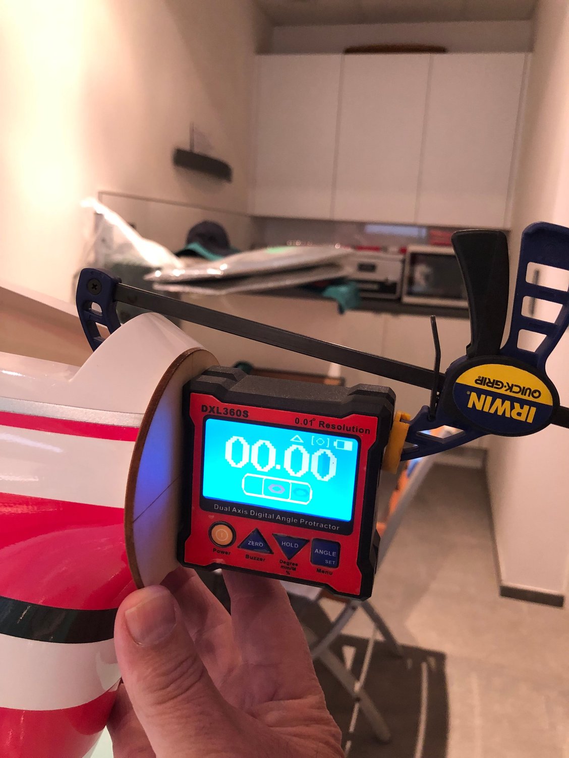
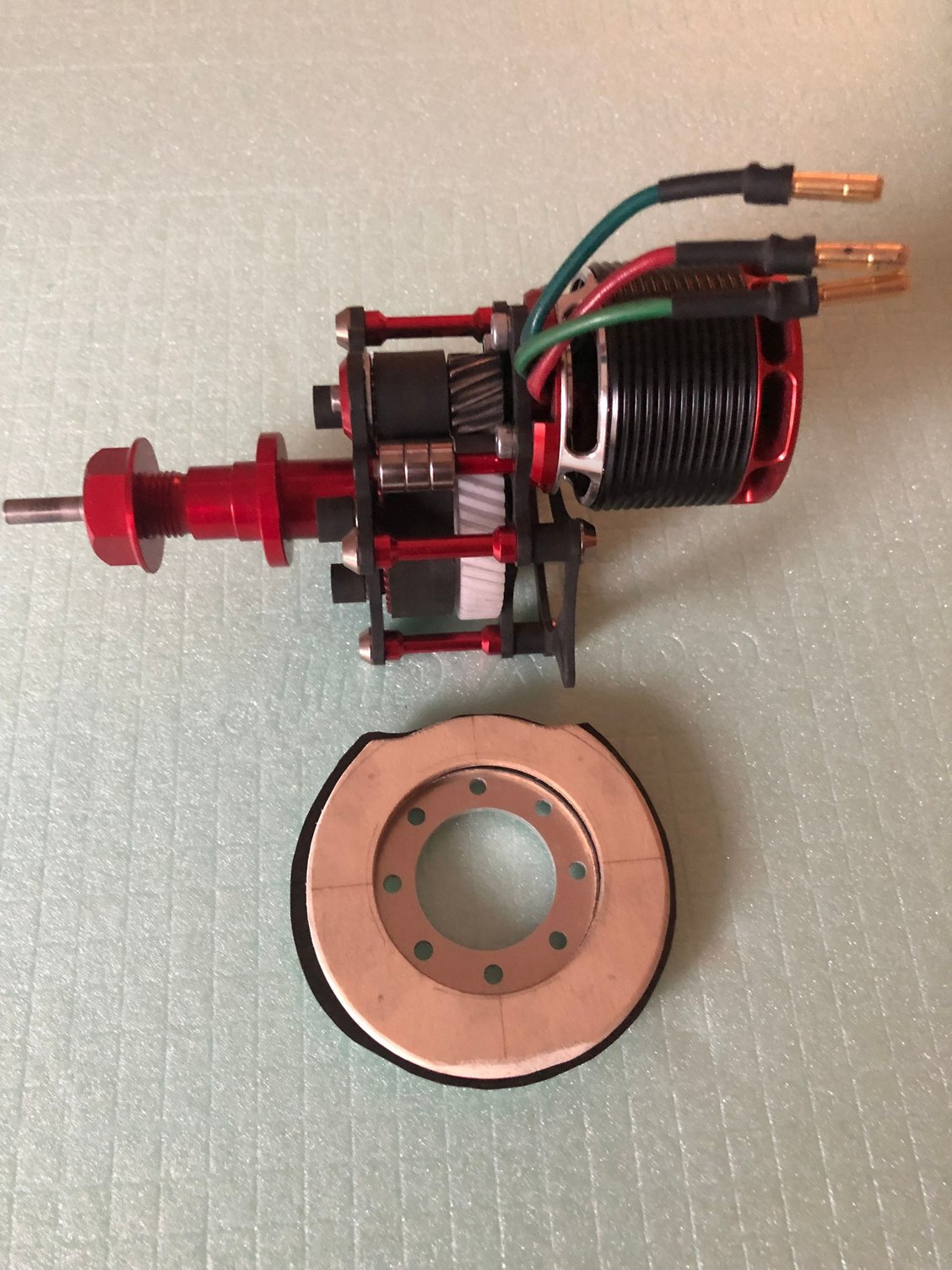
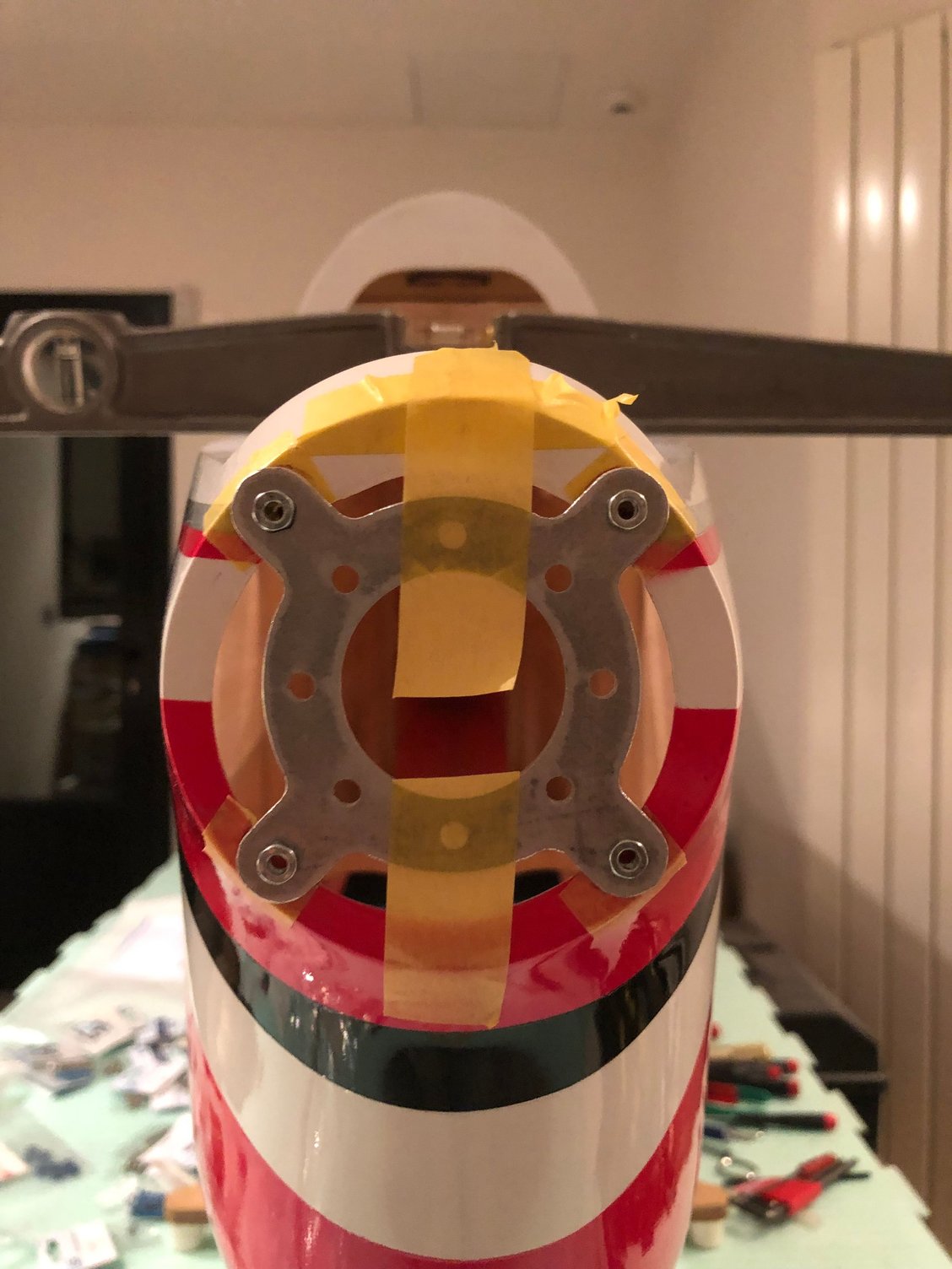

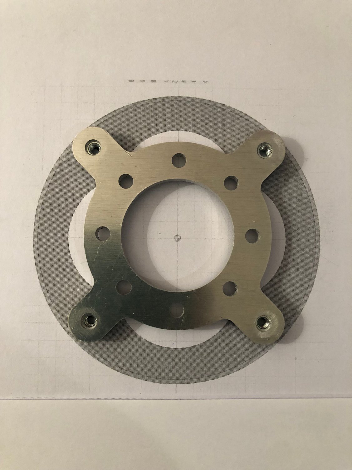
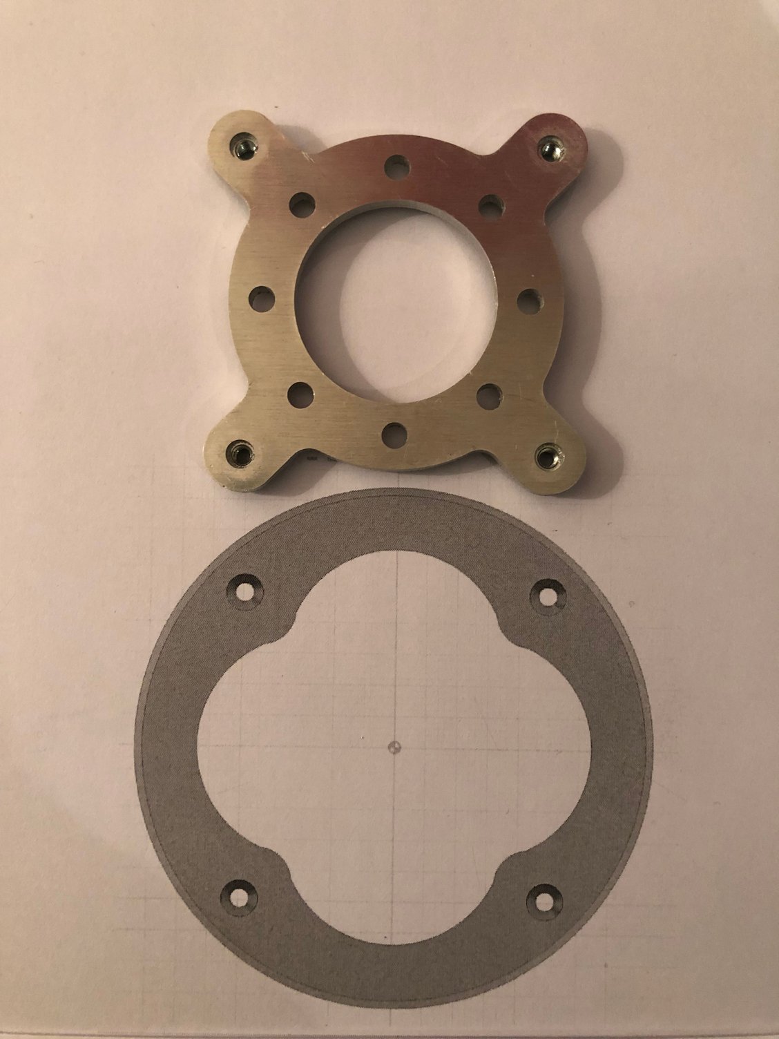


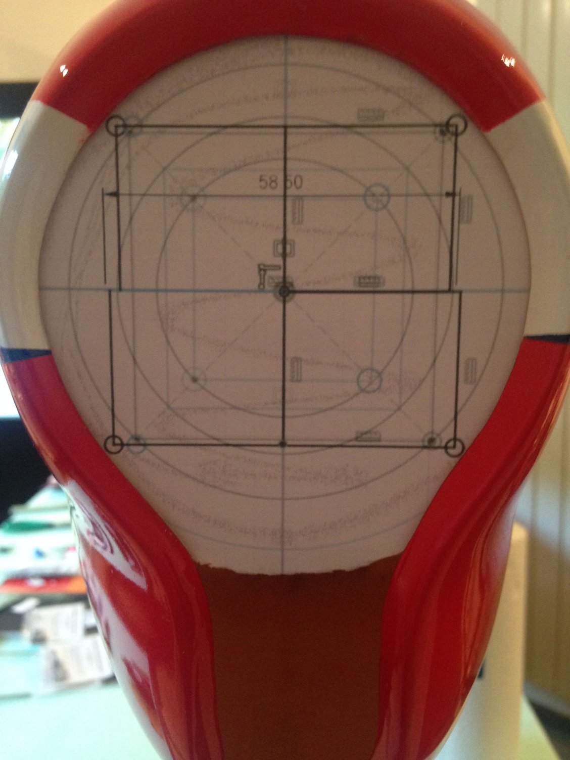
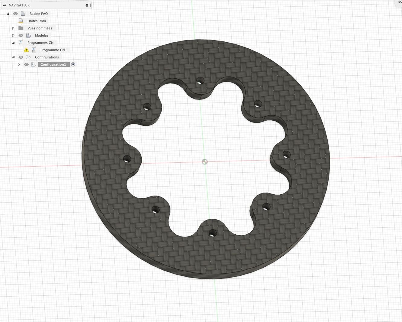
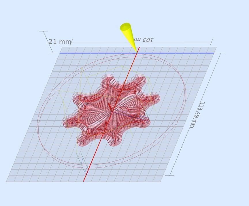
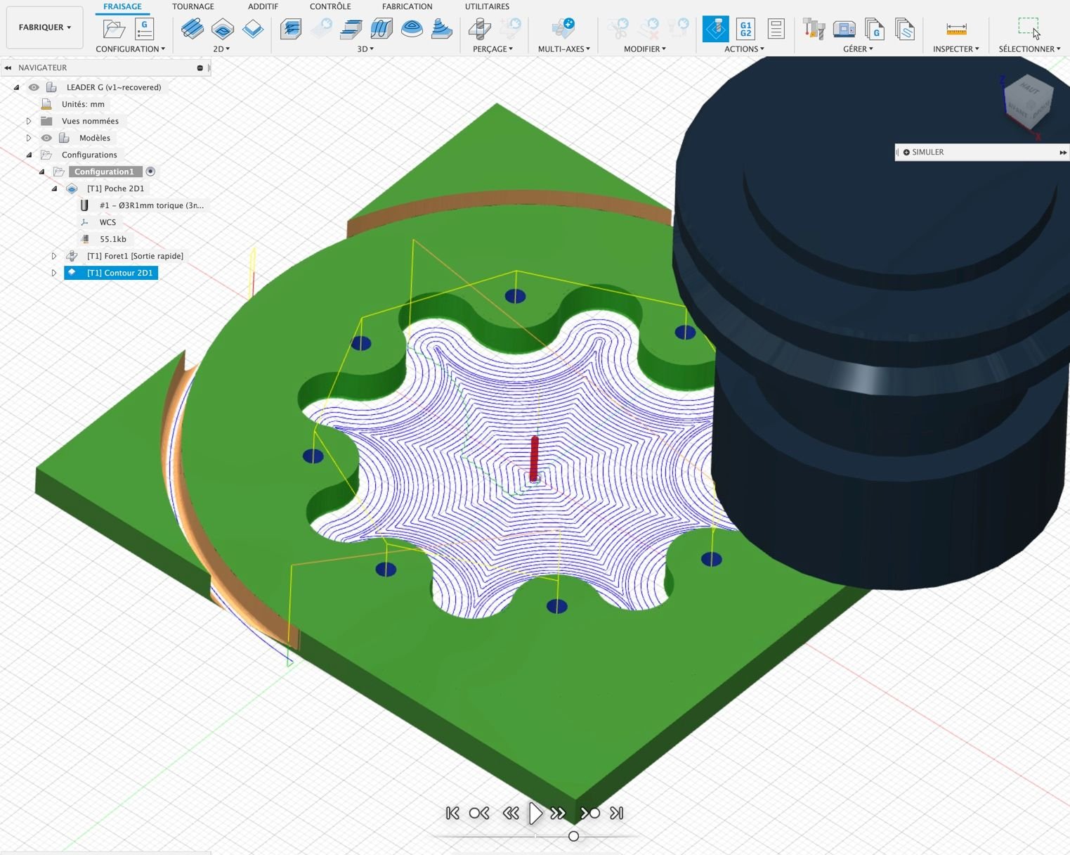
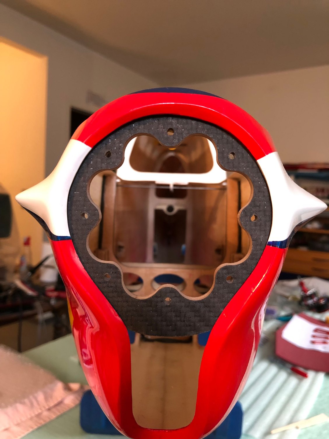
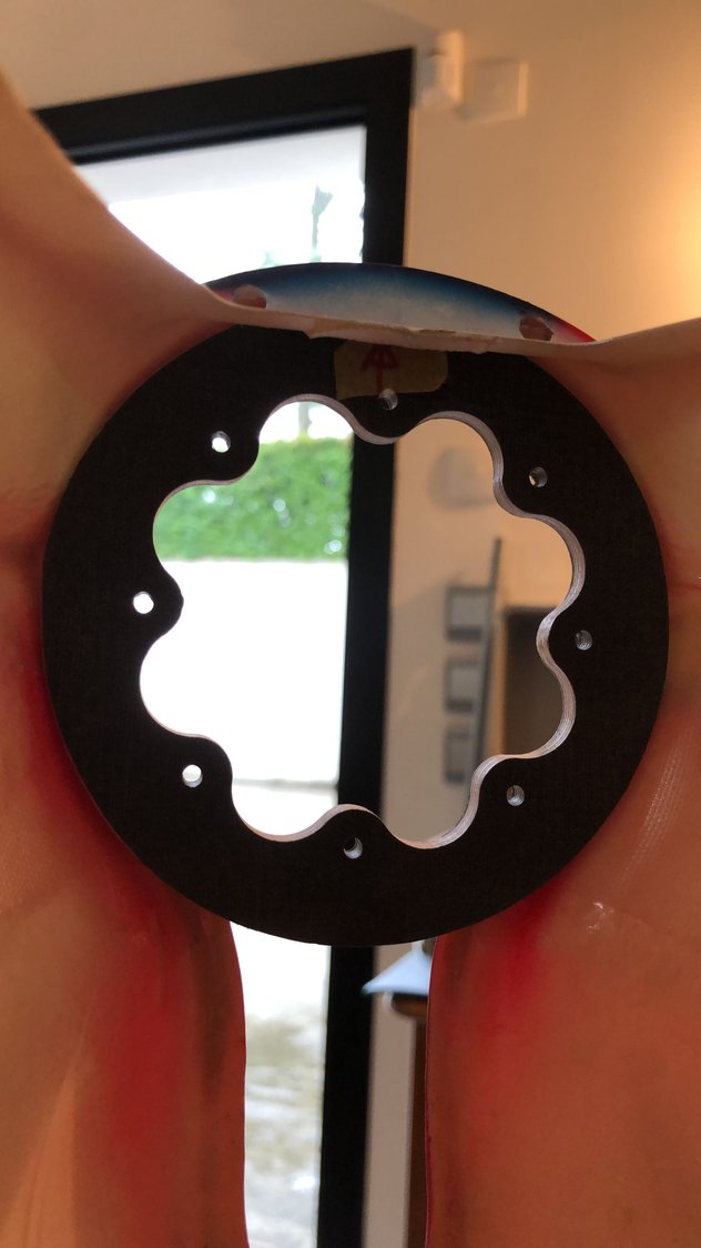
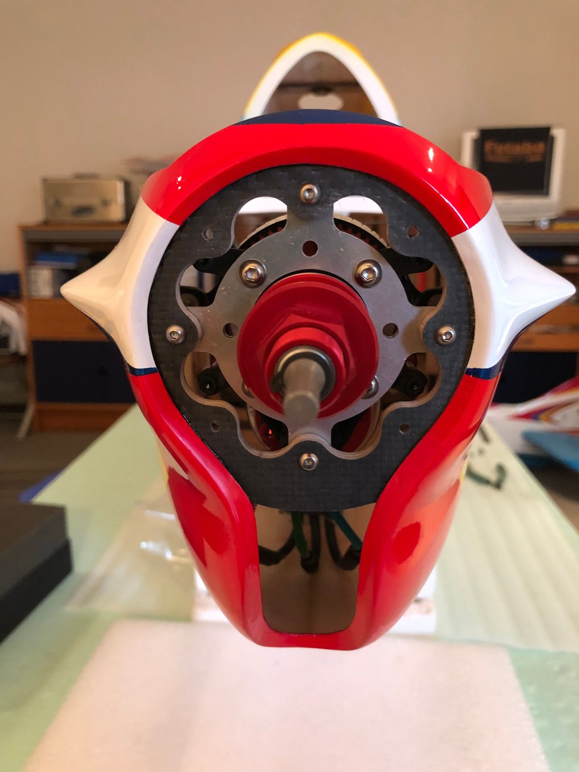
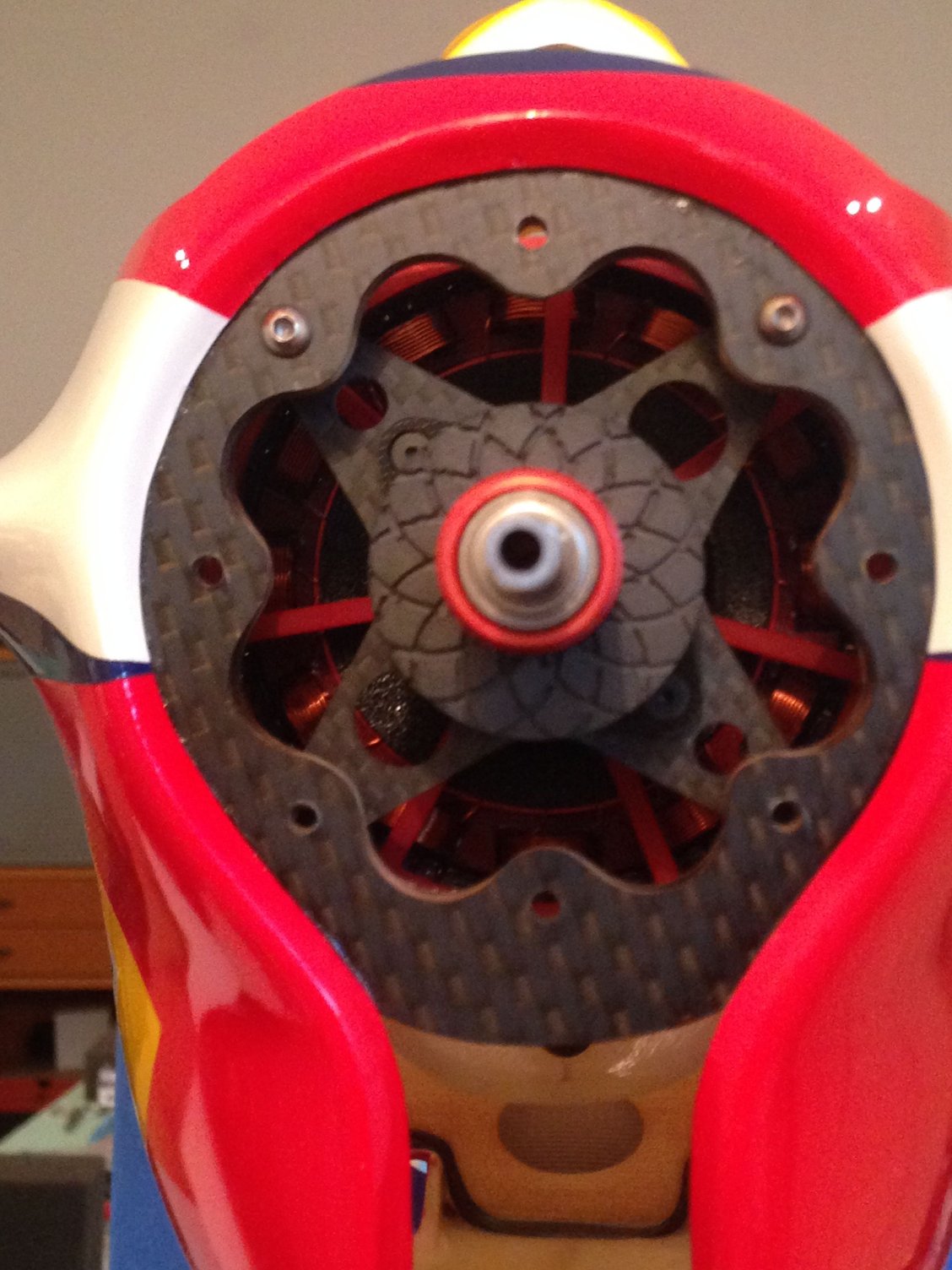
The stabilizer is fixed with no adjustable incidence device
So using it at zero reference, I checked the value of the down-thrust fuselage : it's at zero
For the engine mount, there are for me two options :
- to use the parts included in the kit, adding a thin carbon plate
- to have a cnc plywood part fitting the inner shape of the fuselage
It's what I did with the LEADER G
The diameter of the MUSCLE CLOUD engine mount is smaller than one of the LEADER G, and there is not too much material left using the same design adapted.
For the Leader G the engine mount was designed to accommodate both the ADVERRUN and the TMCR
Didn't decided yet if I'll do the same, so I will see later
02-12-2025 | 05:39 AM
#10
Thread Starter
My Feedback: (1)
As I didn’t had a lot of information about the plane, I watched on YouTube some videos posted by Shoichi Fujita, co designer with BJ of the Muscle Cloud, specially the last one showing the specs.
Always interesting ….
You will notice that the rudder servo initially in the tail is now positioned close to the trailing edge of the wings in the fuselage.
Fujita decided to reinforce the front part of the fuselage with carbon, which I already did with glass cloth
As you can see on the picture of his engine mount, there is not too much material left.
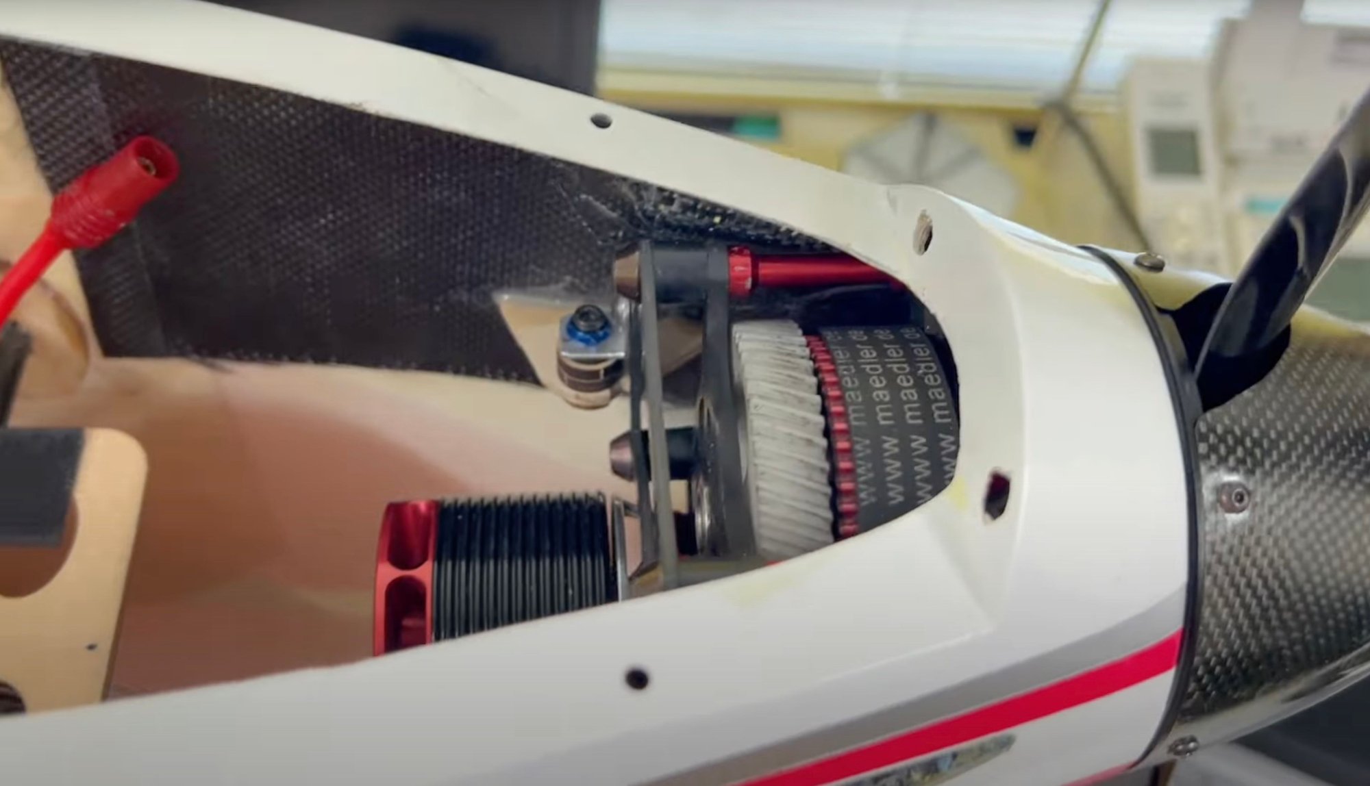
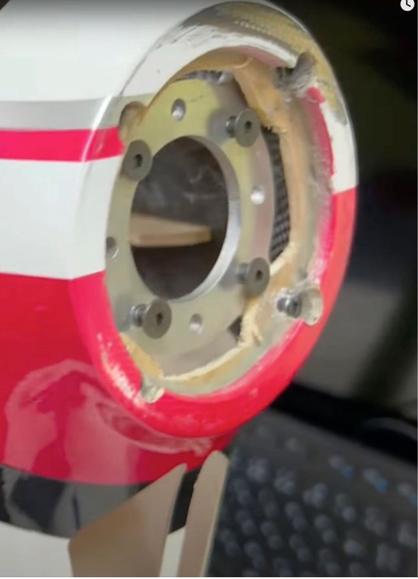
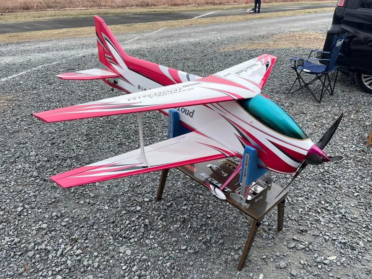

Always interesting ….
You will notice that the rudder servo initially in the tail is now positioned close to the trailing edge of the wings in the fuselage.
Fujita decided to reinforce the front part of the fuselage with carbon, which I already did with glass cloth
As you can see on the picture of his engine mount, there is not too much material left.
The following users liked this post:
wattsup (03-30-2025)
02-12-2025 | 07:05 AM
#11
Thread Starter
My Feedback: (1)
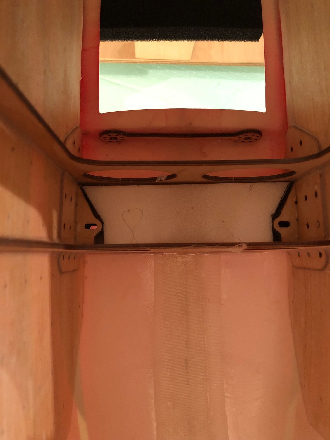
First thing I did with the fuselage was to reinforced for rigidity purpose the nose of the fuselage with a 5 cm width glass cloth.
Right and left sides, bottom of fuselage from the nose ring to the landing gear box.
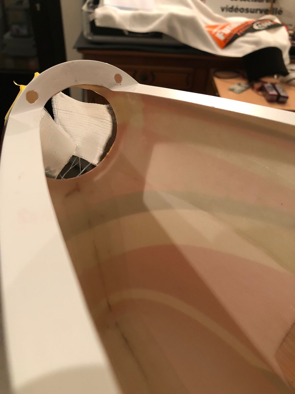
Then I worked on the air intake on the front part of the fuselage, and the air exit at the rear, in the tail post, that has been sufficient for an adequate ventilation until 30 C
With the D3 at 45 degrees in the air intake, temperatures of batteries on the Leader G with the same vents exits were not a concern
Maybe in hot countries an extra exit underneath the fuselage is necessary as done on Fujita model and recommended by BJ
I’ts why I add additional vent exits at the rear of the fuselage …. more sexy than the holes in the bottom of the fuselage 😀
The question is how much is the increase in weight with the glass cloth reinforcement ?
+ 14 g / 1/2 ounce after the ventilation done compare to the initial weight.
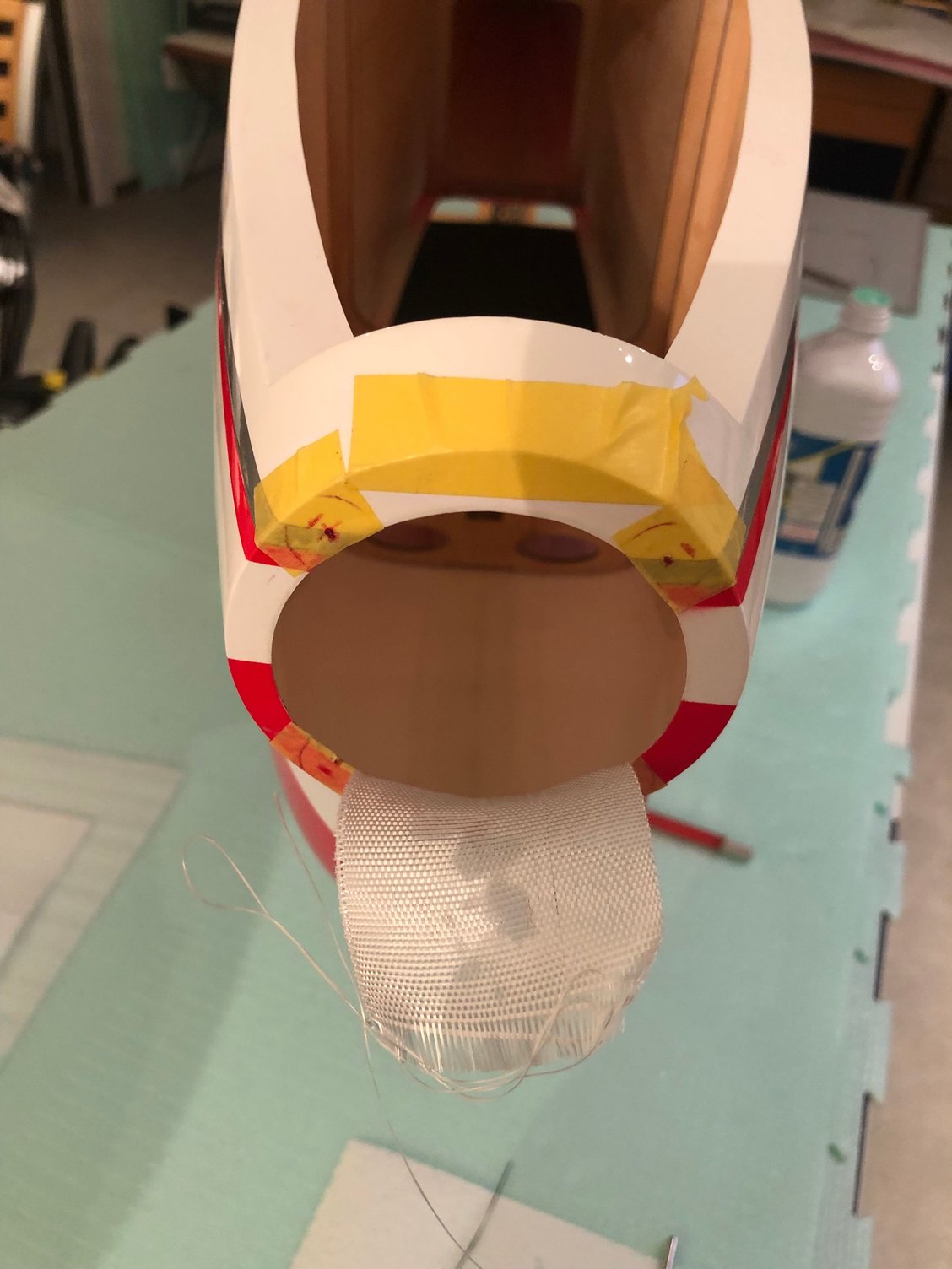

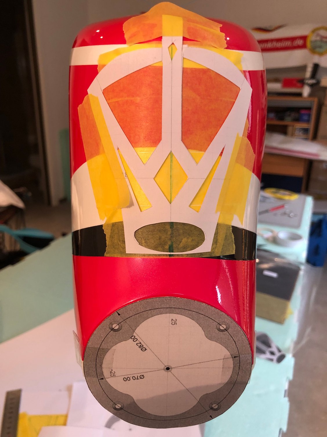
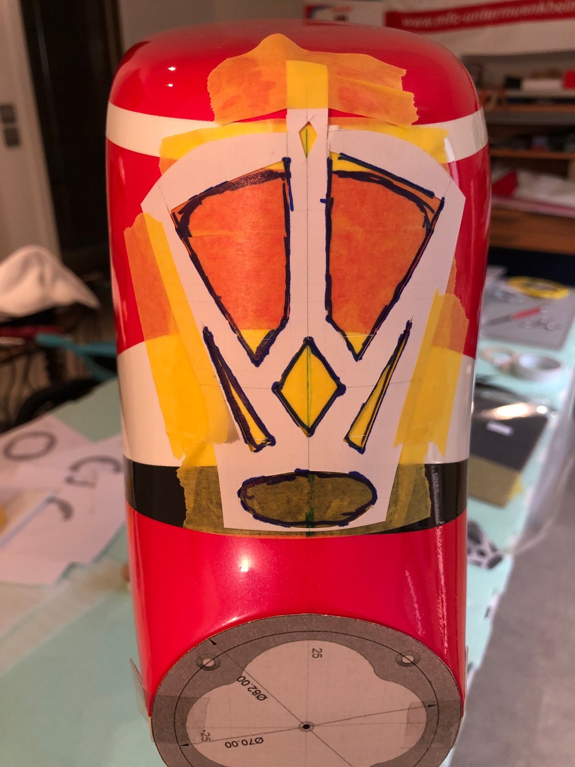
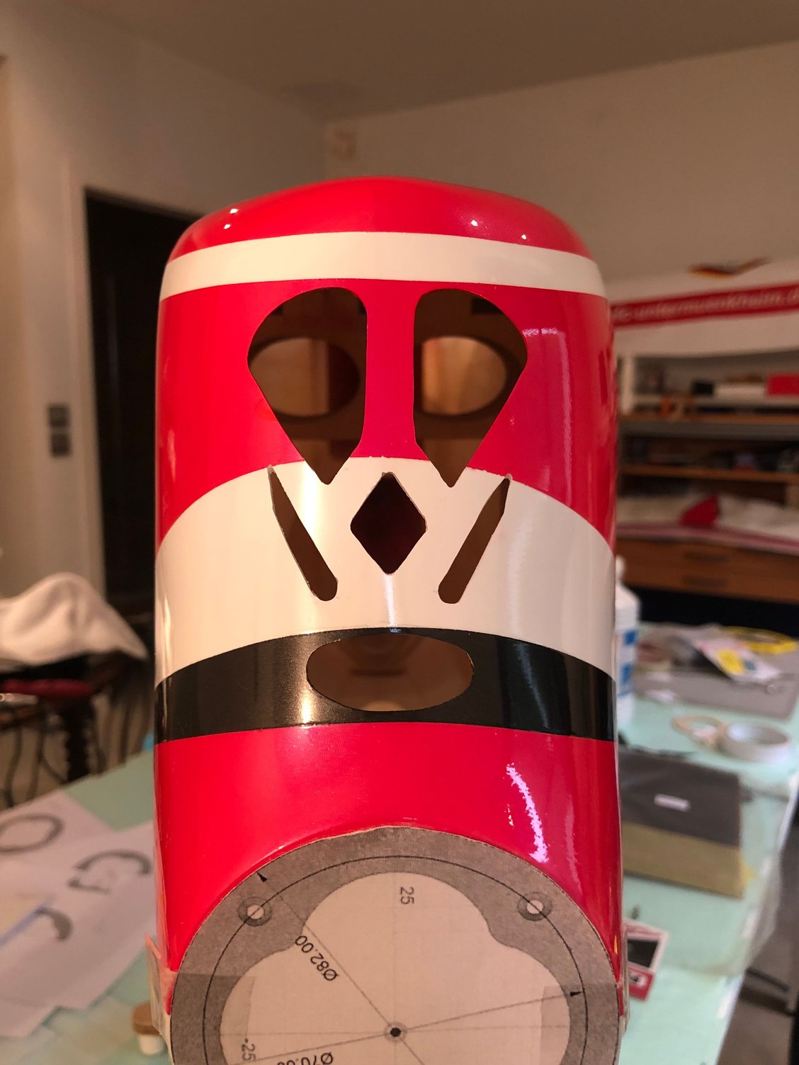
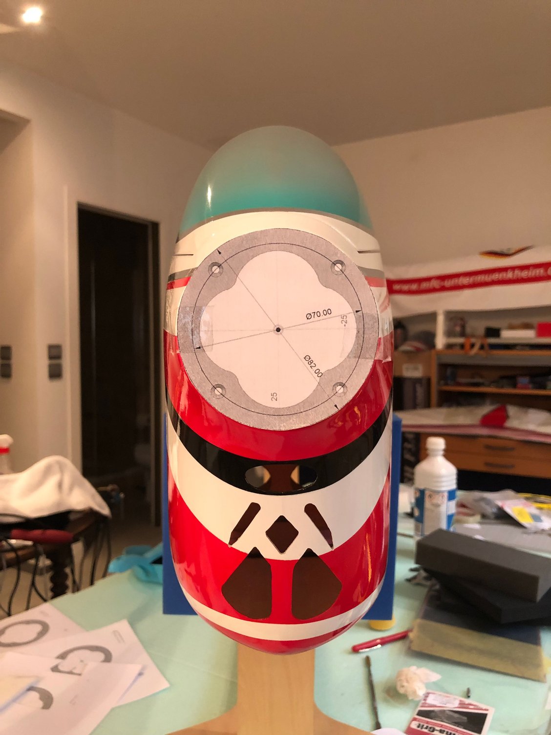

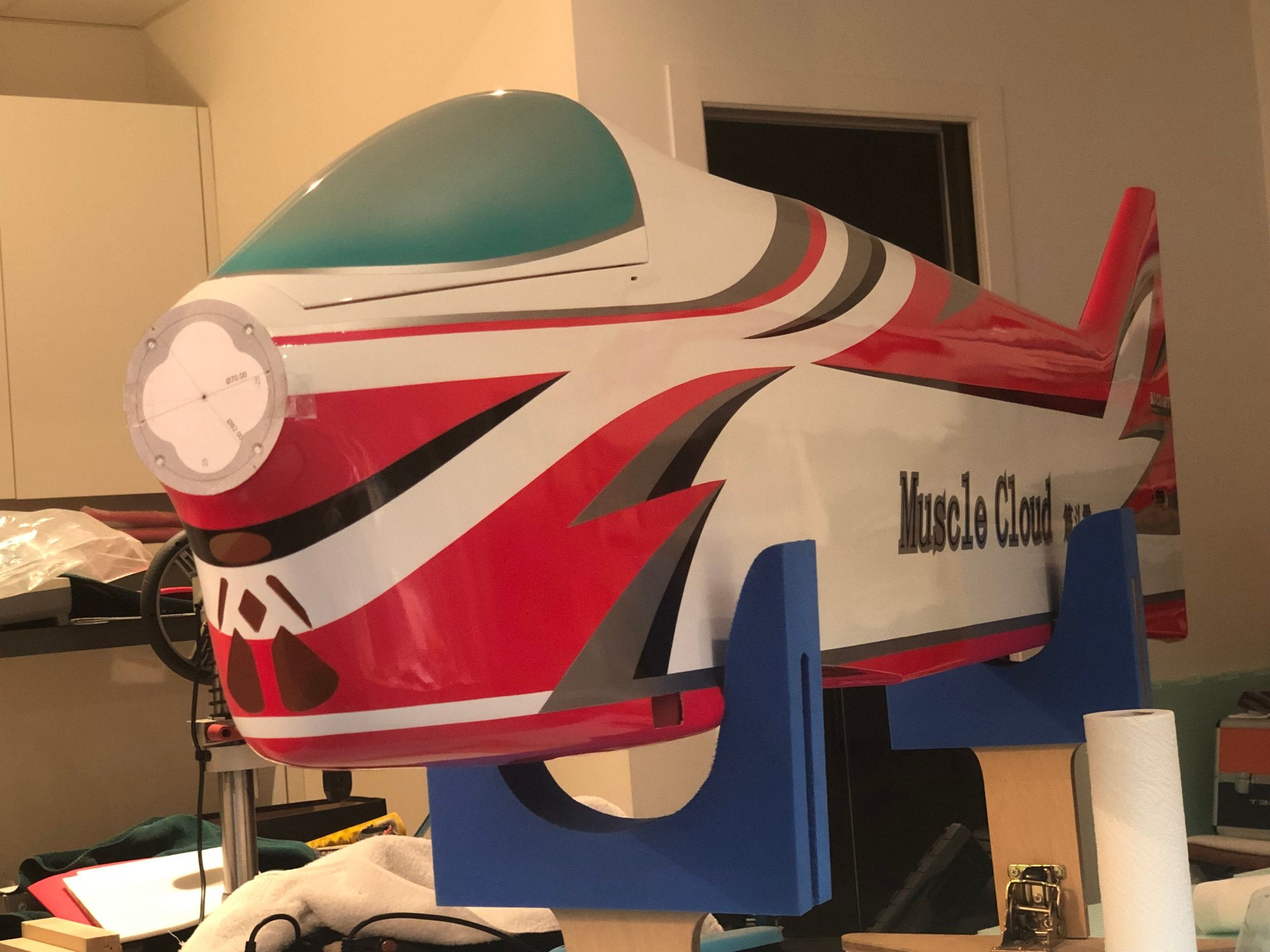
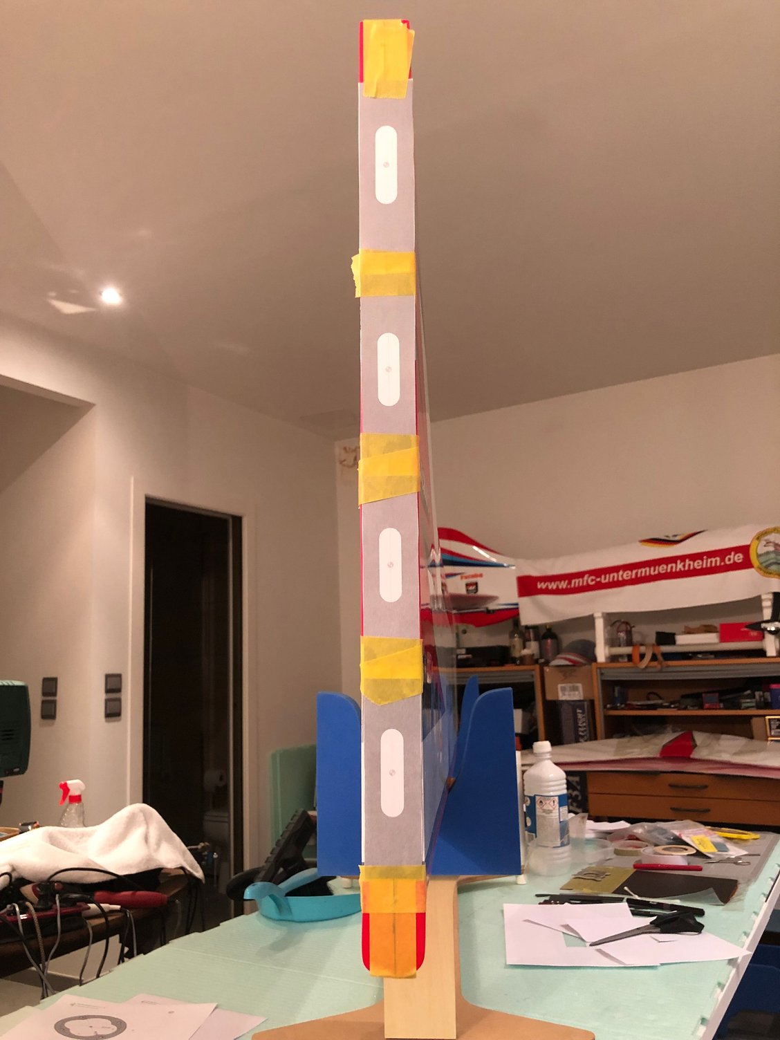
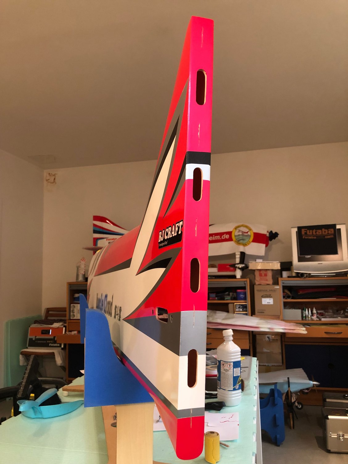
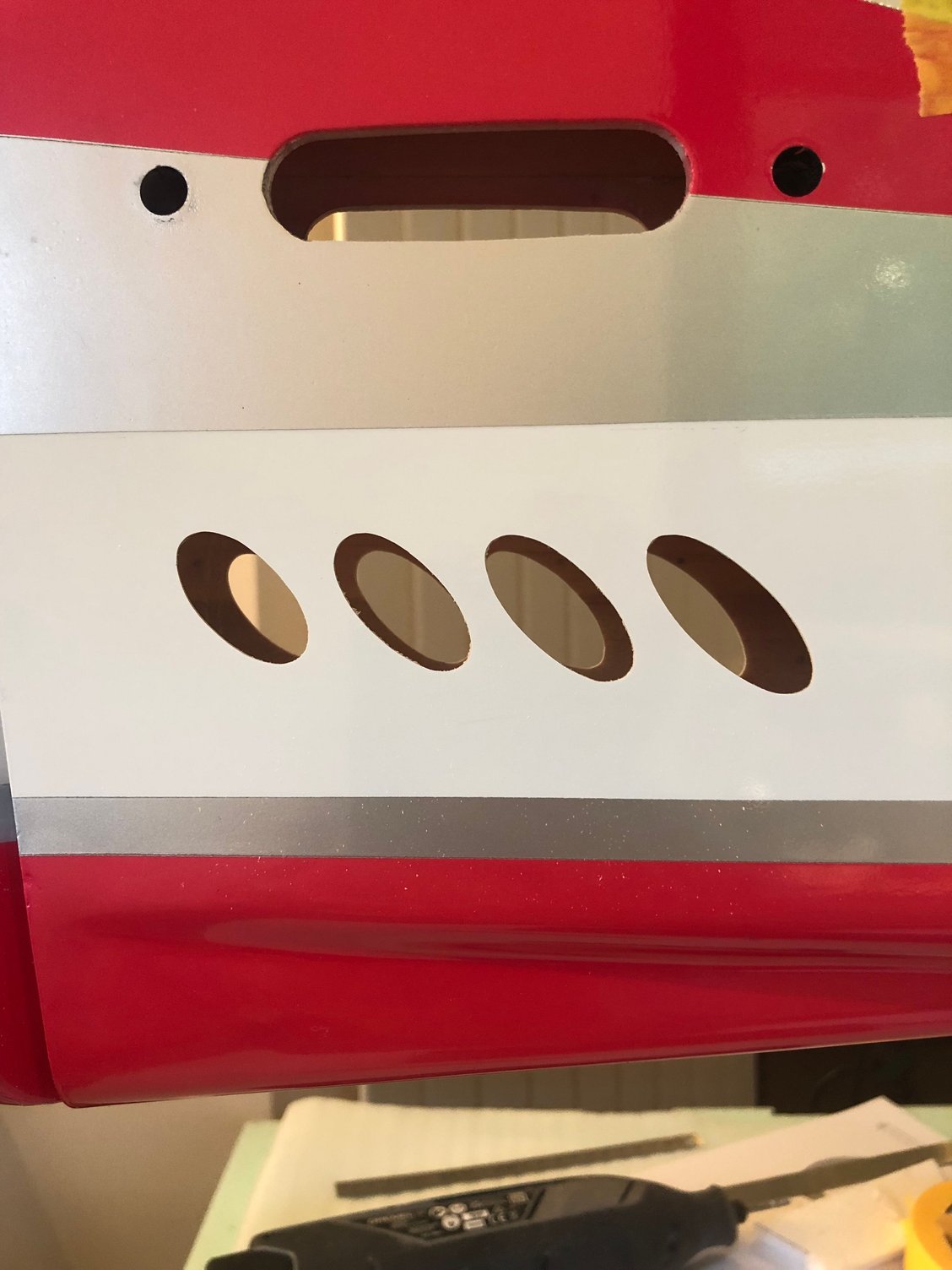
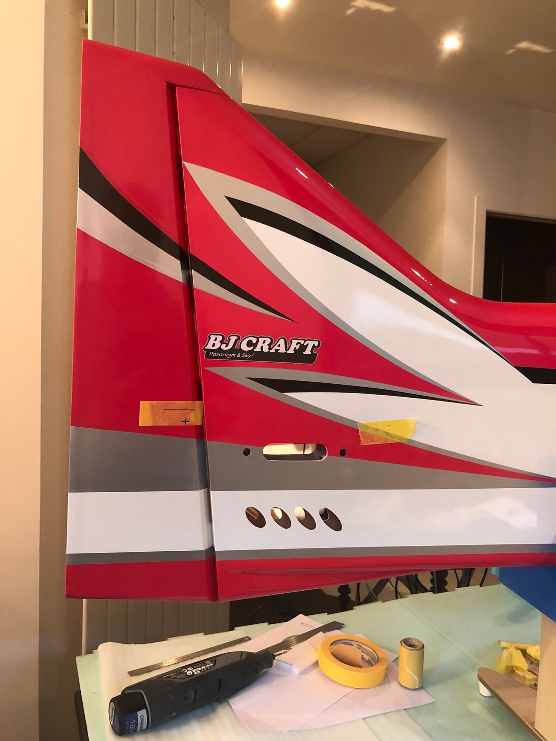
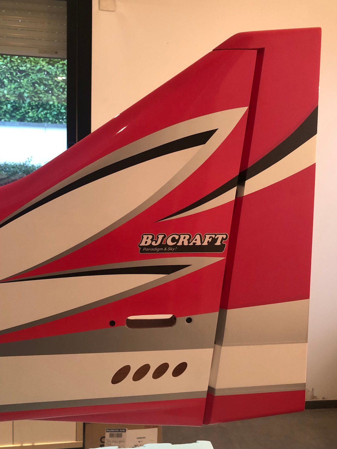
Right and left sides, bottom of fuselage from the nose ring to the landing gear box.
Then I worked on the air intake on the front part of the fuselage, and the air exit at the rear, in the tail post, that has been sufficient for an adequate ventilation until 30 C
With the D3 at 45 degrees in the air intake, temperatures of batteries on the Leader G with the same vents exits were not a concern
Maybe in hot countries an extra exit underneath the fuselage is necessary as done on Fujita model and recommended by BJ
I’ts why I add additional vent exits at the rear of the fuselage …. more sexy than the holes in the bottom of the fuselage 😀
The question is how much is the increase in weight with the glass cloth reinforcement ?
+ 14 g / 1/2 ounce after the ventilation done compare to the initial weight.
The following users liked this post:
wattsup (02-12-2025)
02-13-2025 | 10:32 AM
#12
Thread Starter
My Feedback: (1)
Landing gear box reinforcement
For flights from a concrete runway, there is nothing to do, except eventually use some thin CA
Flying from a narrow runway where excursions are common during landing in crosswind conditions or from grass runway, I have been doing with success this kind of reinforcement starting with the IMMORTAl, SP PASSION, EPILOGUE and the LEADER G.
Carbon braid with resin for the formers, carbon plate 1 & 1,5 mm with epoxy both sides of the ldg box
Total increase of weight of the fuselage with previous fuselage reinforcement 44 g less than 2 ounces
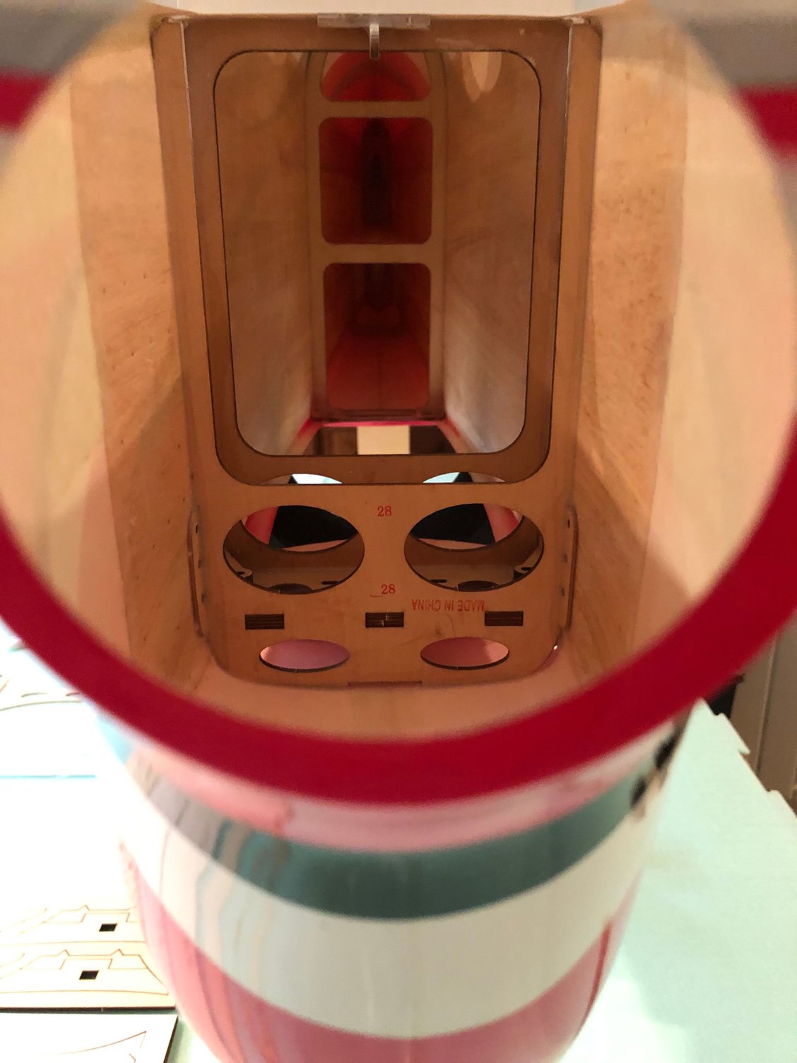
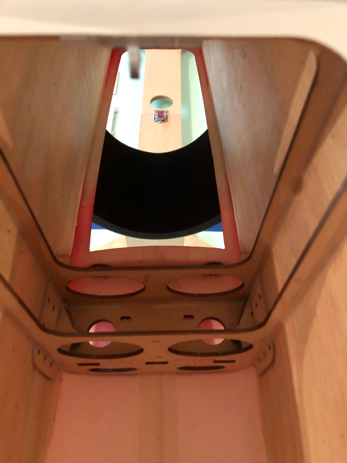
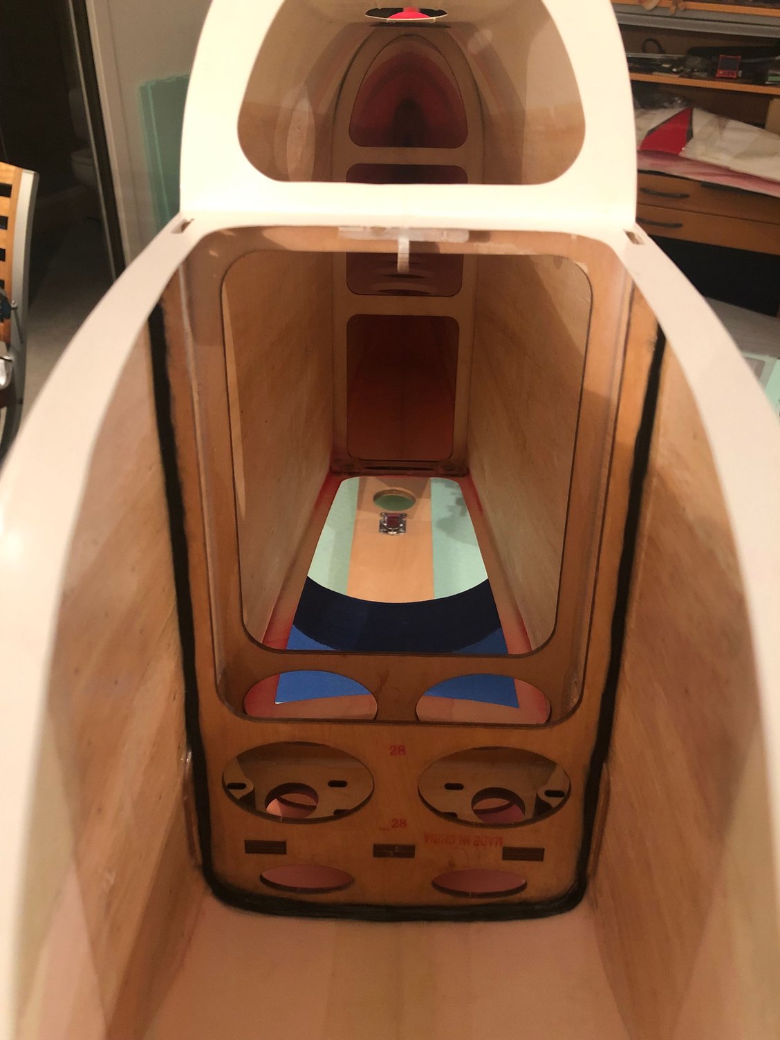
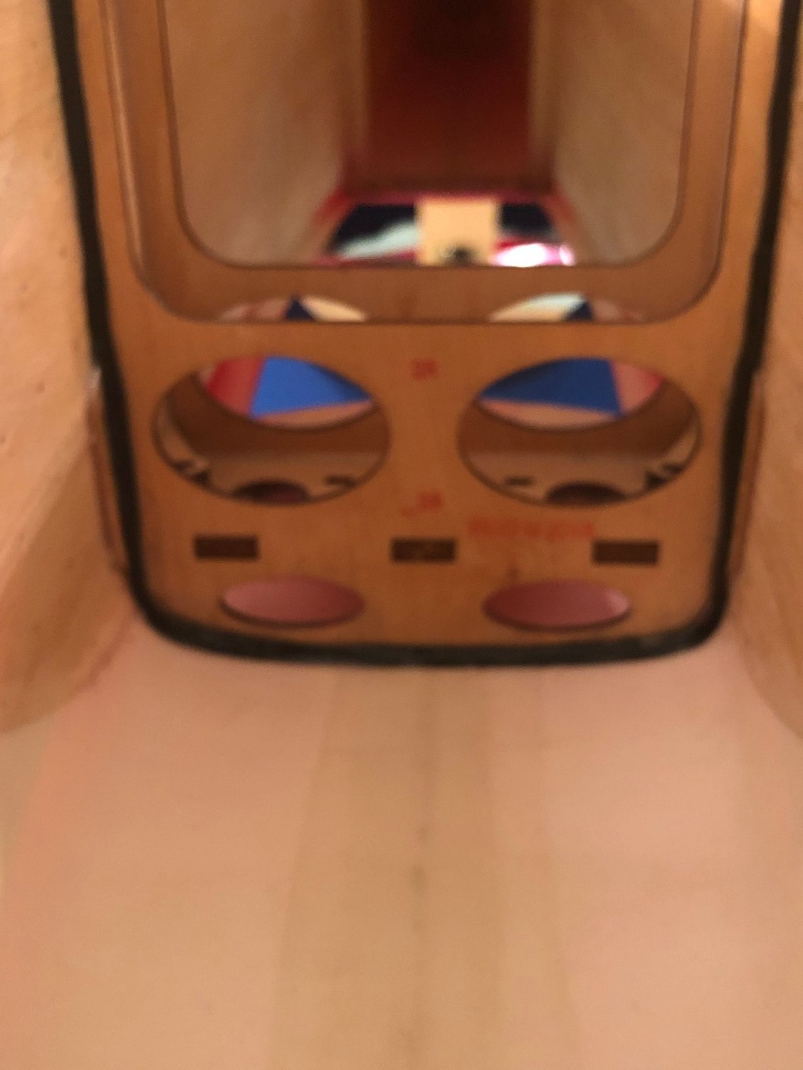
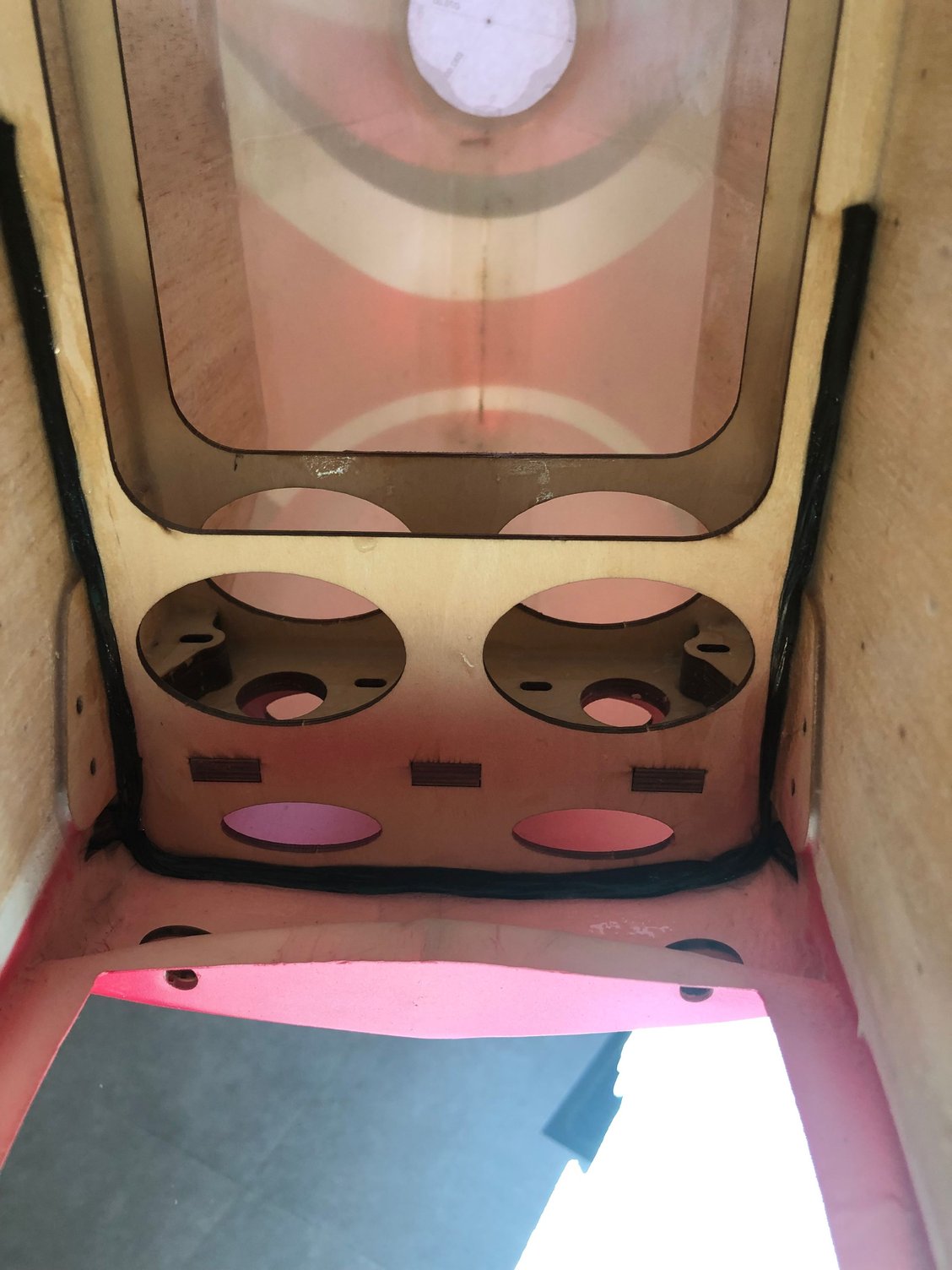
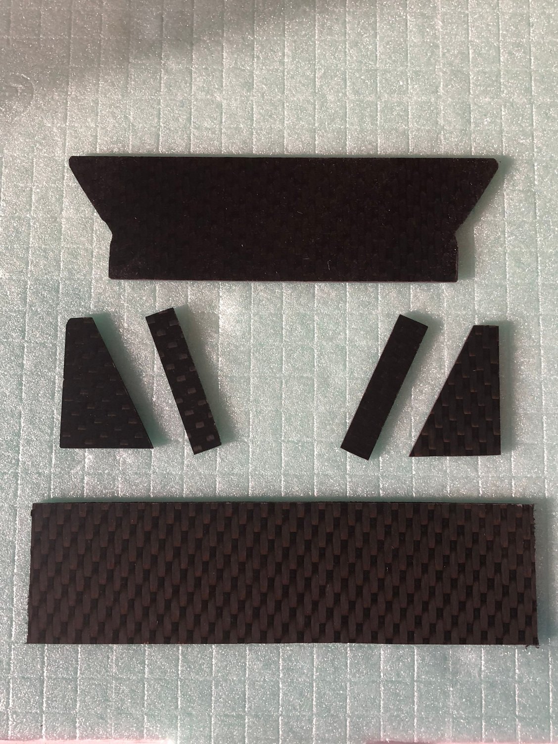

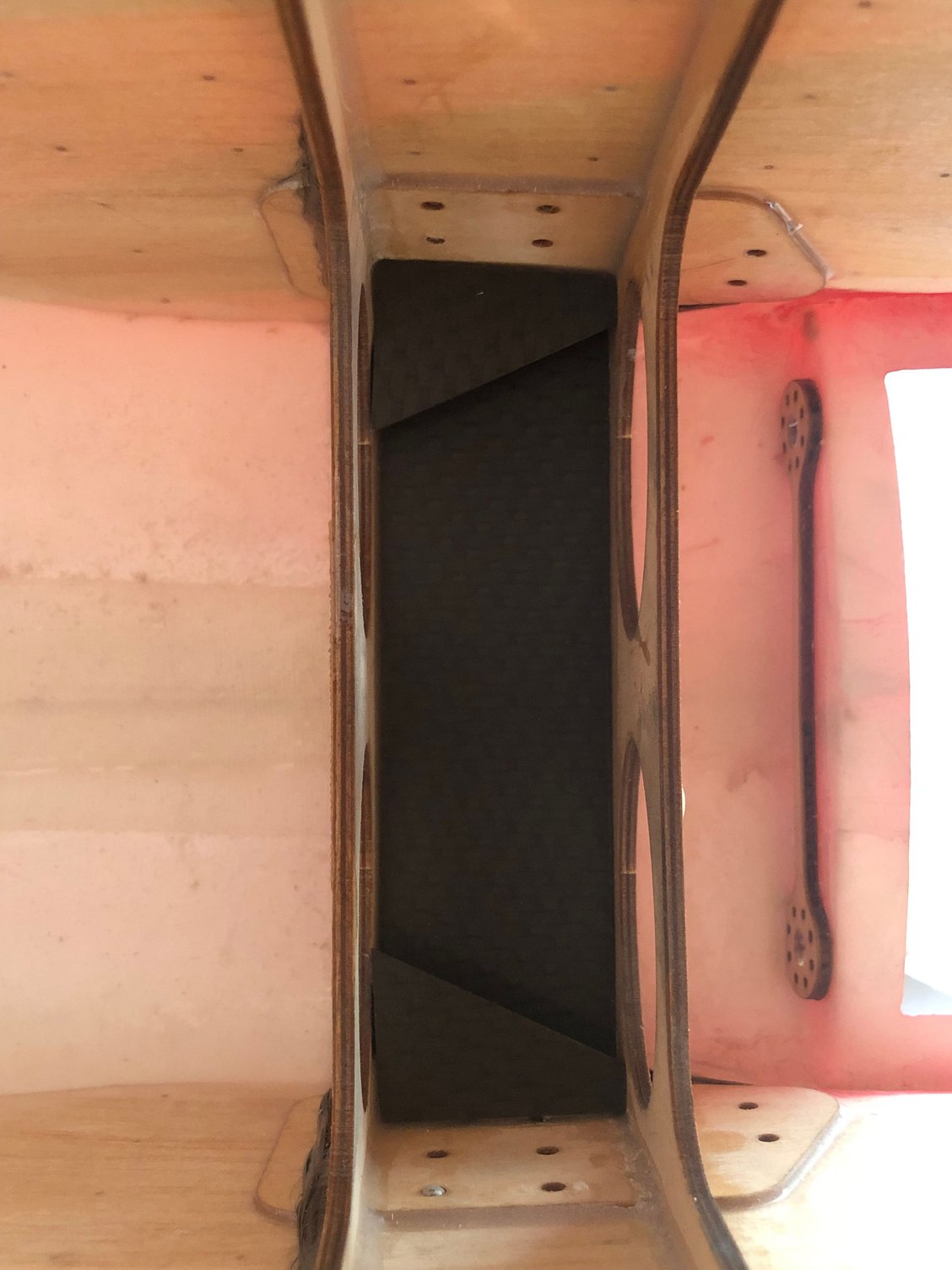
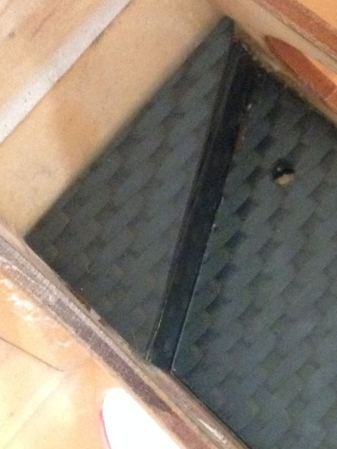
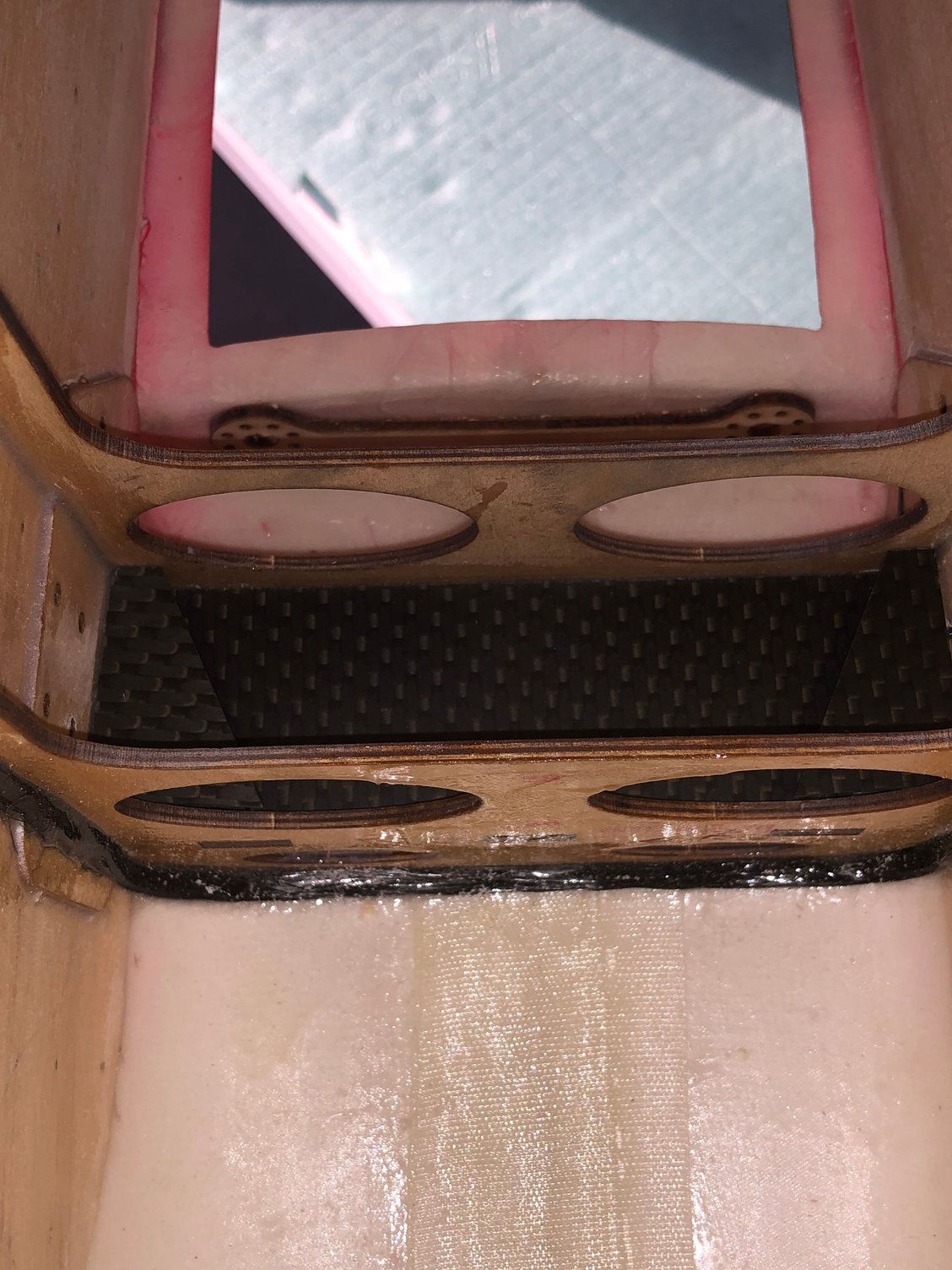
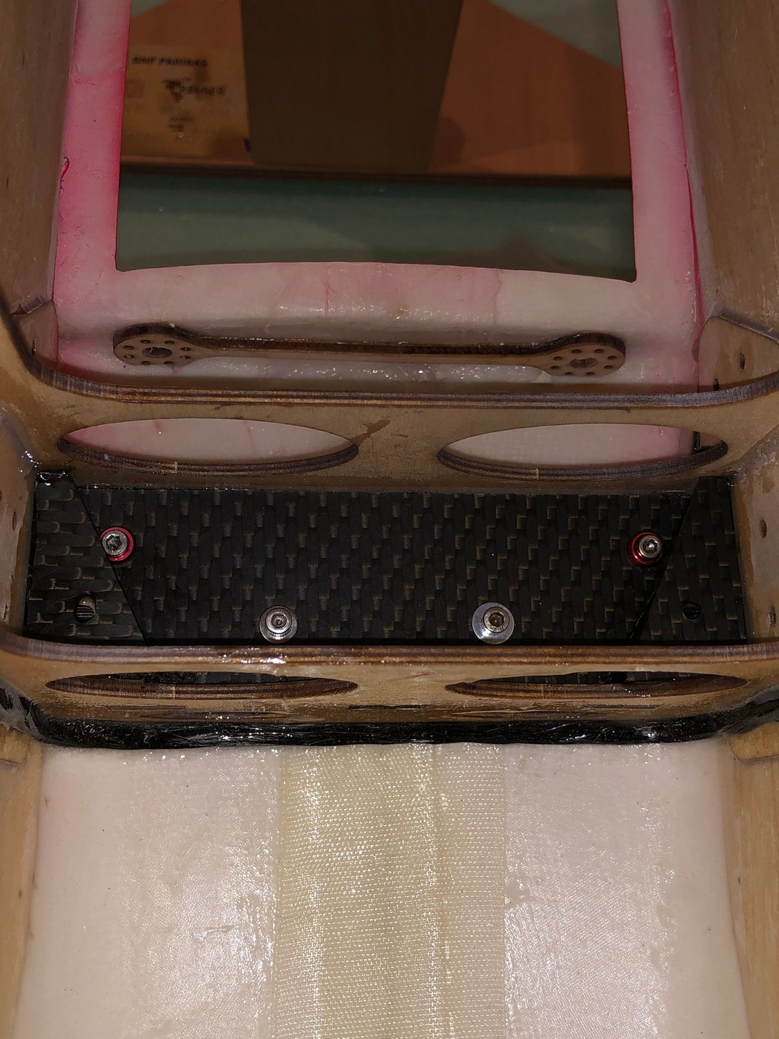
For flights from a concrete runway, there is nothing to do, except eventually use some thin CA
Flying from a narrow runway where excursions are common during landing in crosswind conditions or from grass runway, I have been doing with success this kind of reinforcement starting with the IMMORTAl, SP PASSION, EPILOGUE and the LEADER G.
Carbon braid with resin for the formers, carbon plate 1 & 1,5 mm with epoxy both sides of the ldg box
Total increase of weight of the fuselage with previous fuselage reinforcement 44 g less than 2 ounces
The following users liked this post:
wattsup (03-30-2025)
02-19-2025 | 07:36 AM
#13
Thread Starter
My Feedback: (1)
Rudder installation
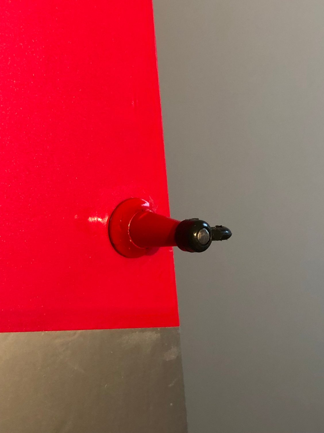
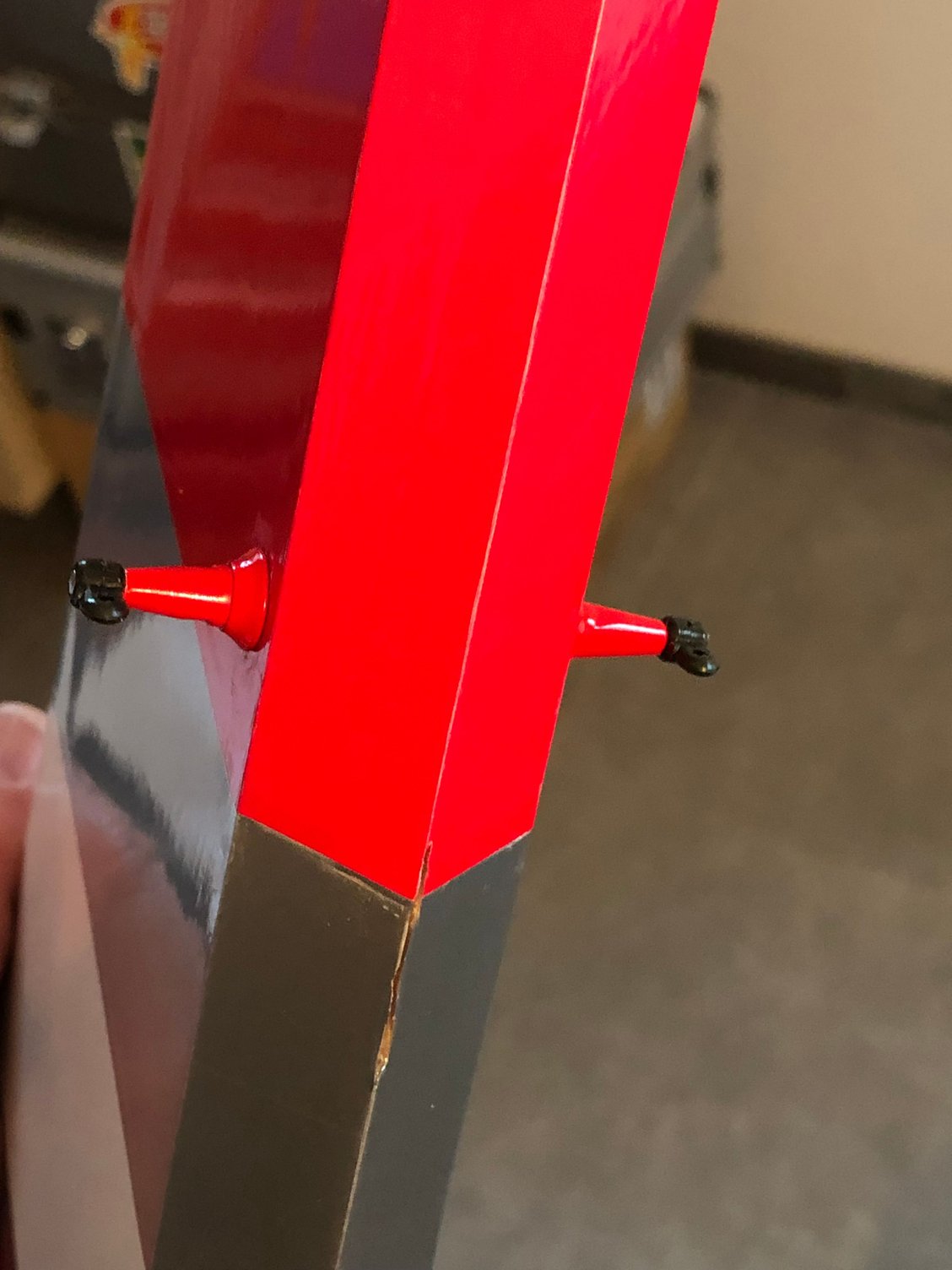
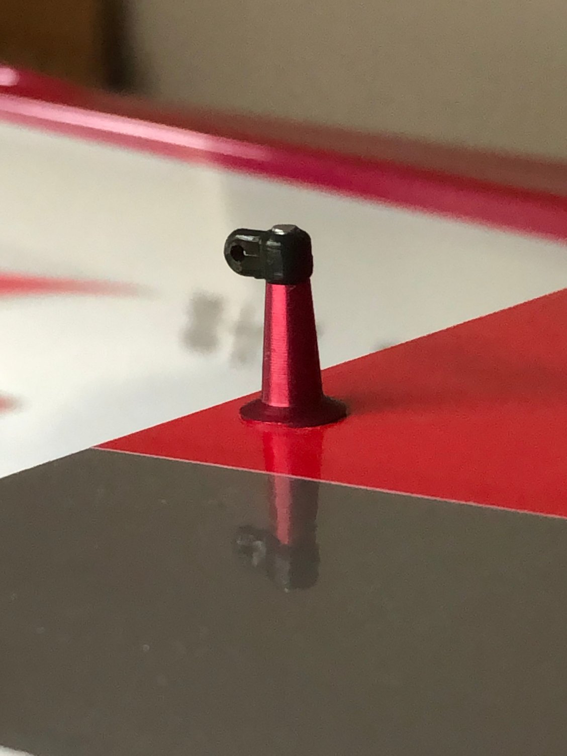
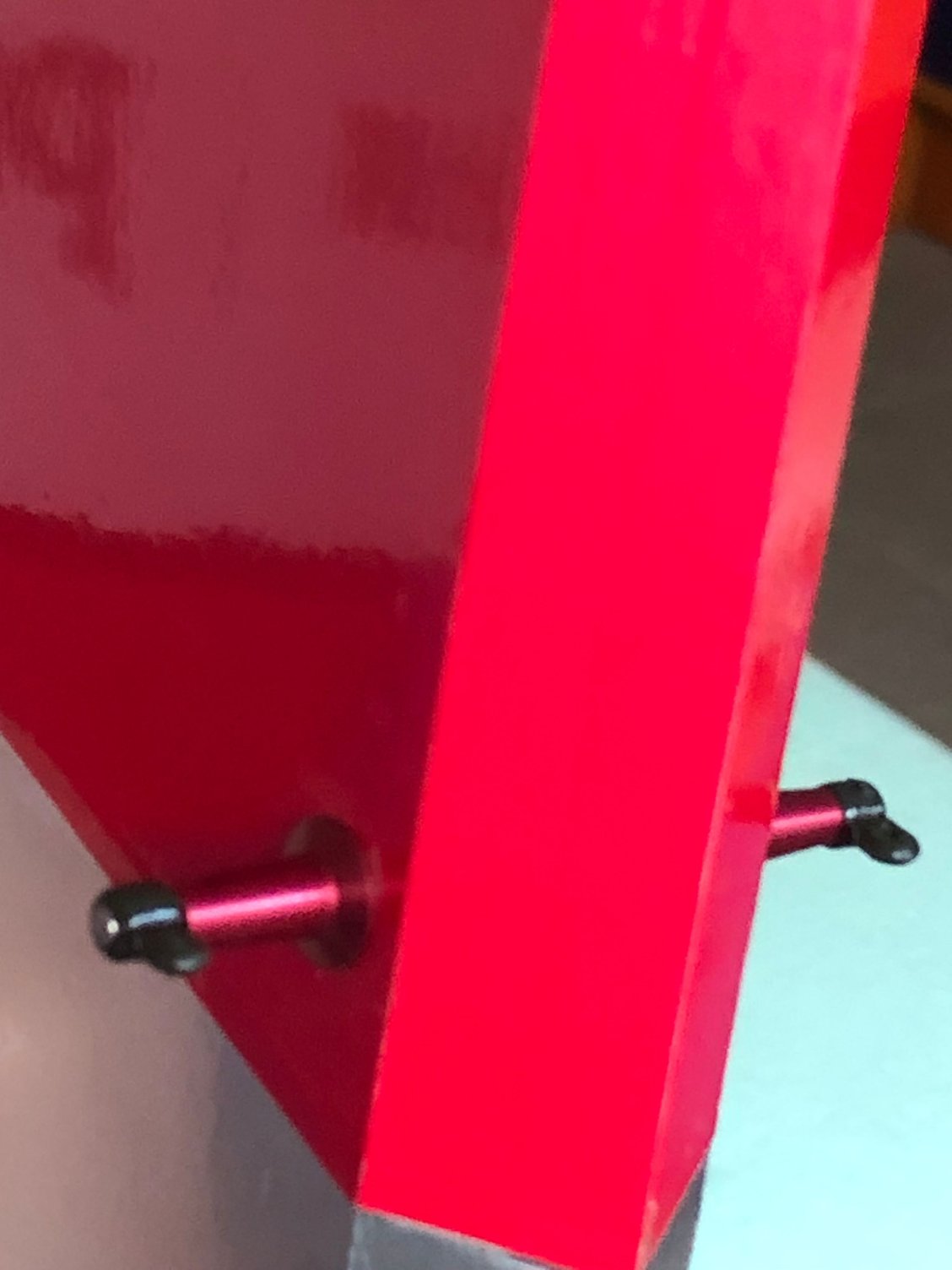
I use 5 of the Radio South 1/4 scale Pro Hinges glued with thin CA
For the horn, I prefer the GO model device to the supplied one
I drill a 8 mm hole in the rudder to glue with epoxy around piece of hard wood
There is a 25mm x 100mm hard balsa at this location according BJ
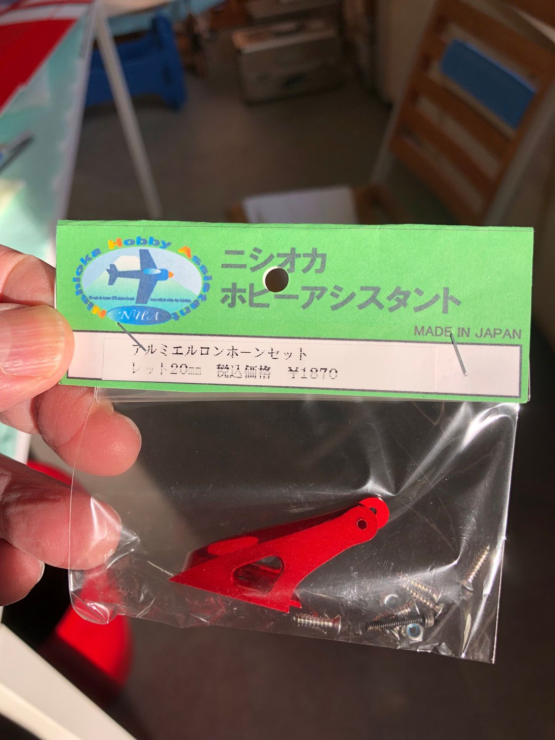
Tried to paint the parts to match the rudder color, but ended with aluminium Nishioka parts I had in stock.
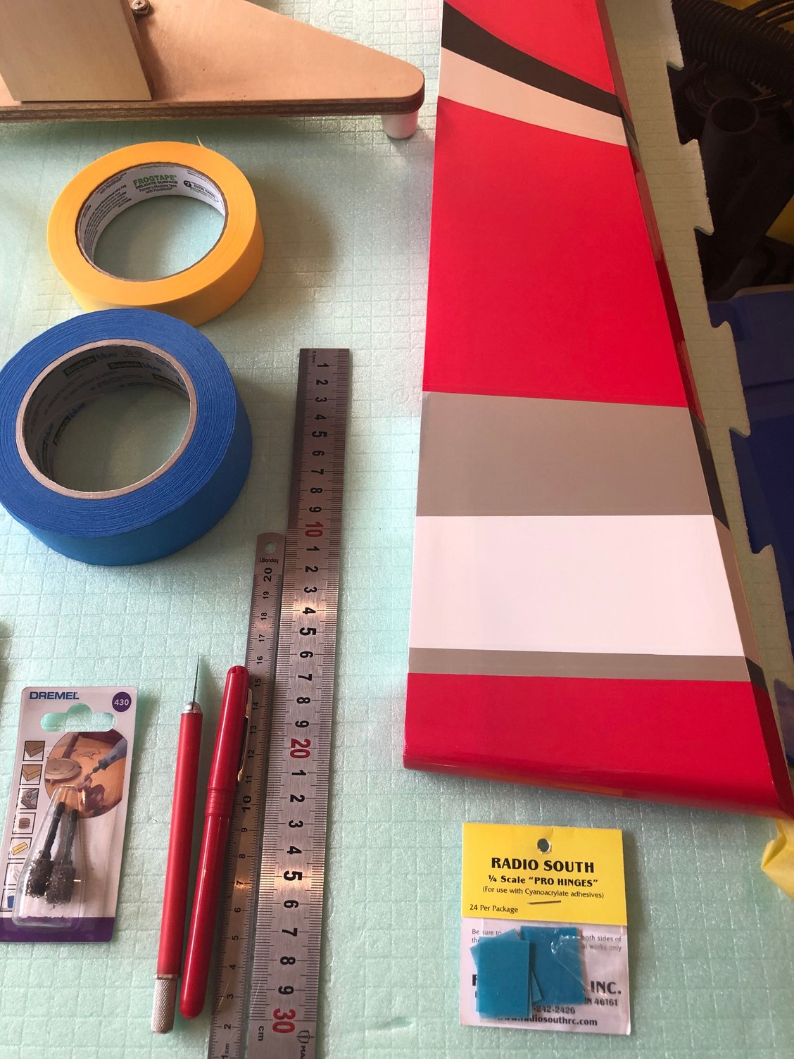
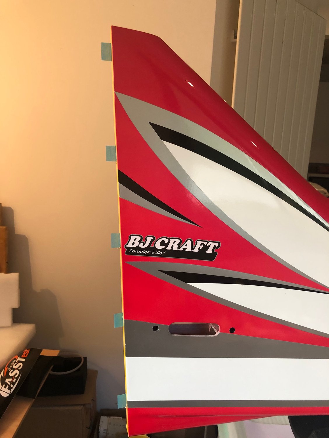
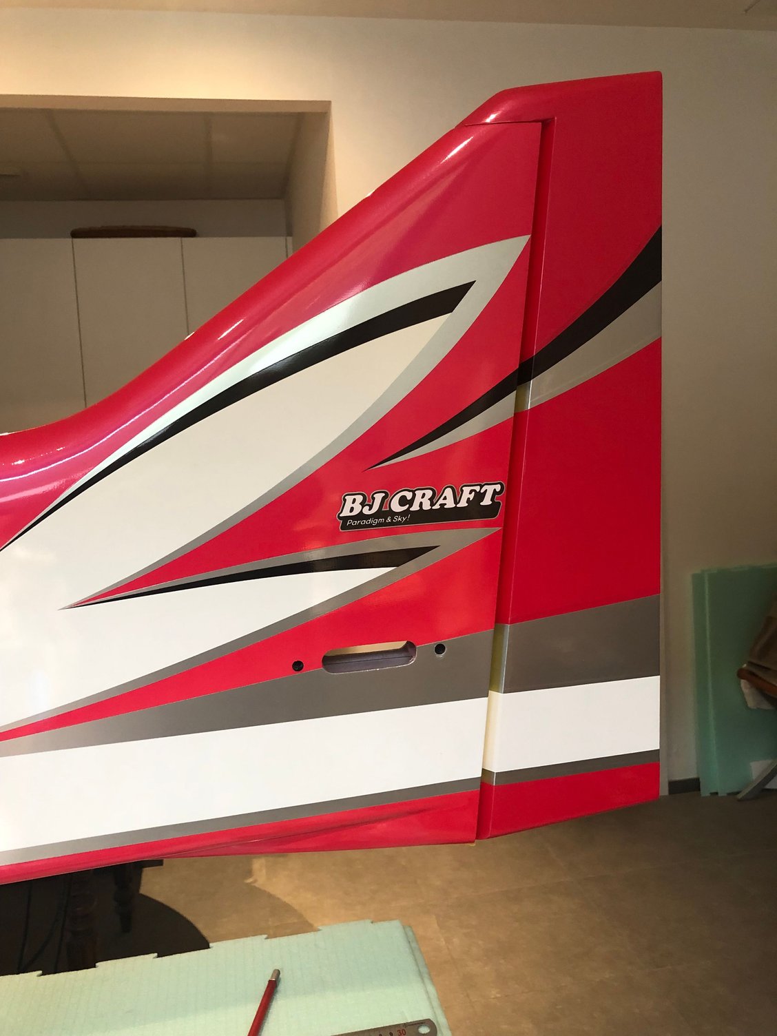
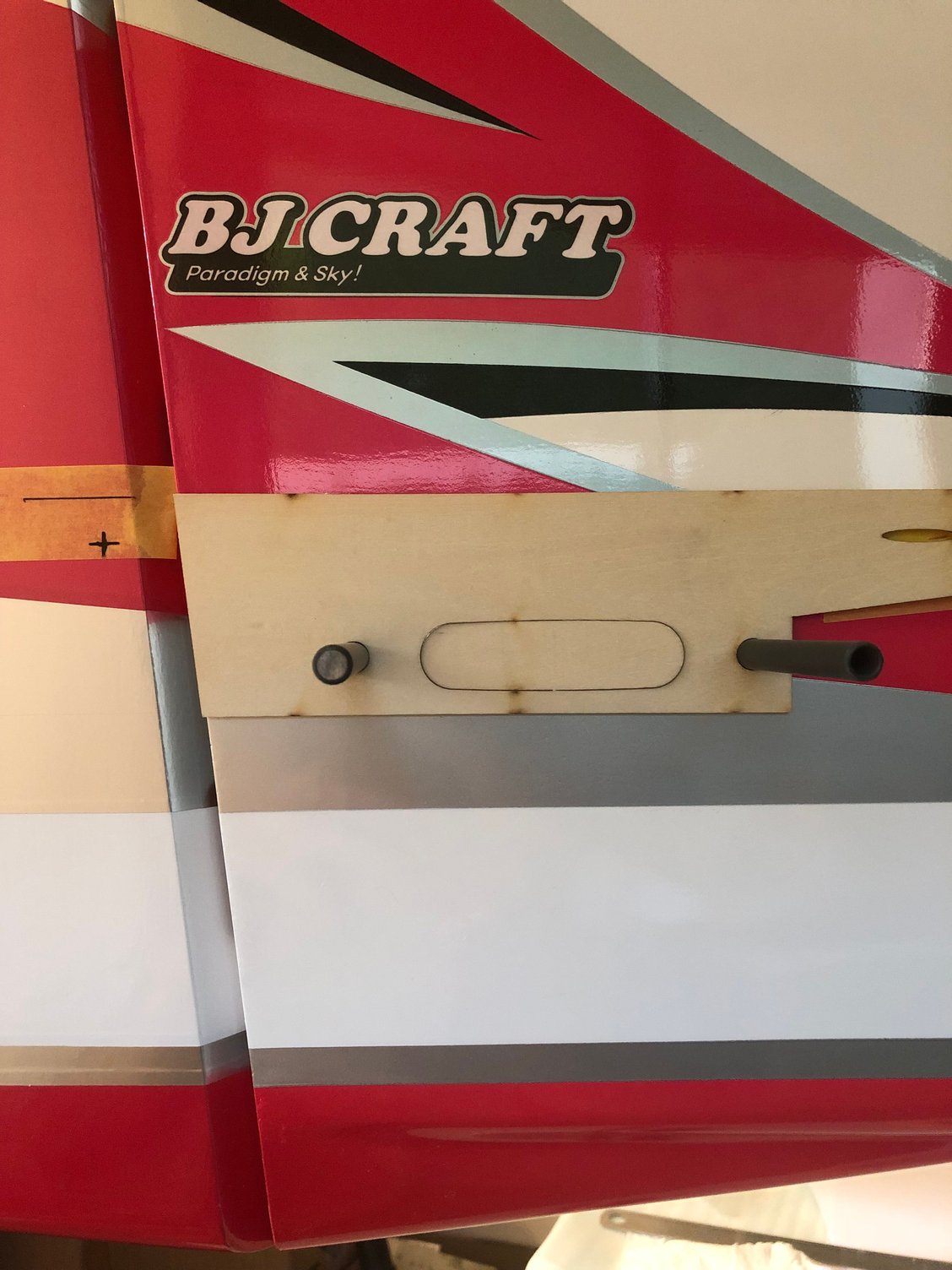
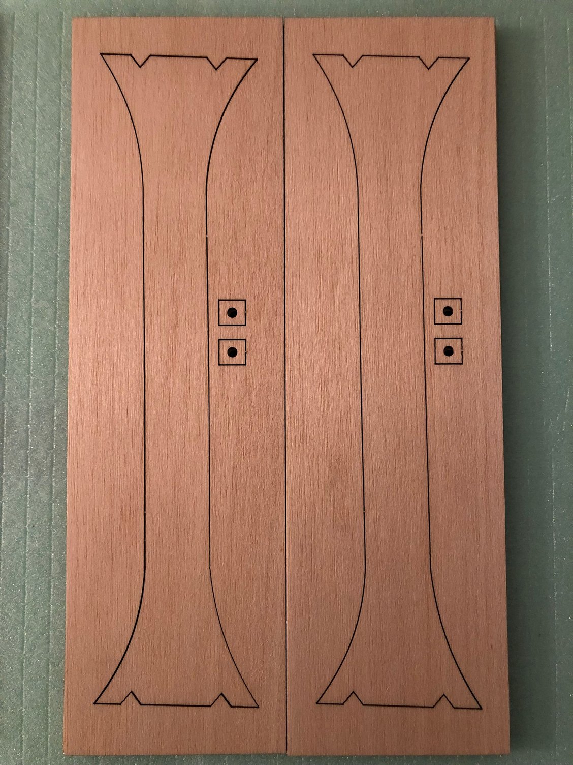
This template give the right position for the rudder horn
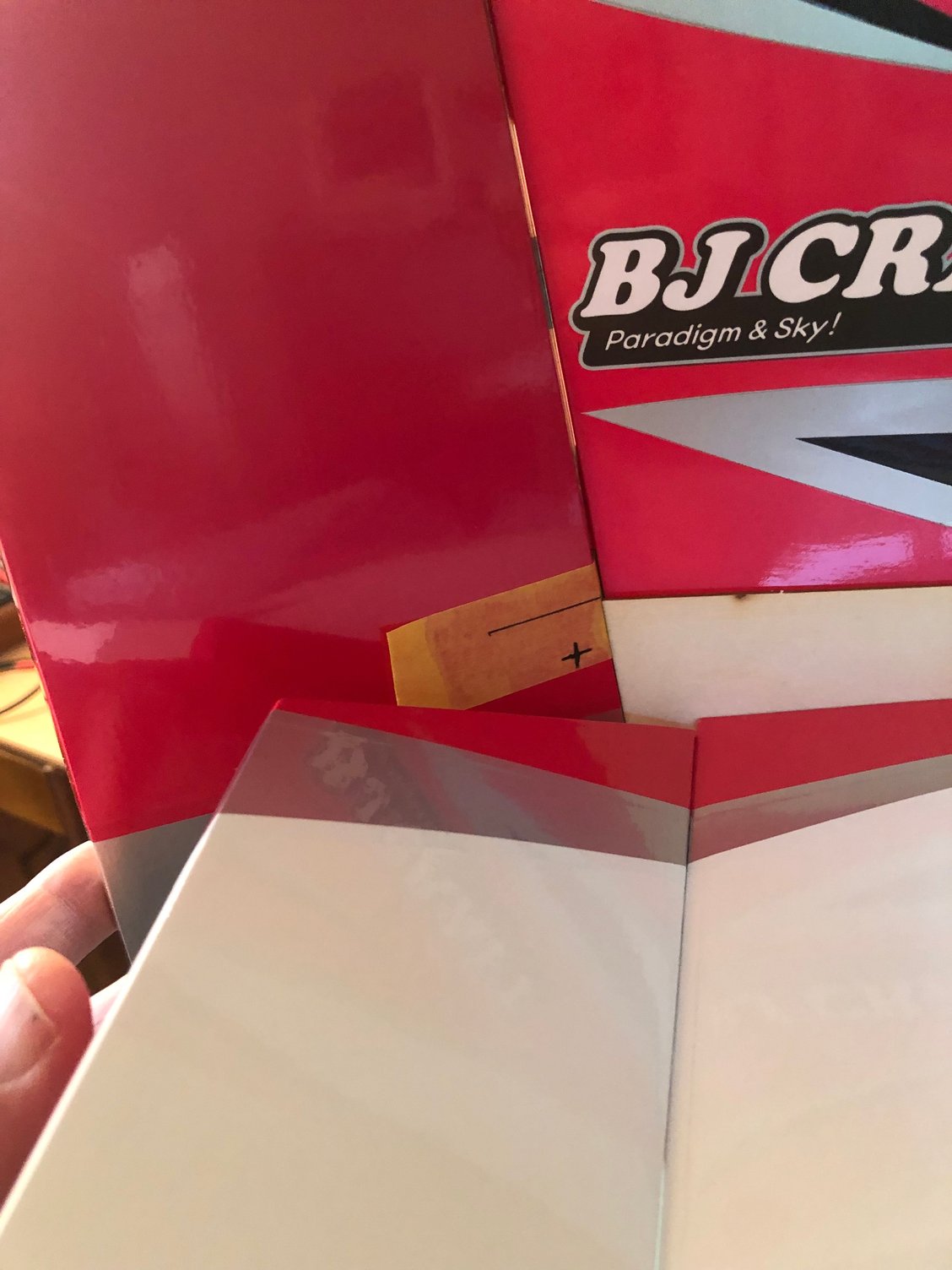
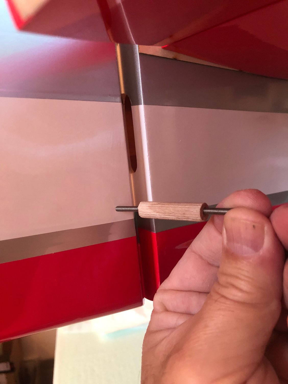
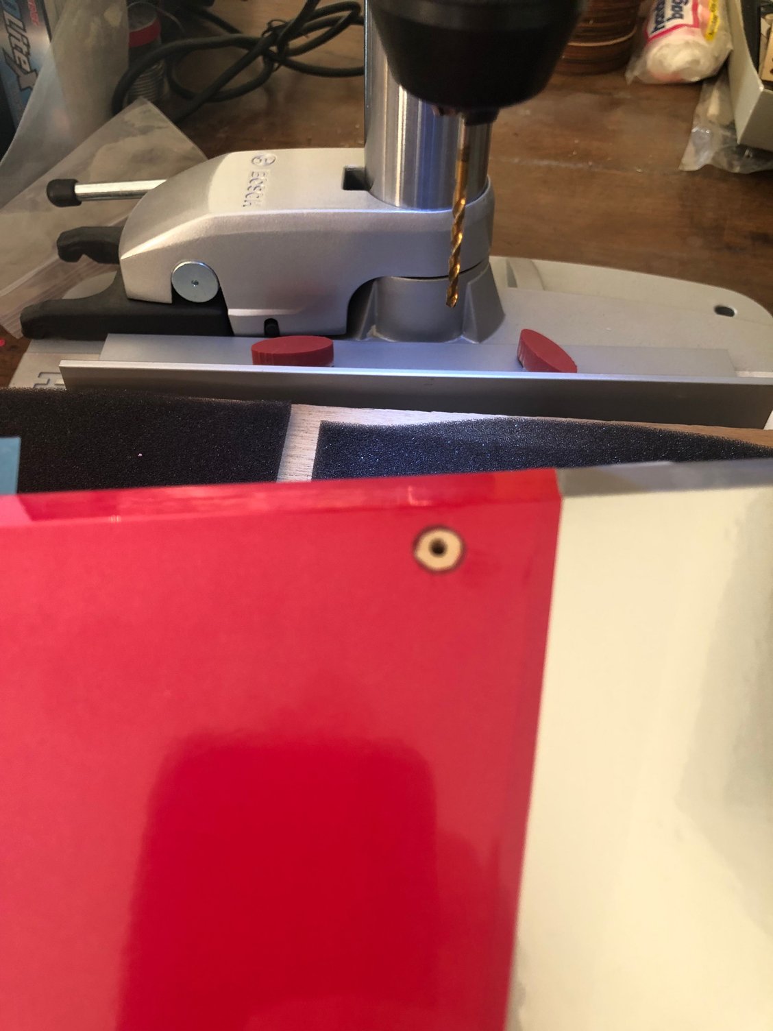
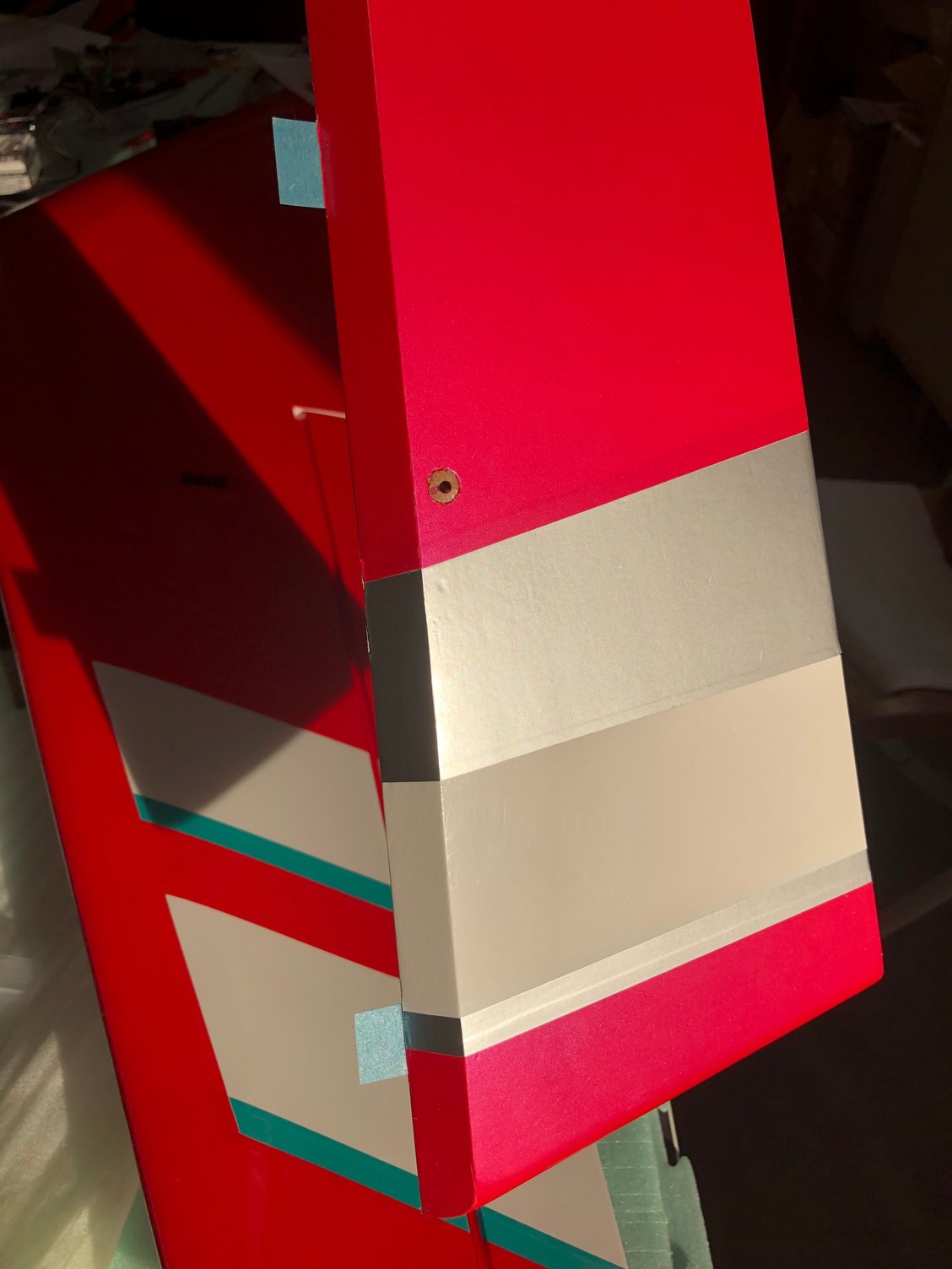
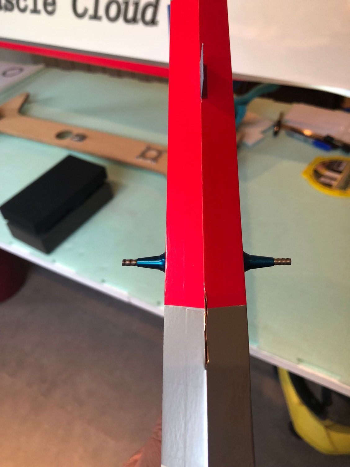
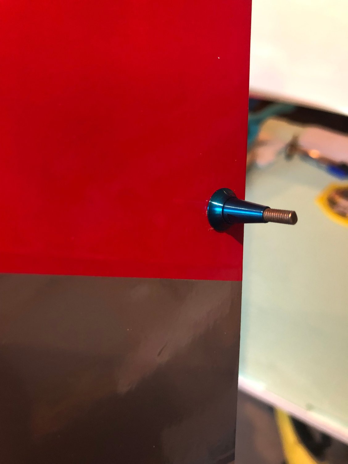
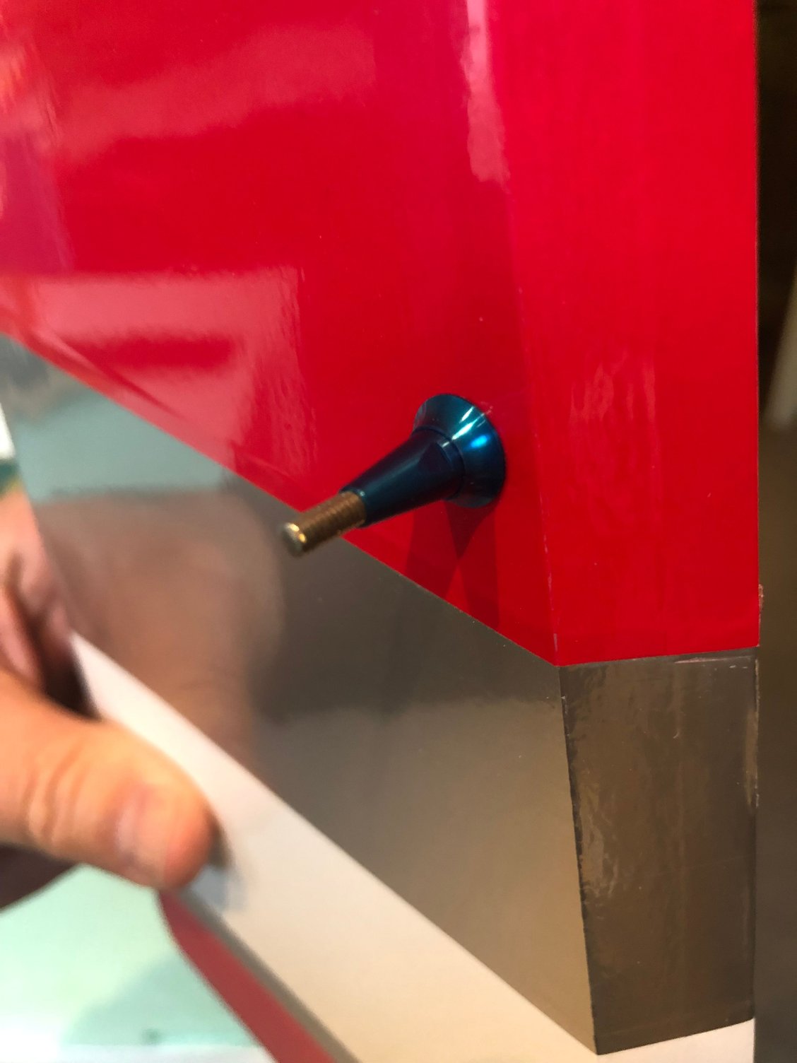
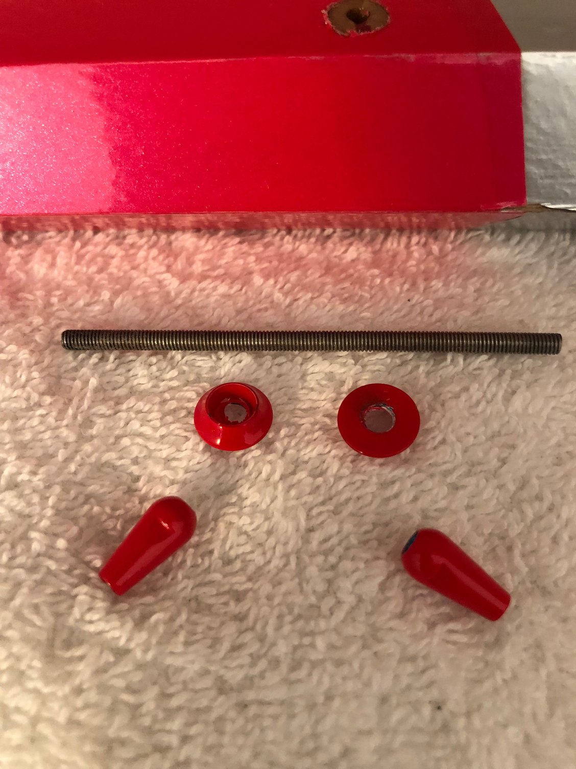
I use 5 of the Radio South 1/4 scale Pro Hinges glued with thin CA
For the horn, I prefer the GO model device to the supplied one
I drill a 8 mm hole in the rudder to glue with epoxy around piece of hard wood
There is a 25mm x 100mm hard balsa at this location according BJ
Tried to paint the parts to match the rudder color, but ended with aluminium Nishioka parts I had in stock.
This template give the right position for the rudder horn
The following 2 users liked this post by J-P:
rcprecision (02-19-2025),
wattsup (02-19-2025)
02-21-2025 | 10:59 AM
#14
Thread Starter
My Feedback: (1)
Stabilizer and Elevators
Hinges are glued in place with thin CA
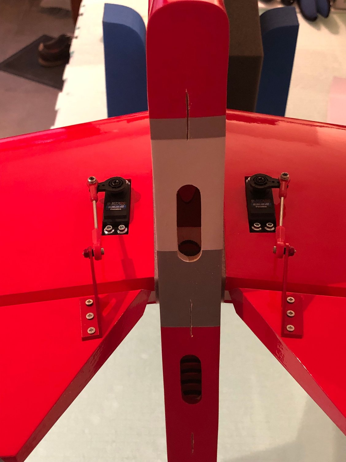
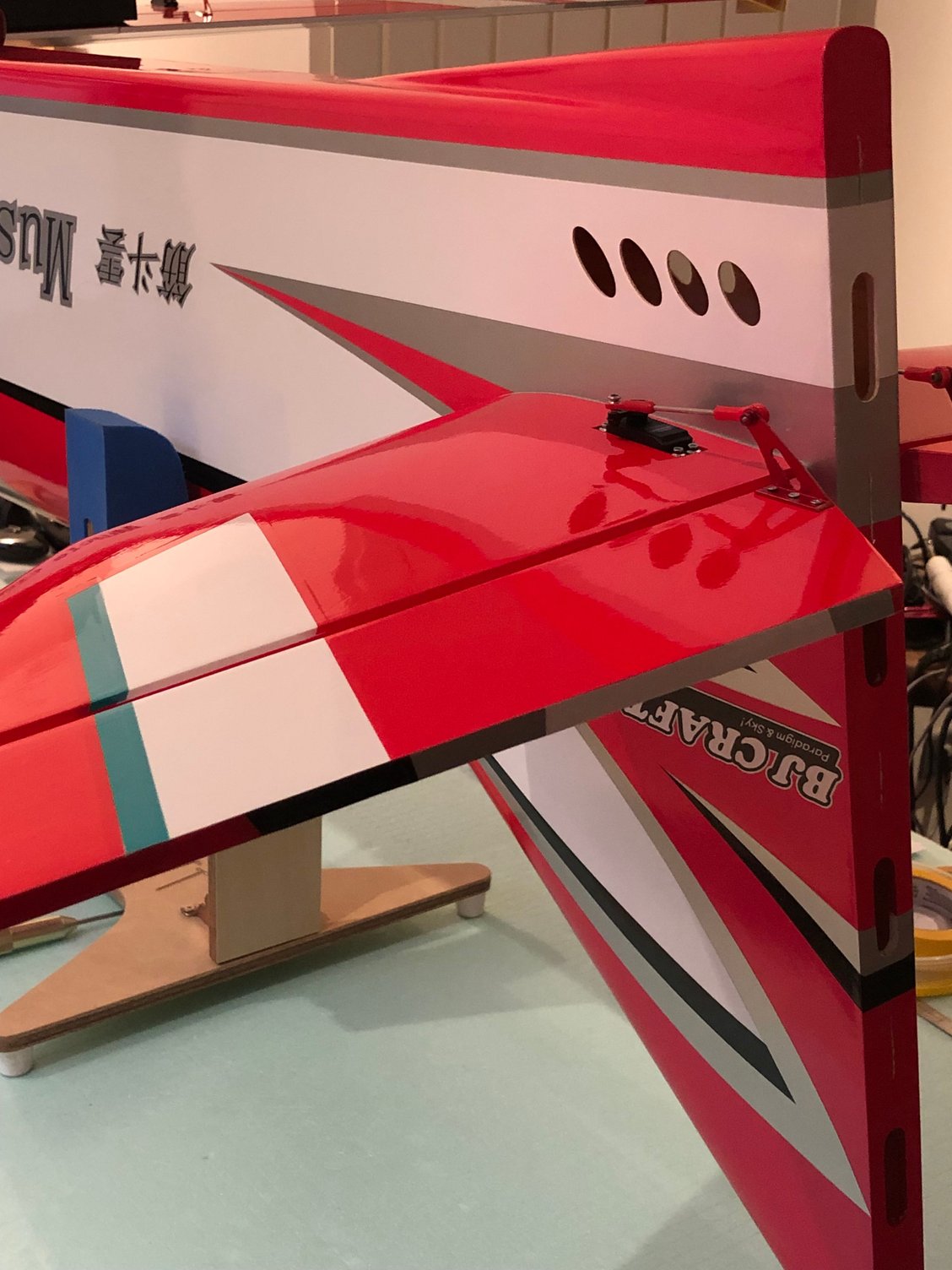
I used two FUTABA BLS 173 SVI for the elevators and NISHIOKA control horns instead of the ones included in the kit
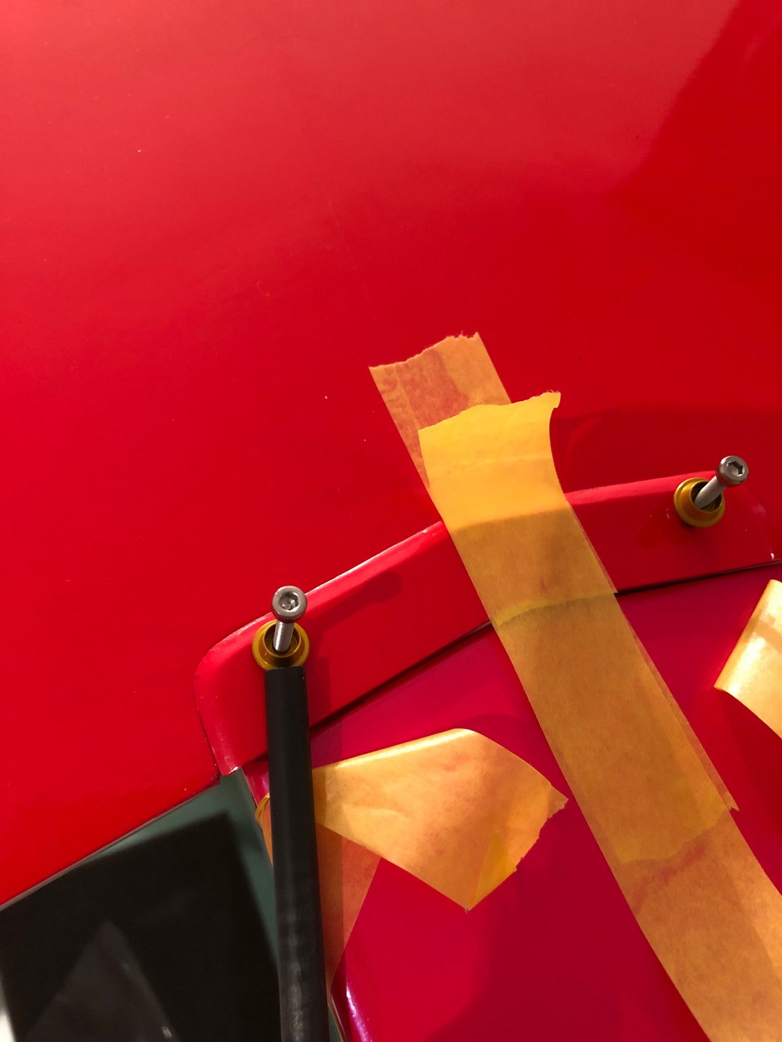
After positioning them and drilling the holes for the screws, I remove some covering material and use a pin before dropping some thin CA to reinforce the balsa.
I proceeded like this for all my planes and had no issue ….. until now
I use the standard Futaba horns and choice the arm the most parallel to the moving surface leading edge, then adjust with the SBUS, not the sub trim
Ball link and old red KATO ball bearings for the commands.
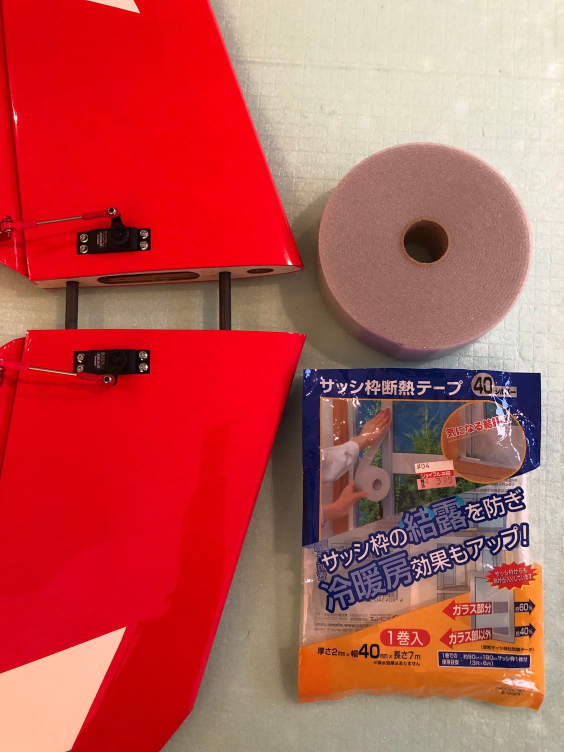
I ended up with this sticking foam I purchased in a Japanese store when shopping with GIICHI NARUKE and KEN HIROSE a few years ago . RIP NARUKE San.
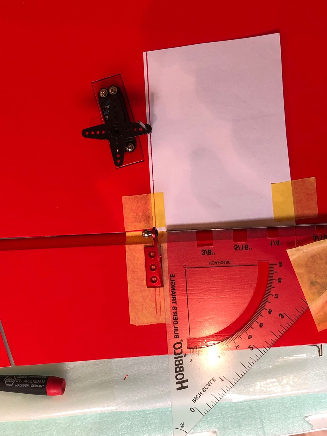
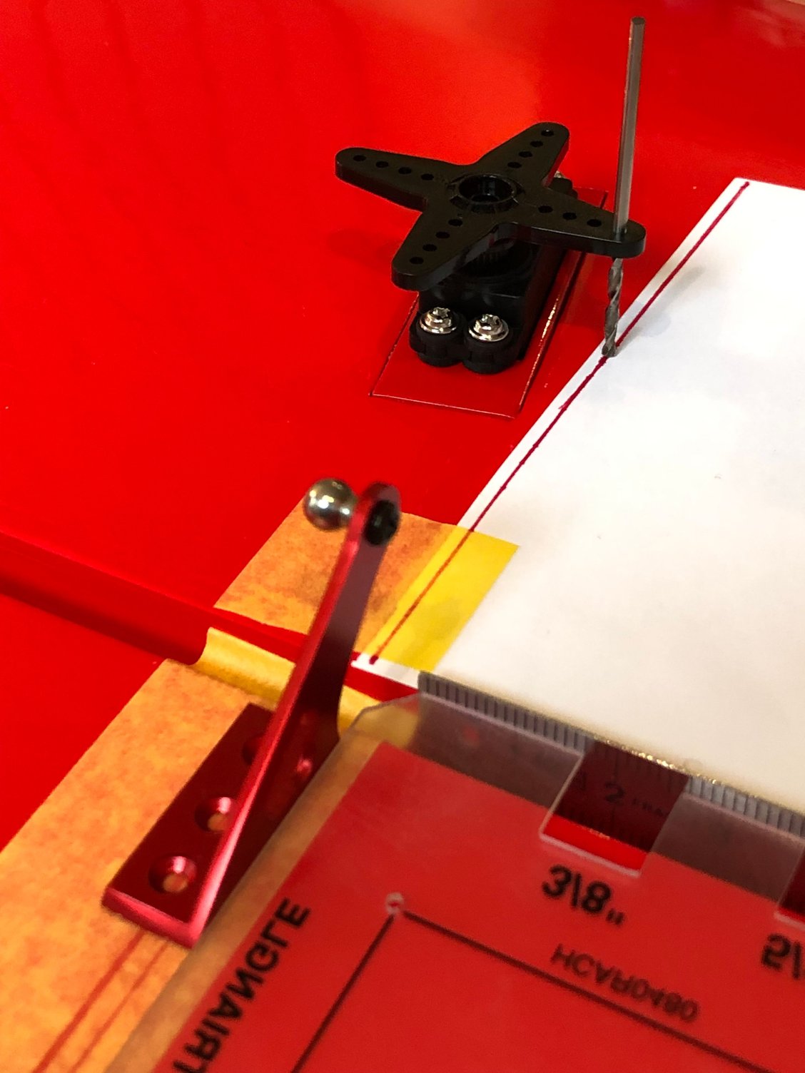
I add a series of pictures of one of my LEADER G stab showing how to position the control horn with precision.
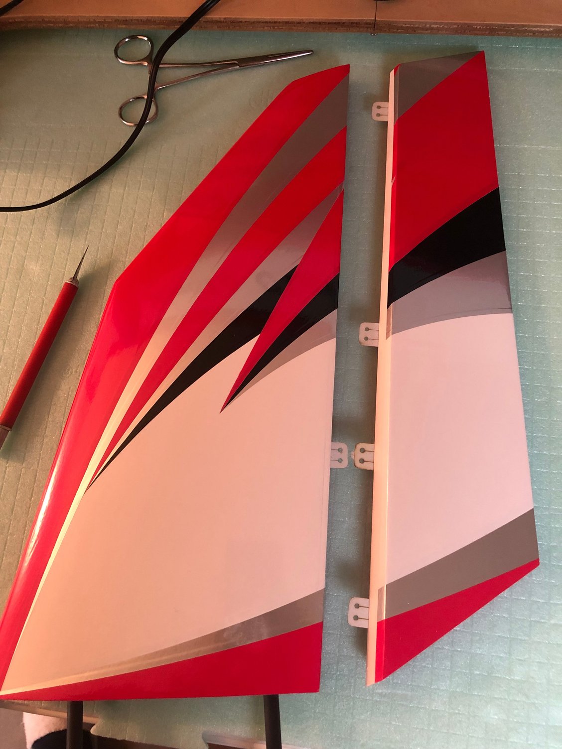
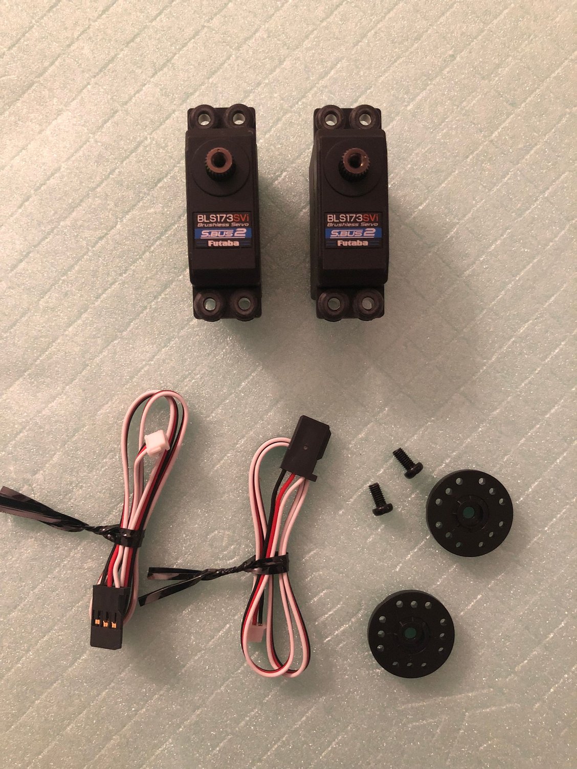
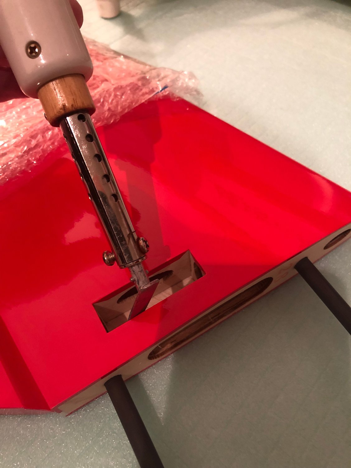
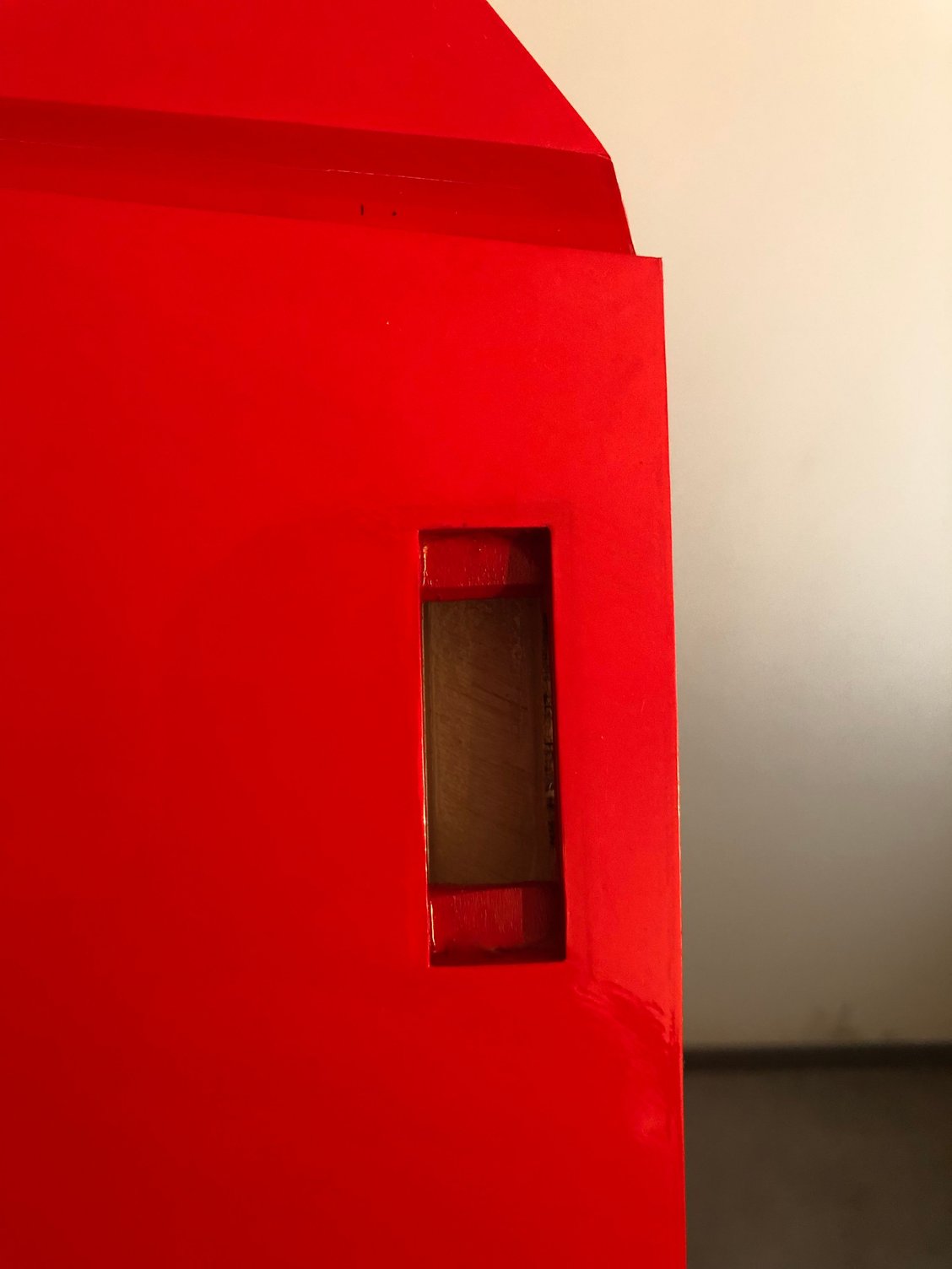
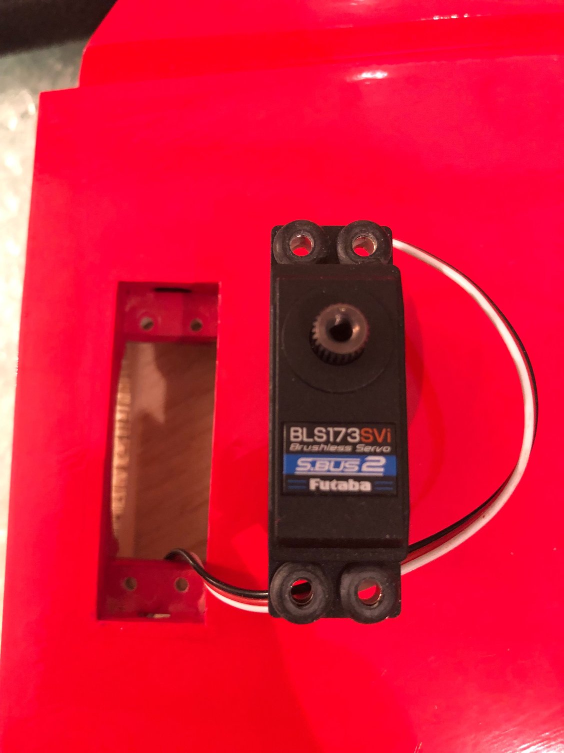
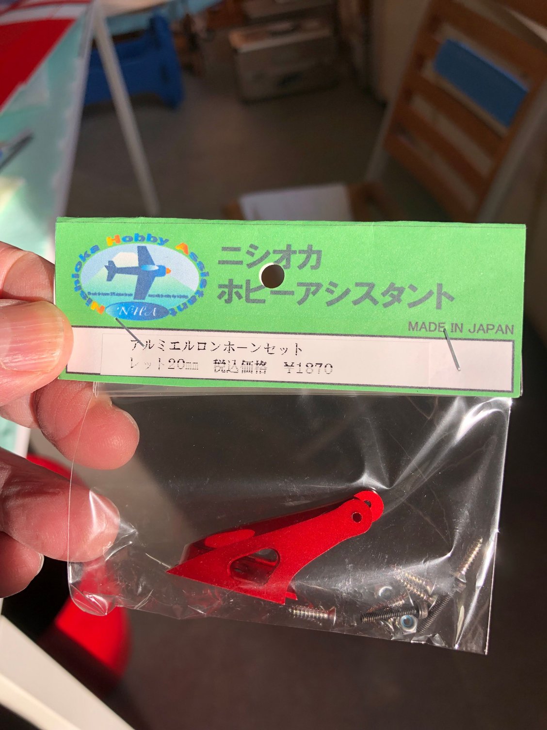
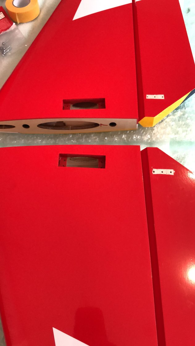
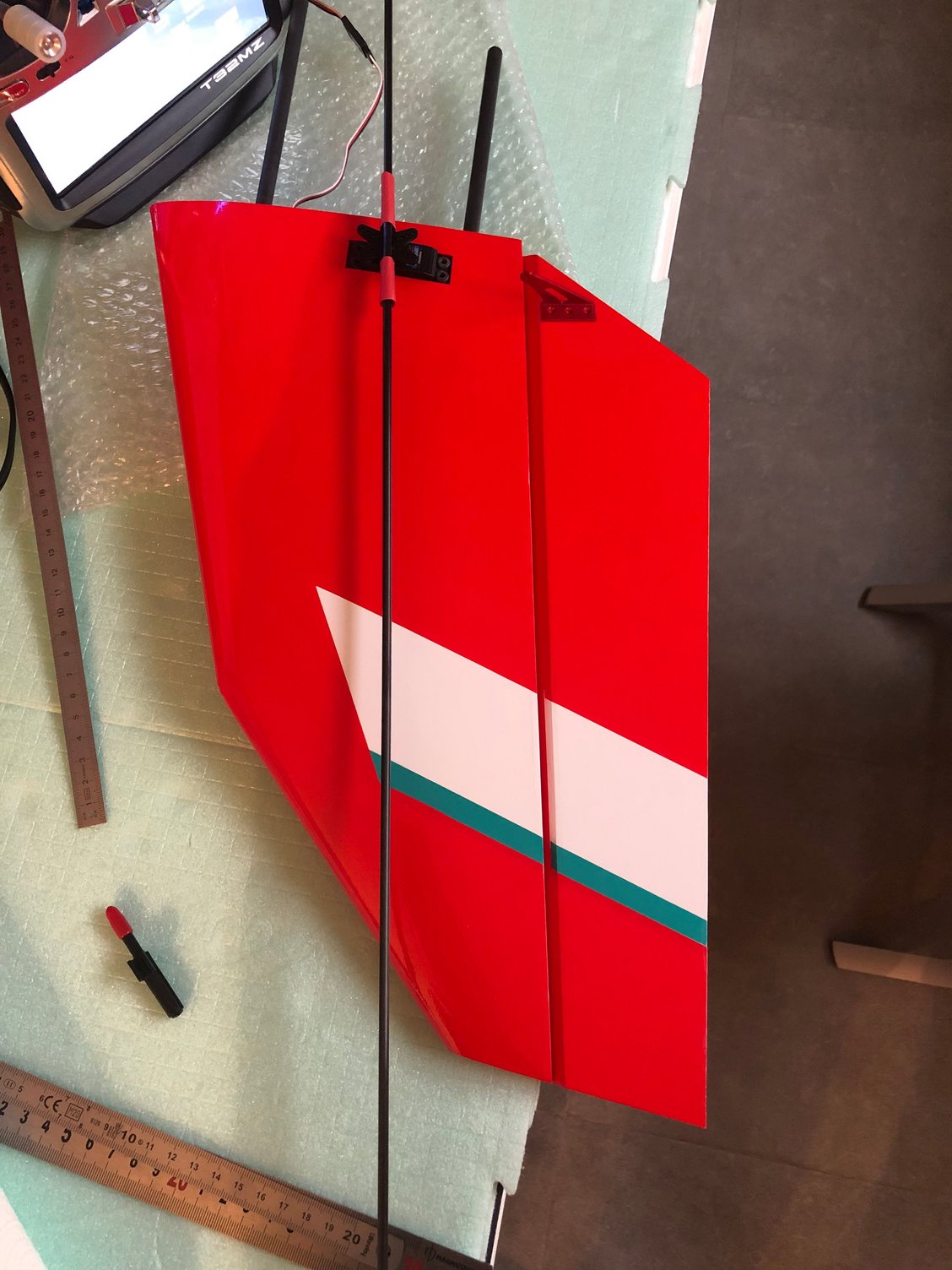
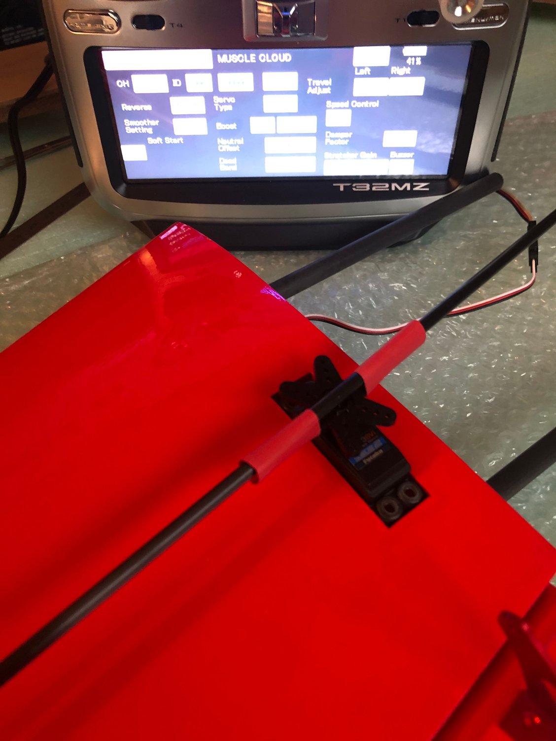
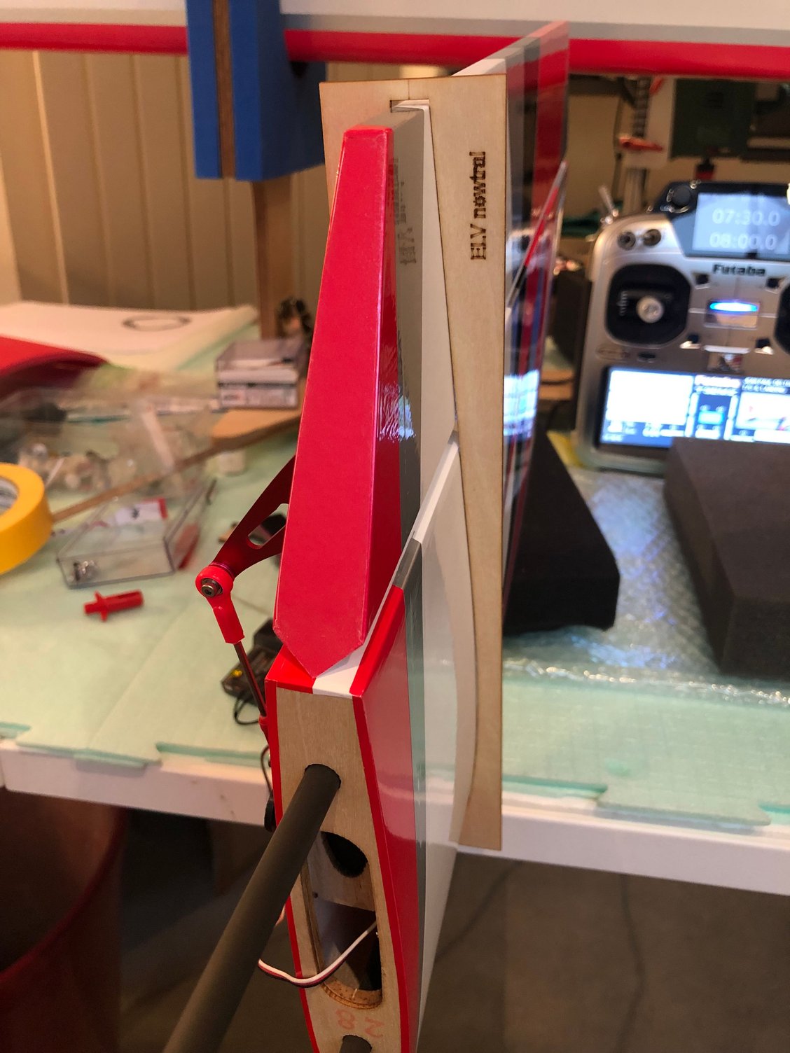

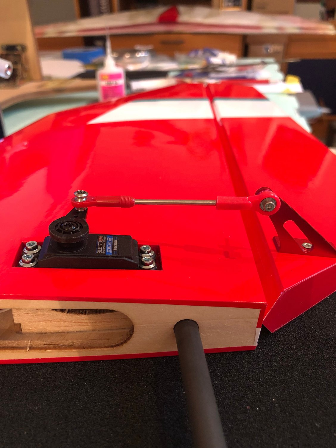
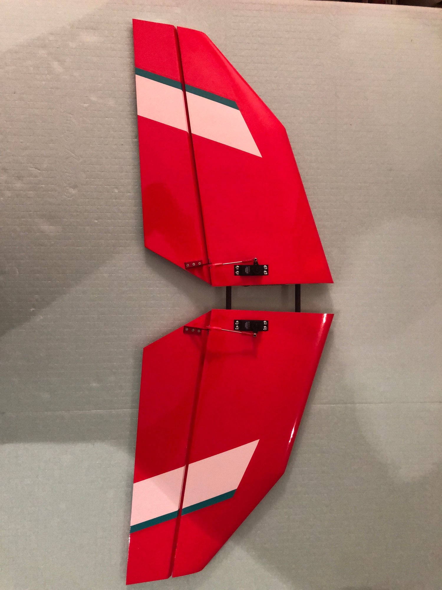
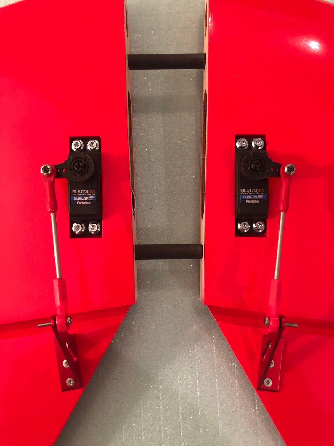
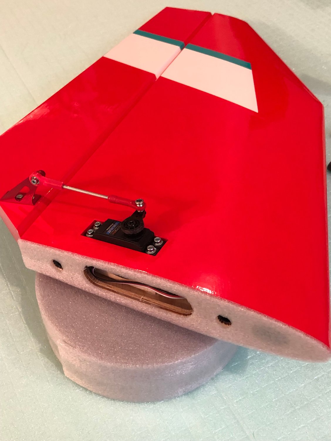
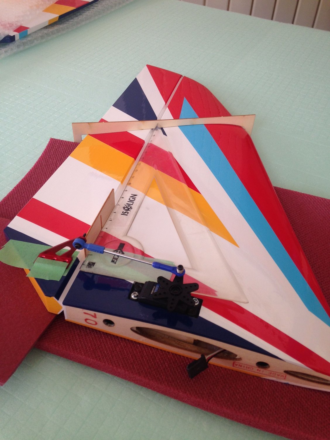
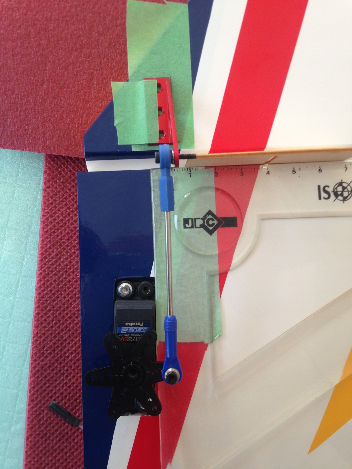
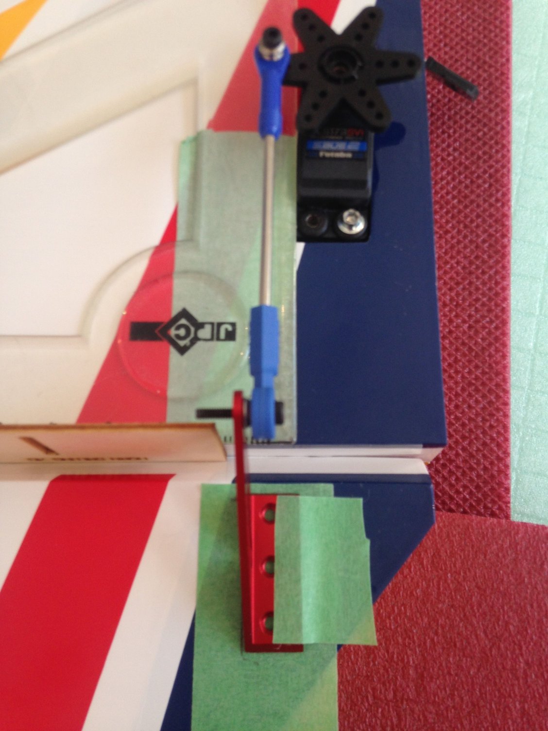
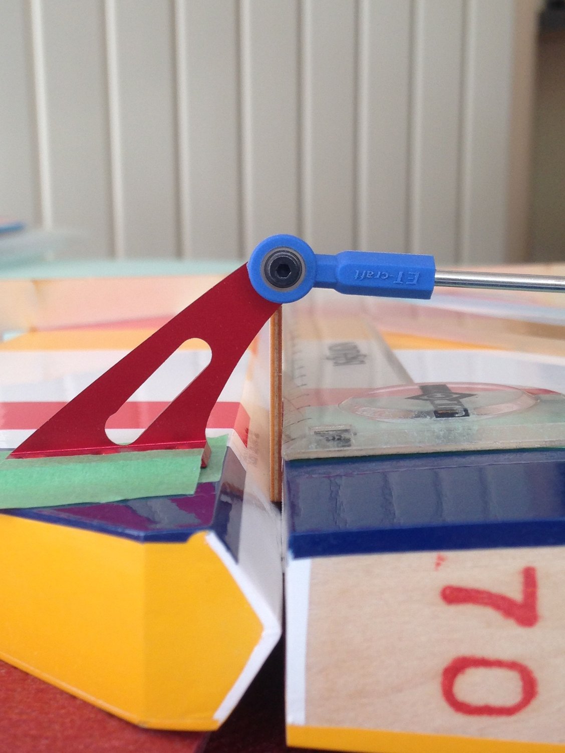
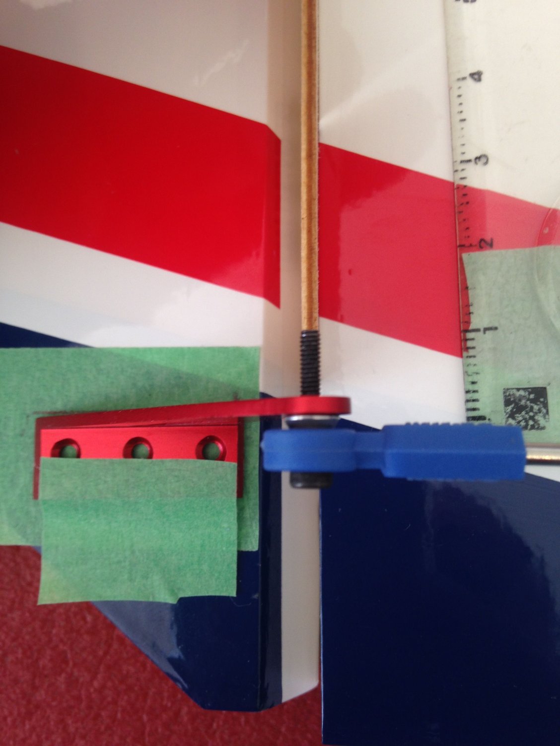
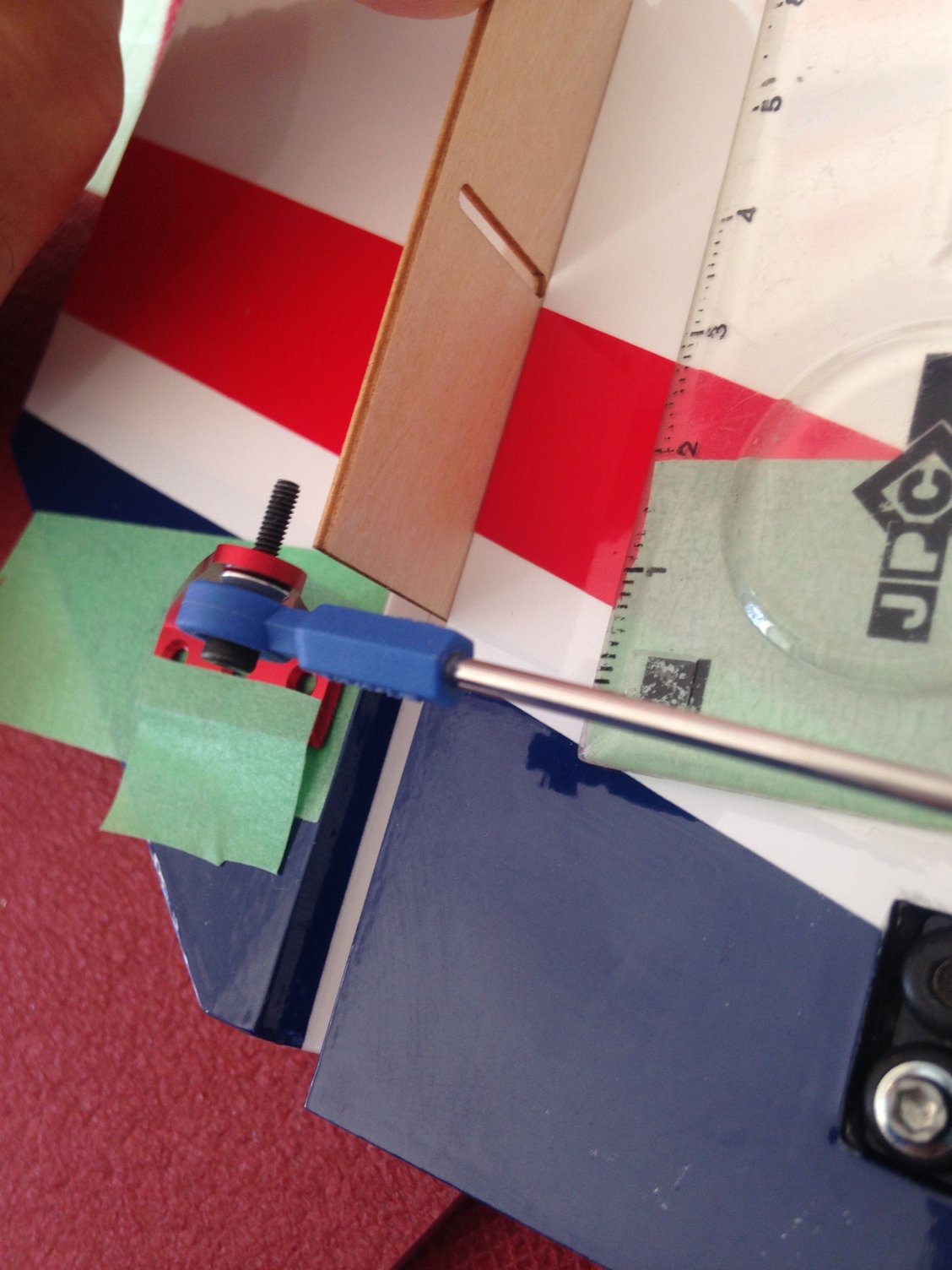
Hinges are glued in place with thin CA
I used two FUTABA BLS 173 SVI for the elevators and NISHIOKA control horns instead of the ones included in the kit
After positioning them and drilling the holes for the screws, I remove some covering material and use a pin before dropping some thin CA to reinforce the balsa.
I proceeded like this for all my planes and had no issue ….. until now
I use the standard Futaba horns and choice the arm the most parallel to the moving surface leading edge, then adjust with the SBUS, not the sub trim
Ball link and old red KATO ball bearings for the commands.
I ended up with this sticking foam I purchased in a Japanese store when shopping with GIICHI NARUKE and KEN HIROSE a few years ago . RIP NARUKE San.
I add a series of pictures of one of my LEADER G stab showing how to position the control horn with precision.
Last edited by J-P; 02-21-2025 at 11:02 AM.
The following users liked this post:
wattsup (02-21-2025)
02-25-2025 | 08:20 AM
#15
Thread Starter
My Feedback: (1)
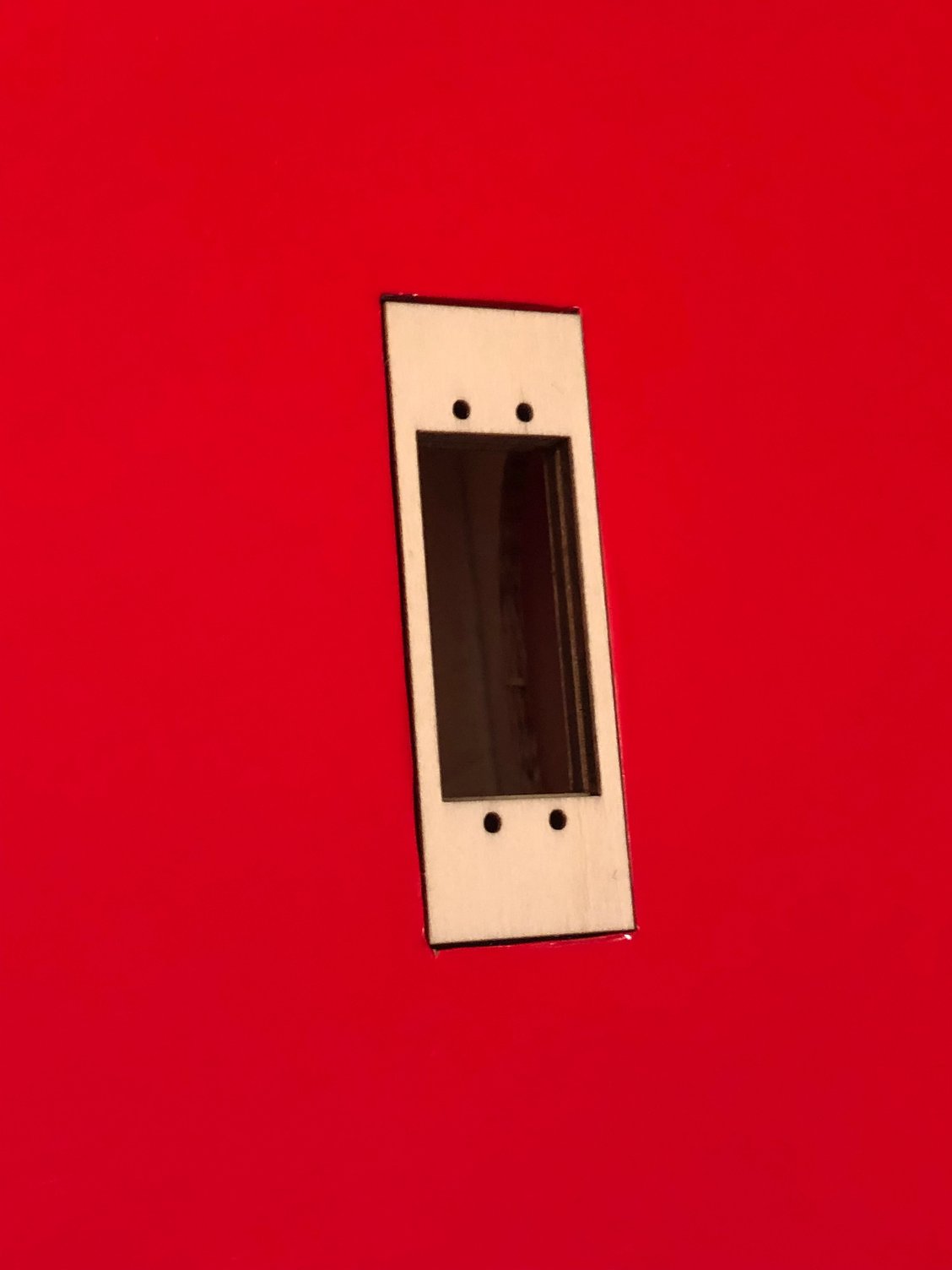
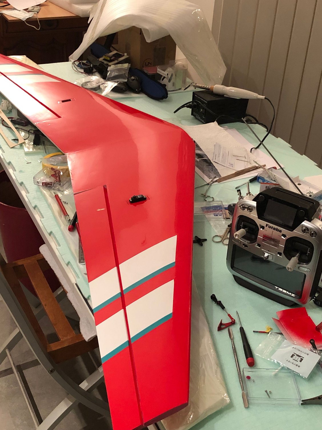
Installing the wings servos
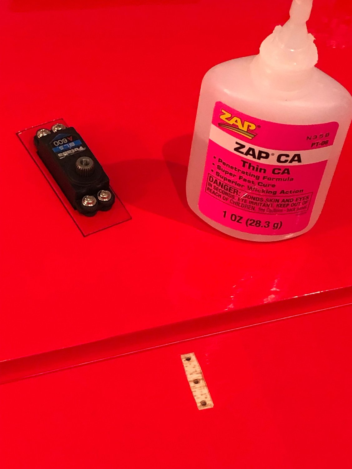
Starting with gluing the hinges with thin CA
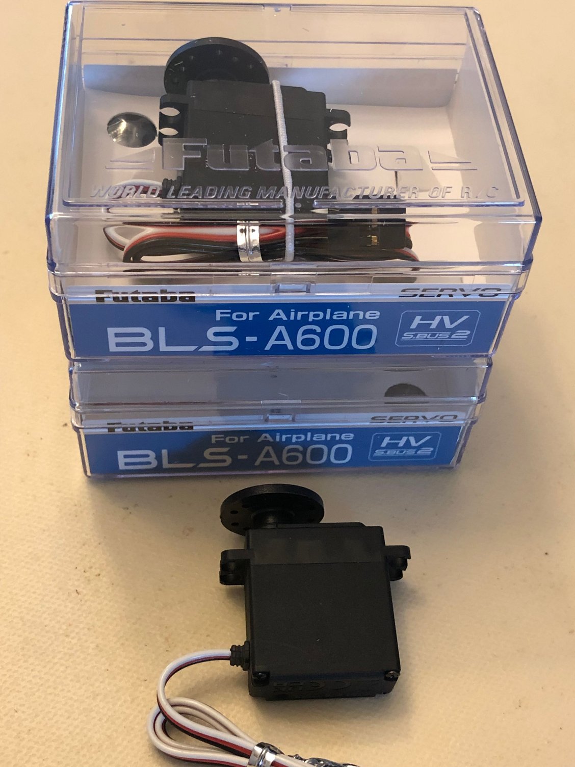
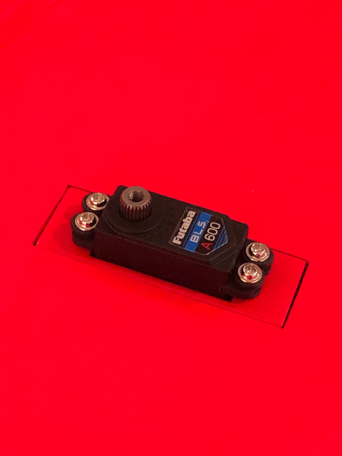
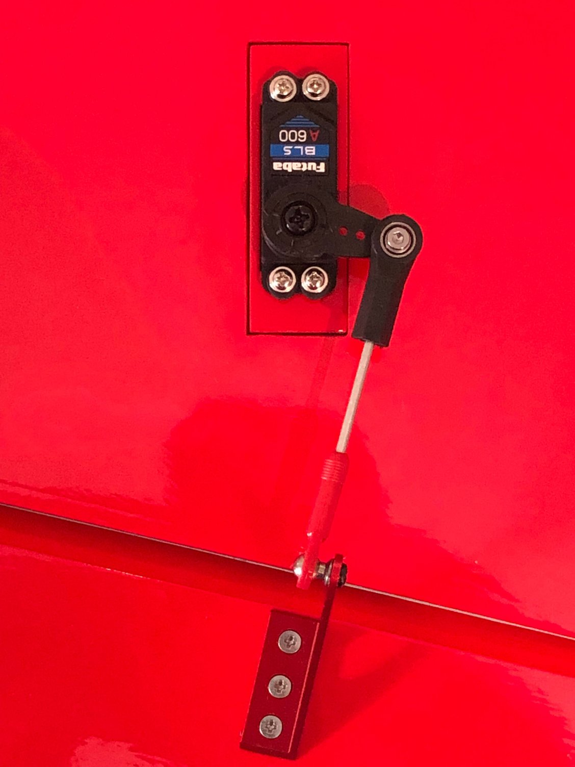
The BLS A600 is the servo replacing the very good BLS 173 phased out.
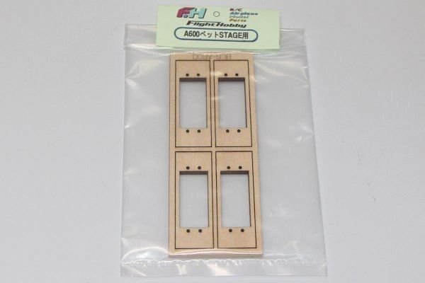
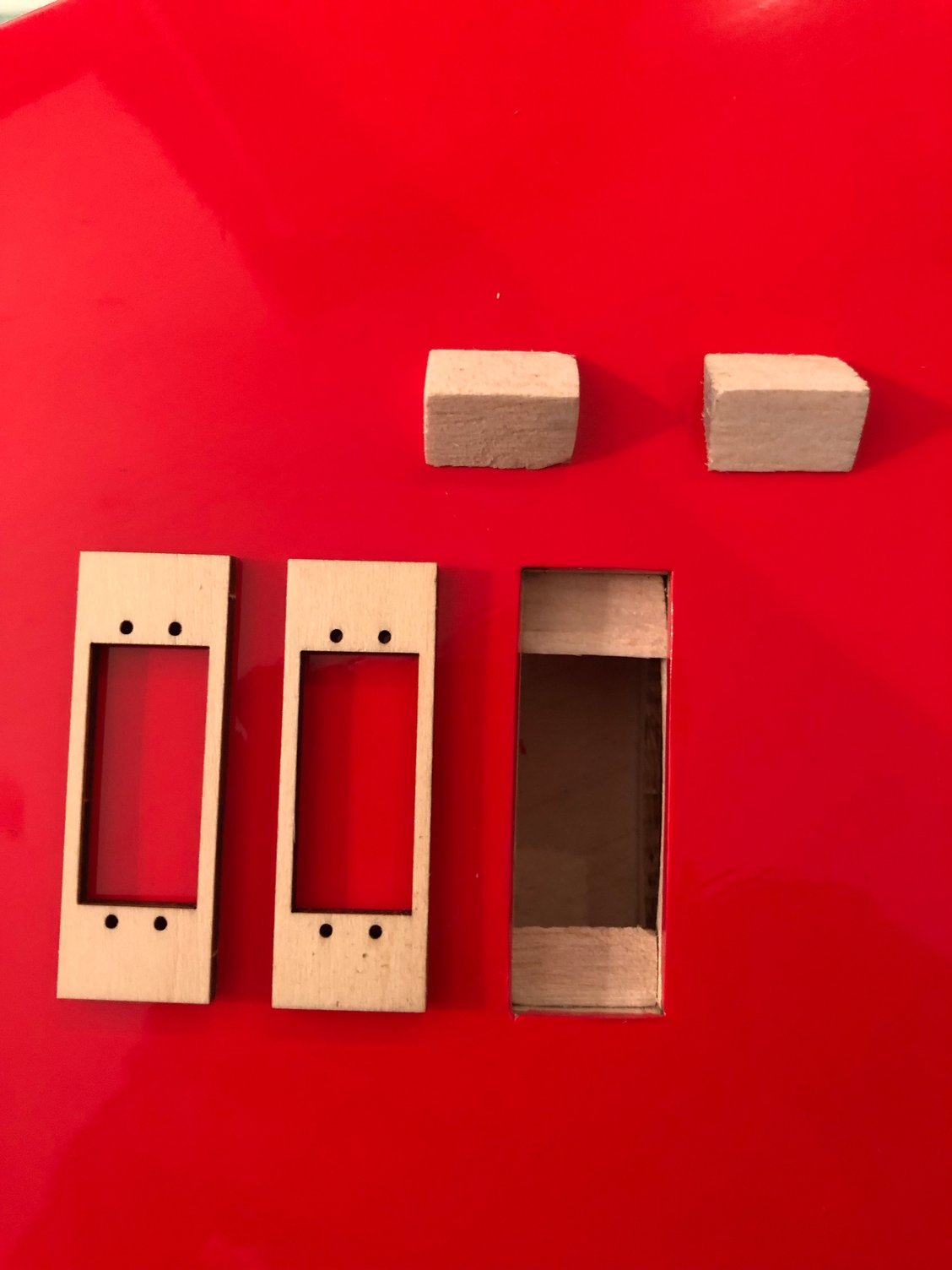
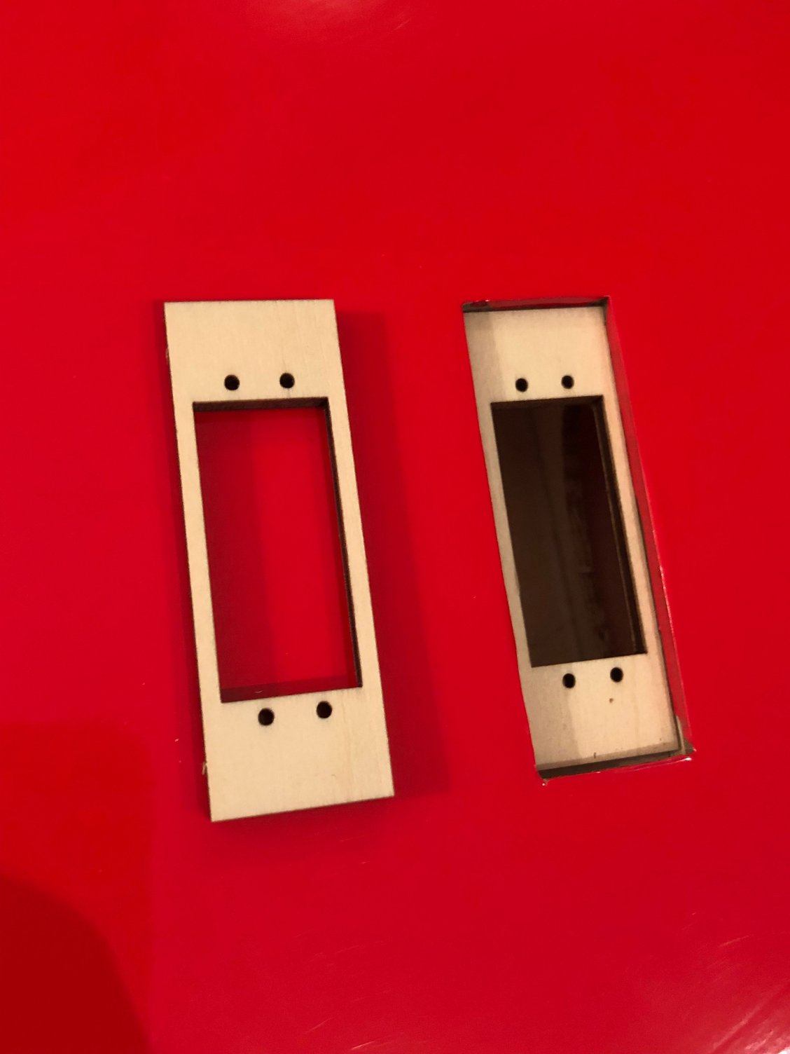
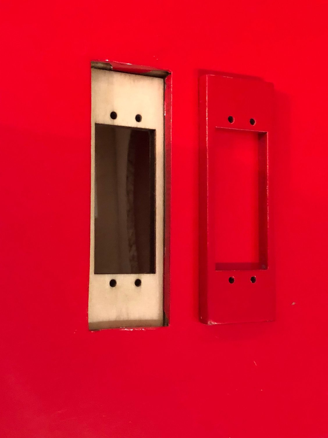
Of a different size, I had to use the Flight Hobby adaptor. It fits perfectly the BJ servo box of the MUSCLE CLOUD
I used two of them for each servo for a flush finish
Same technique to choose the right servo horn and installing the NISHIOKA 20 mm control horn
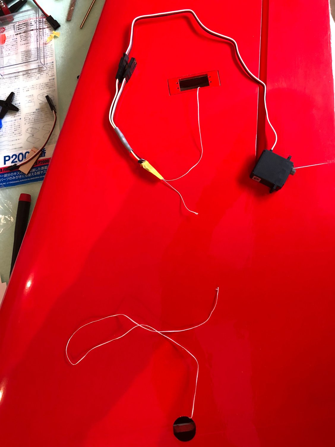
The BLS 173SVi was very convenient to use with a FUTABA Y in the wings
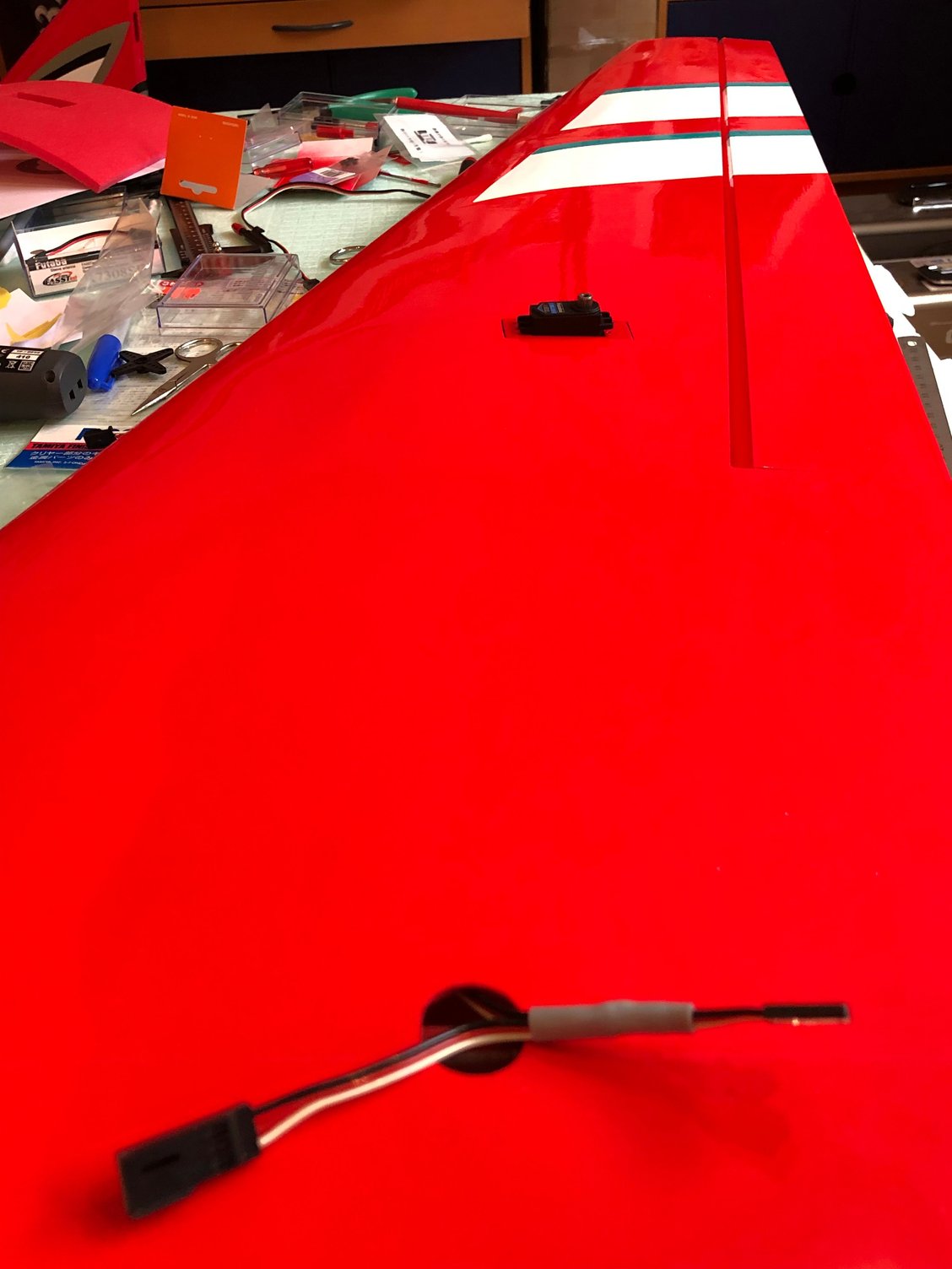
With the new BLS A600, I didn’t found other solution than installing the first servo with the FUTABA Y, and use a cord extension to hide in the wing ... for linking the second one . See pictures.
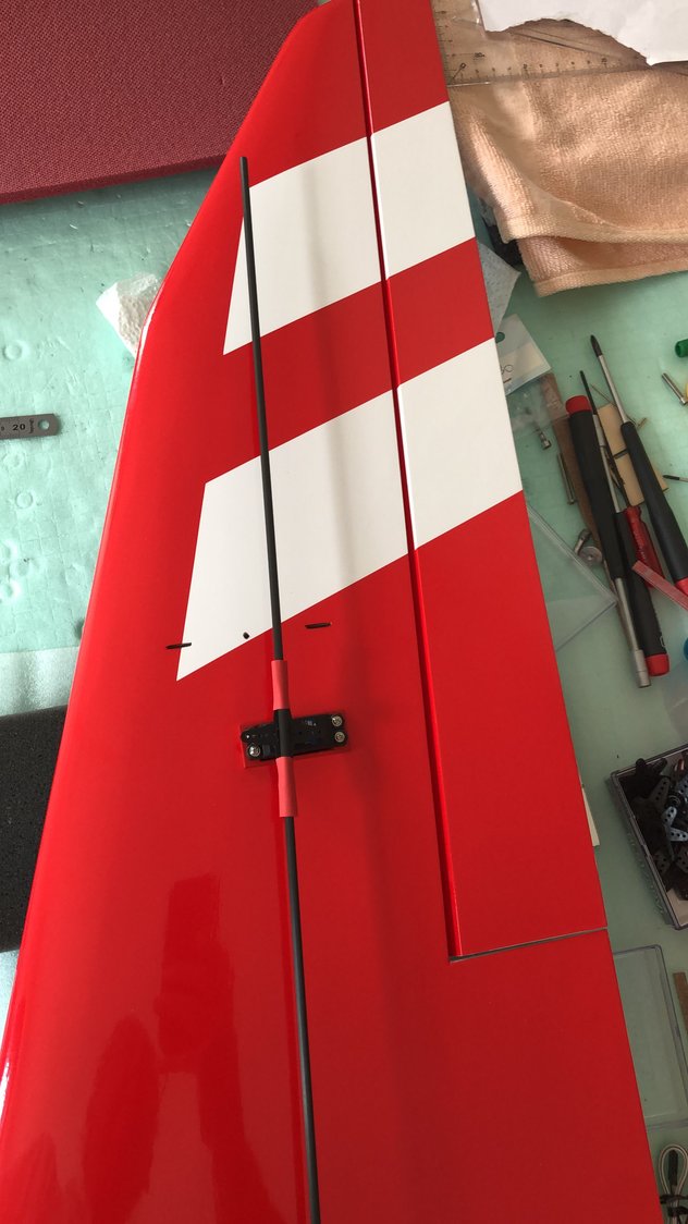
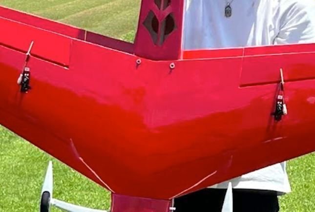
Due to the swept of the trailing edge wing, I reversed the output of the servo, otherwise the control rod overlapped the servo case.
See picture of the Japanese prototype
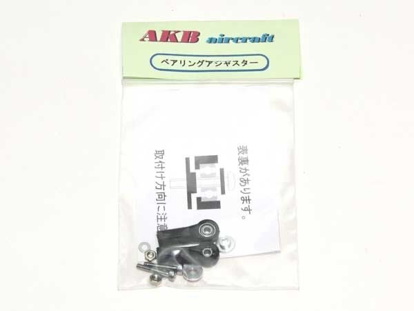
AKIBA ball bearing onto the servo horn and a ball link on the NISHIOKA 20 mm control horn
Same technique with the LEADER G wings
Starting with gluing the hinges with thin CA
The BLS A600 is the servo replacing the very good BLS 173 phased out.
Of a different size, I had to use the Flight Hobby adaptor. It fits perfectly the BJ servo box of the MUSCLE CLOUD
I used two of them for each servo for a flush finish
Same technique to choose the right servo horn and installing the NISHIOKA 20 mm control horn
The BLS 173SVi was very convenient to use with a FUTABA Y in the wings
With the new BLS A600, I didn’t found other solution than installing the first servo with the FUTABA Y, and use a cord extension to hide in the wing ... for linking the second one . See pictures.
Due to the swept of the trailing edge wing, I reversed the output of the servo, otherwise the control rod overlapped the servo case.
See picture of the Japanese prototype
AKIBA ball bearing onto the servo horn and a ball link on the NISHIOKA 20 mm control horn
Same technique with the LEADER G wings
Last edited by J-P; 02-25-2025 at 08:23 AM.
The following users liked this post:
wattsup (02-25-2025)
03-03-2025 | 08:18 AM
#16
Thread Starter
My Feedback: (1)
Installation of the bottom wing
I started by checking the location of the wing dowels and retaining screws on the fuselage.
As everything is done by CNC, this is perfect
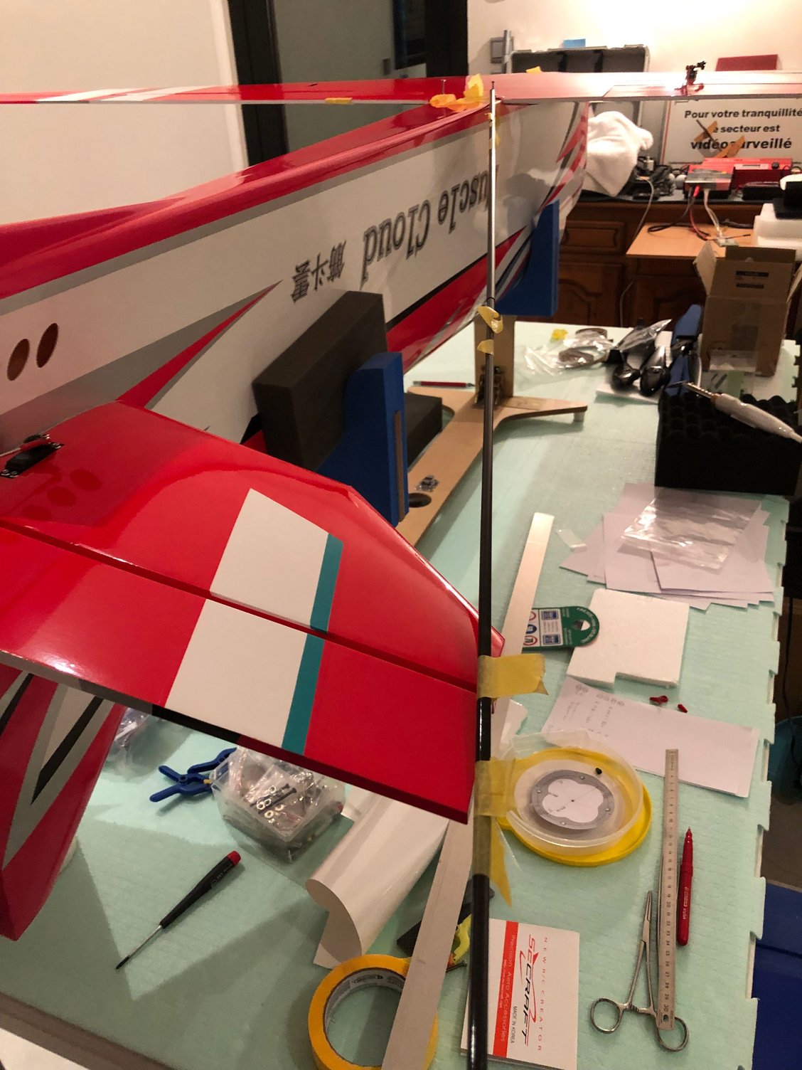
I installed the stabs and checked an equal distance from the wing bolts to the stabs tips
I use two carbon rods to check the equal lengths
Positioning of the stabs is perfect
Then I checked the position of the wings, tips to fuselage, tips to leg plate, tips to stabs tips before drilling the trailing edge wing and installing the plywood insuring the right positioning of the bottom wing
All square.
The wings are the same as the ULTIMATE BISIDE, and you can read STEVE HANNAH comment's here
BJ Craft Ultimate Biside Build
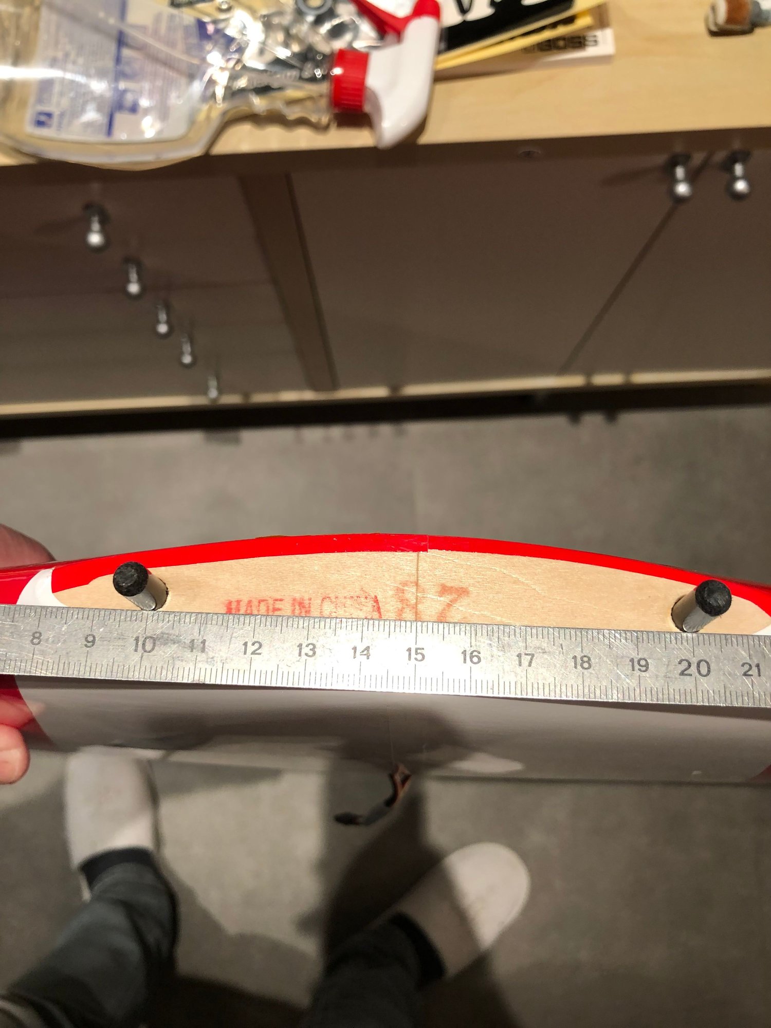

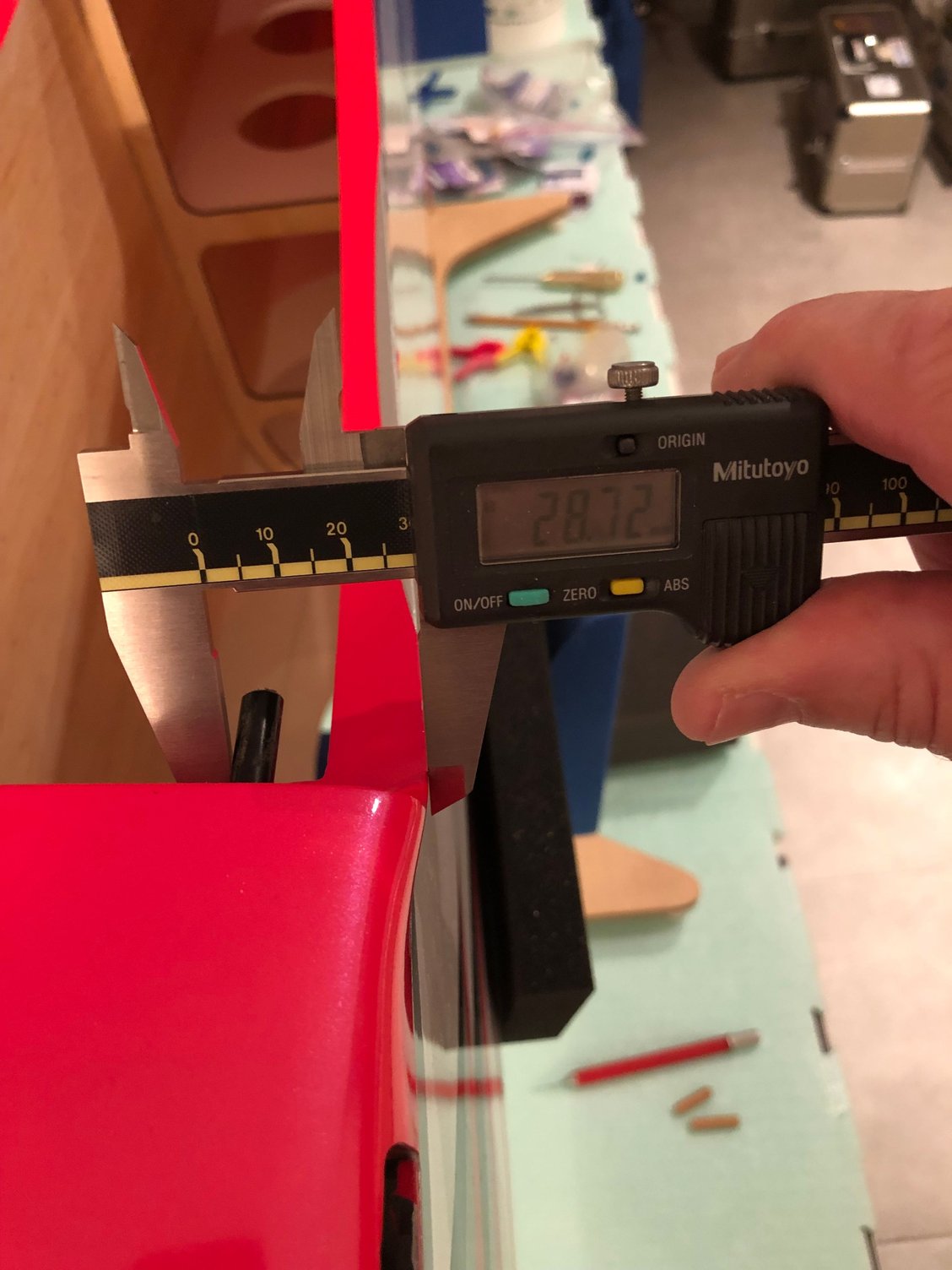
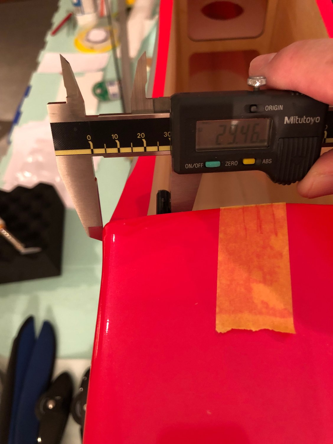

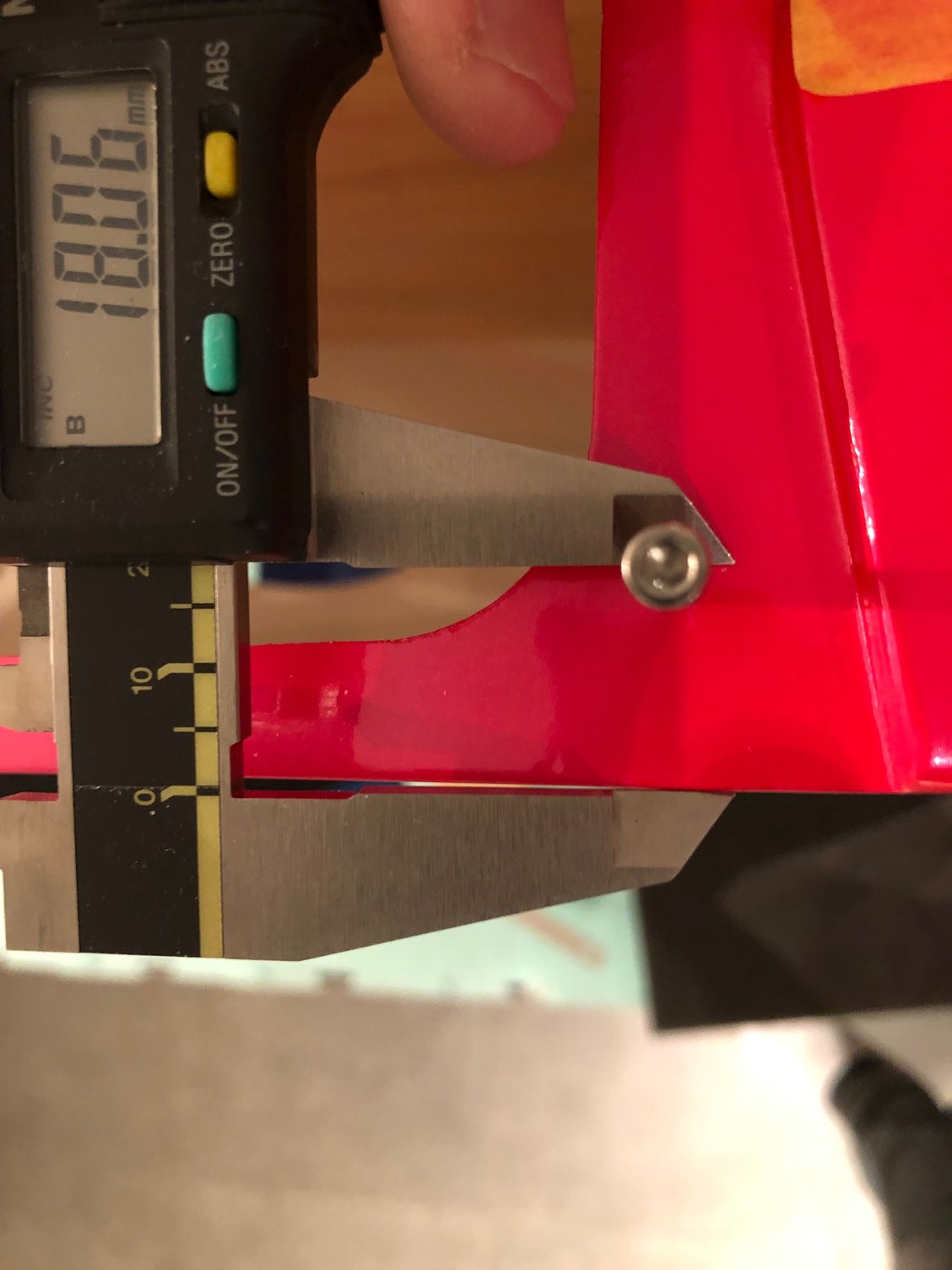


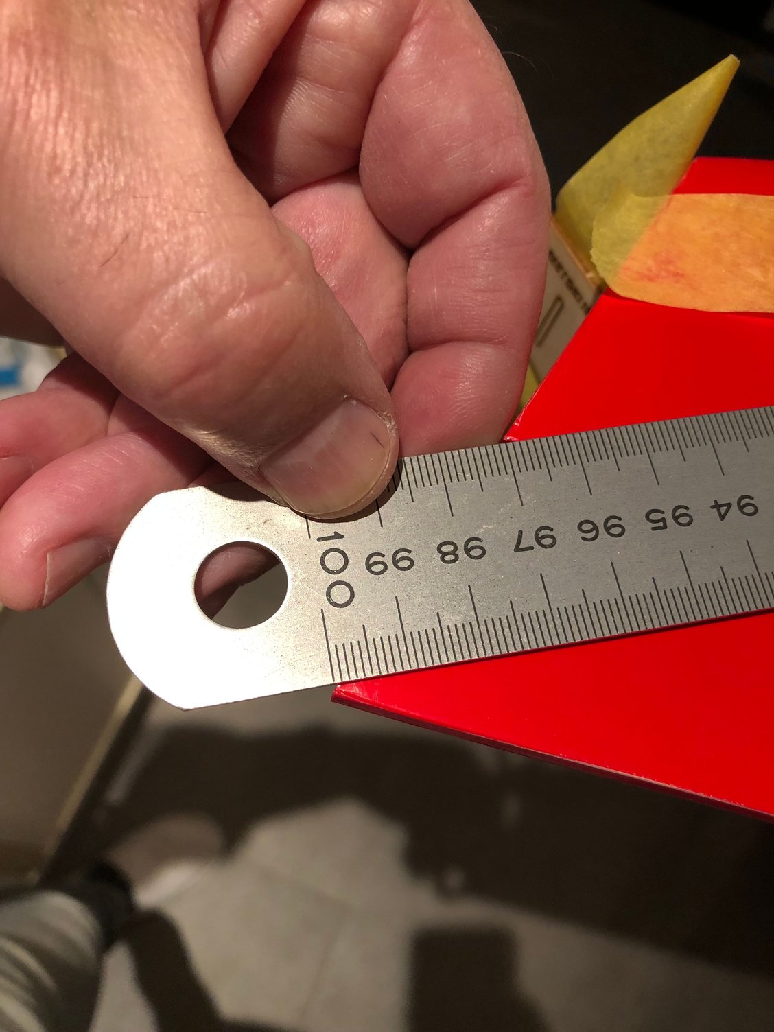

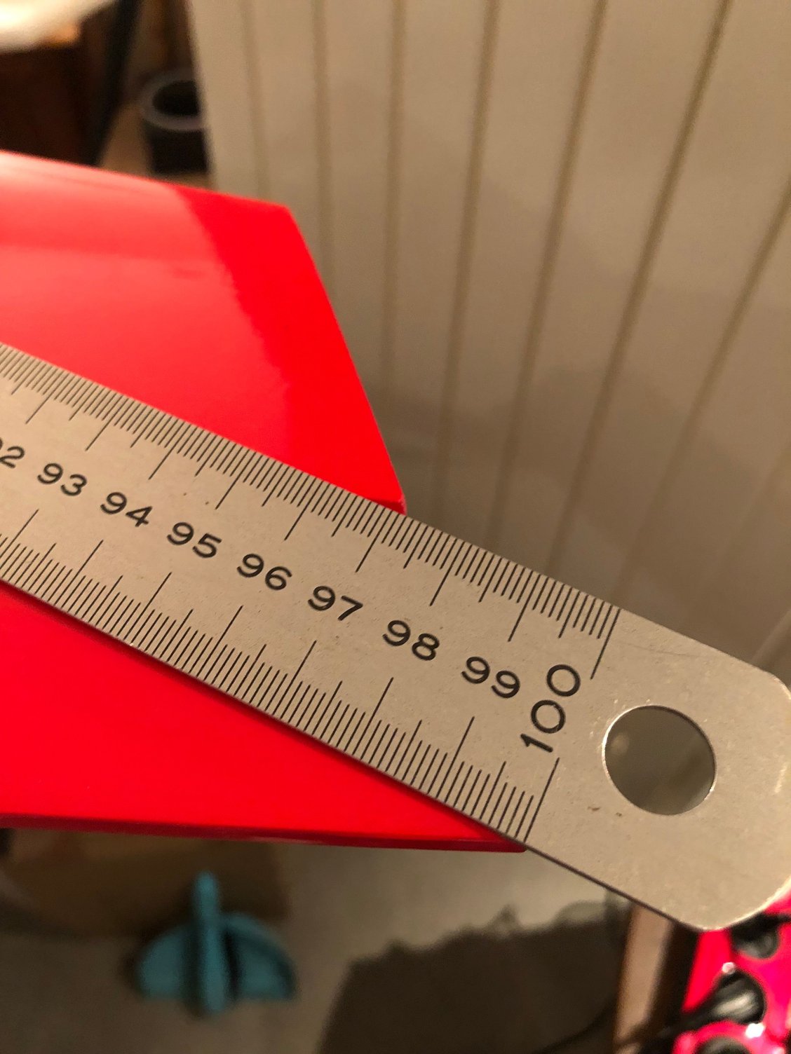
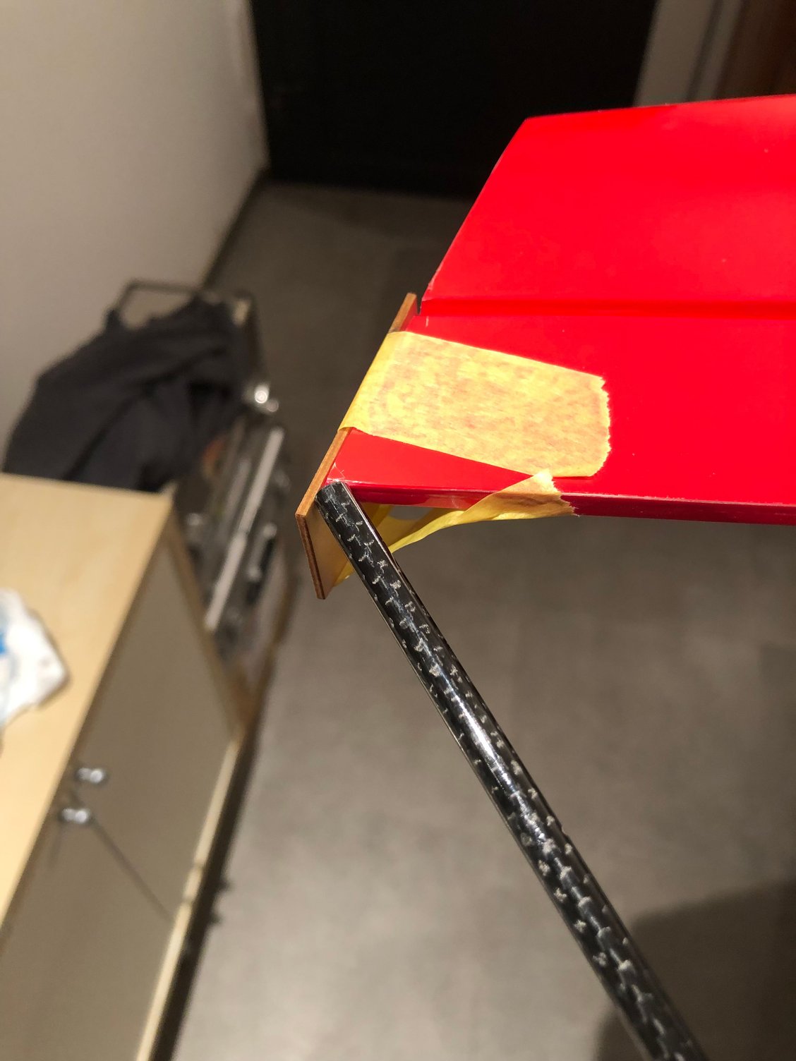
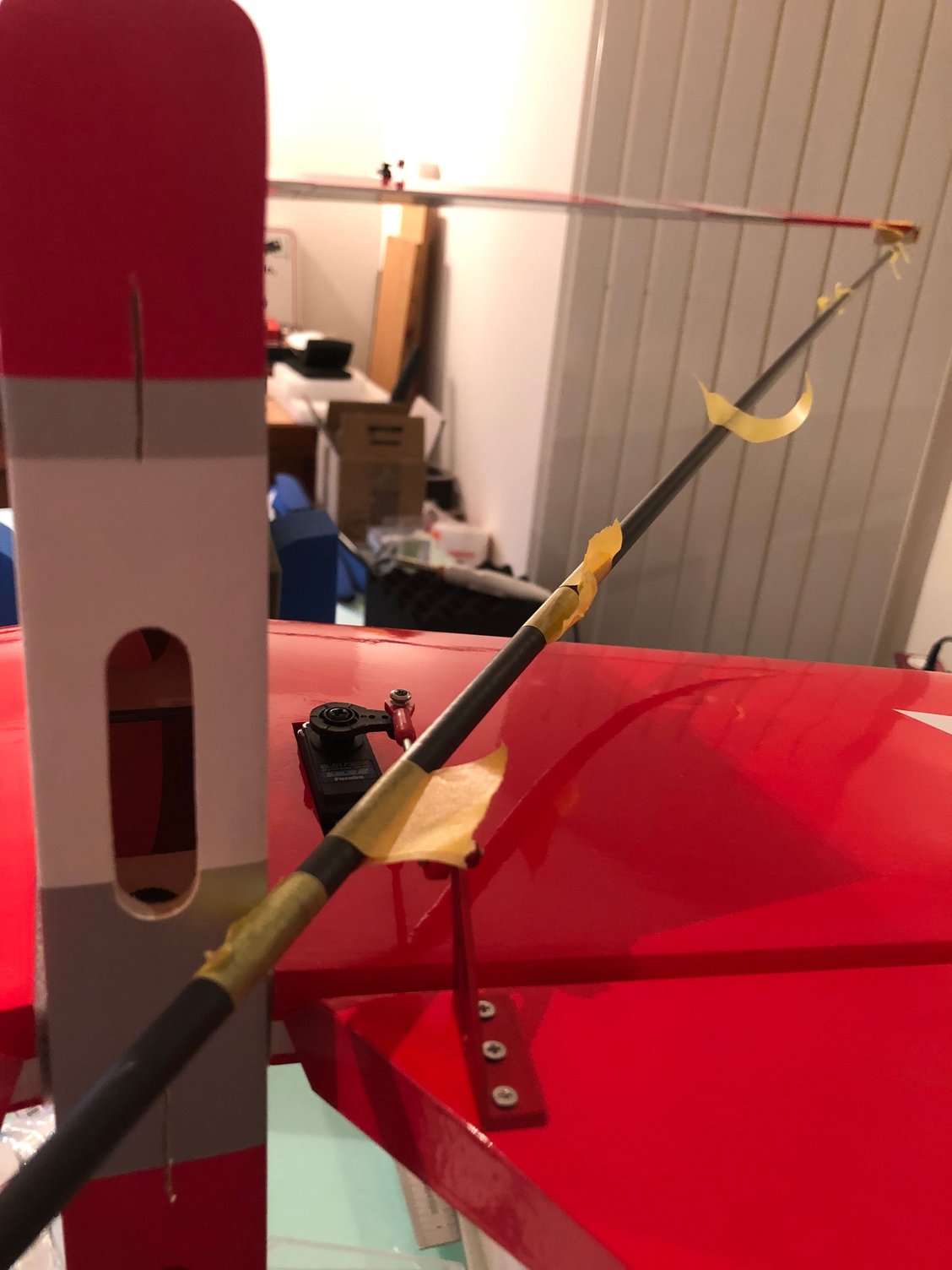


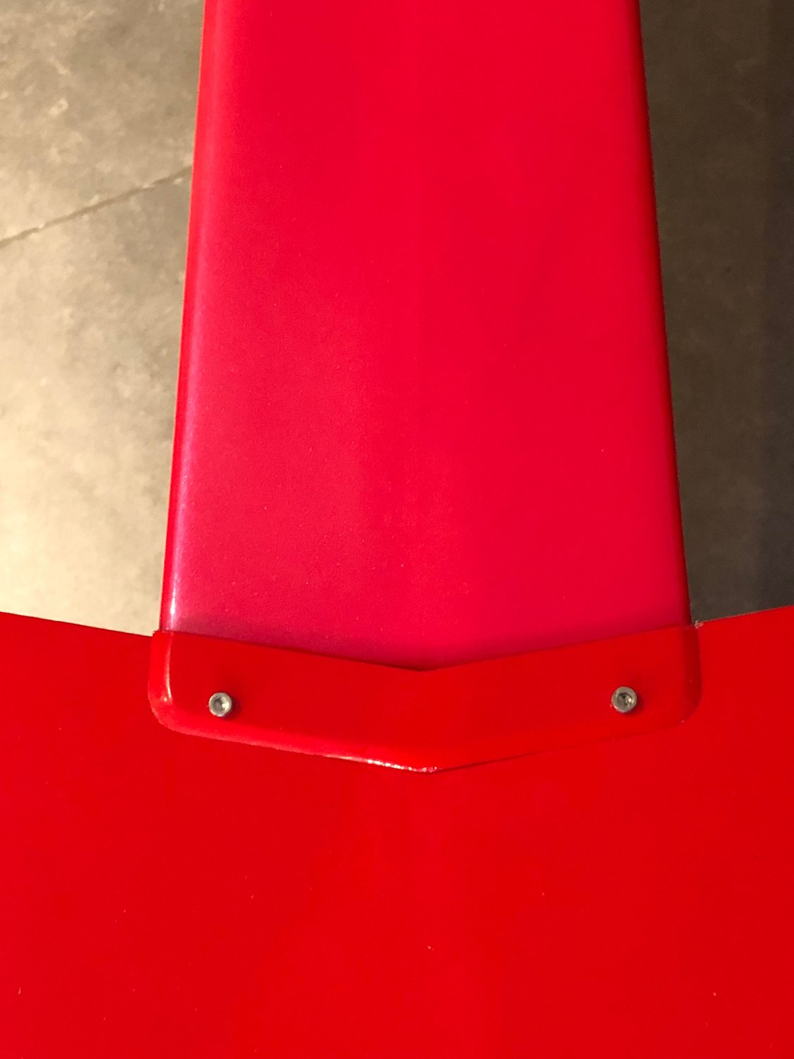
I started by checking the location of the wing dowels and retaining screws on the fuselage.
As everything is done by CNC, this is perfect
I installed the stabs and checked an equal distance from the wing bolts to the stabs tips
I use two carbon rods to check the equal lengths
Positioning of the stabs is perfect
Then I checked the position of the wings, tips to fuselage, tips to leg plate, tips to stabs tips before drilling the trailing edge wing and installing the plywood insuring the right positioning of the bottom wing
All square.
The wings are the same as the ULTIMATE BISIDE, and you can read STEVE HANNAH comment's here
BJ Craft Ultimate Biside Build
The following users liked this post:
wattsup (03-30-2025)
03-30-2025 | 12:12 AM
#17
Thread Starter
My Feedback: (1)
Back home, it's now time to complete the MUSCLE CLOUD.
Having received the A 600 FUTABA servos, both wings are now ready.
This servo has different characteristics from the BLS 173, noisy when finding neutral.
I set smoother ON and started with 0.30 degree dead-band.
Next step is to have the engine mount installed.
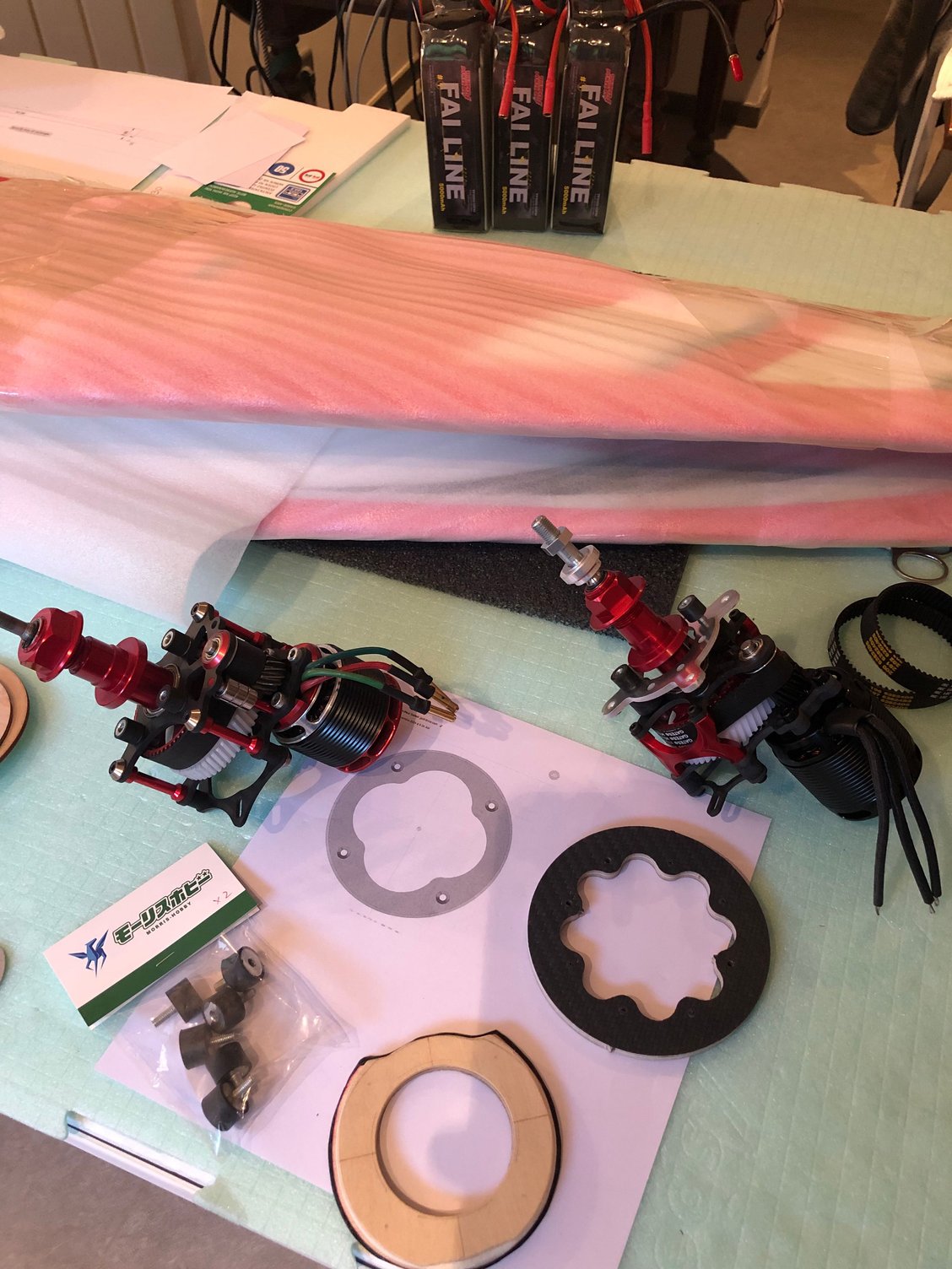
I choiced the option of the CNC part to come soon ..... in 6 mm plywood , the right thickness for motor installation.
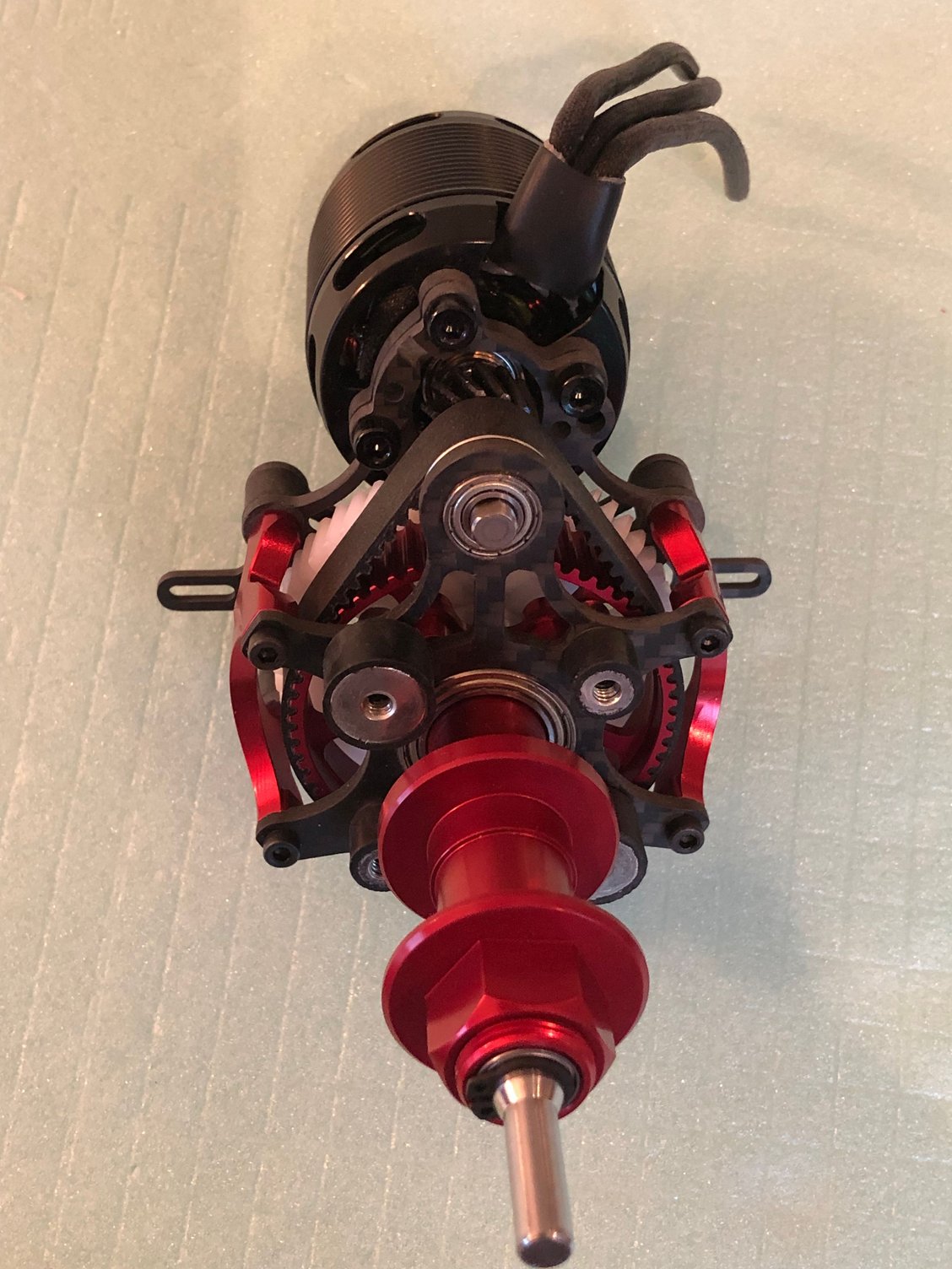
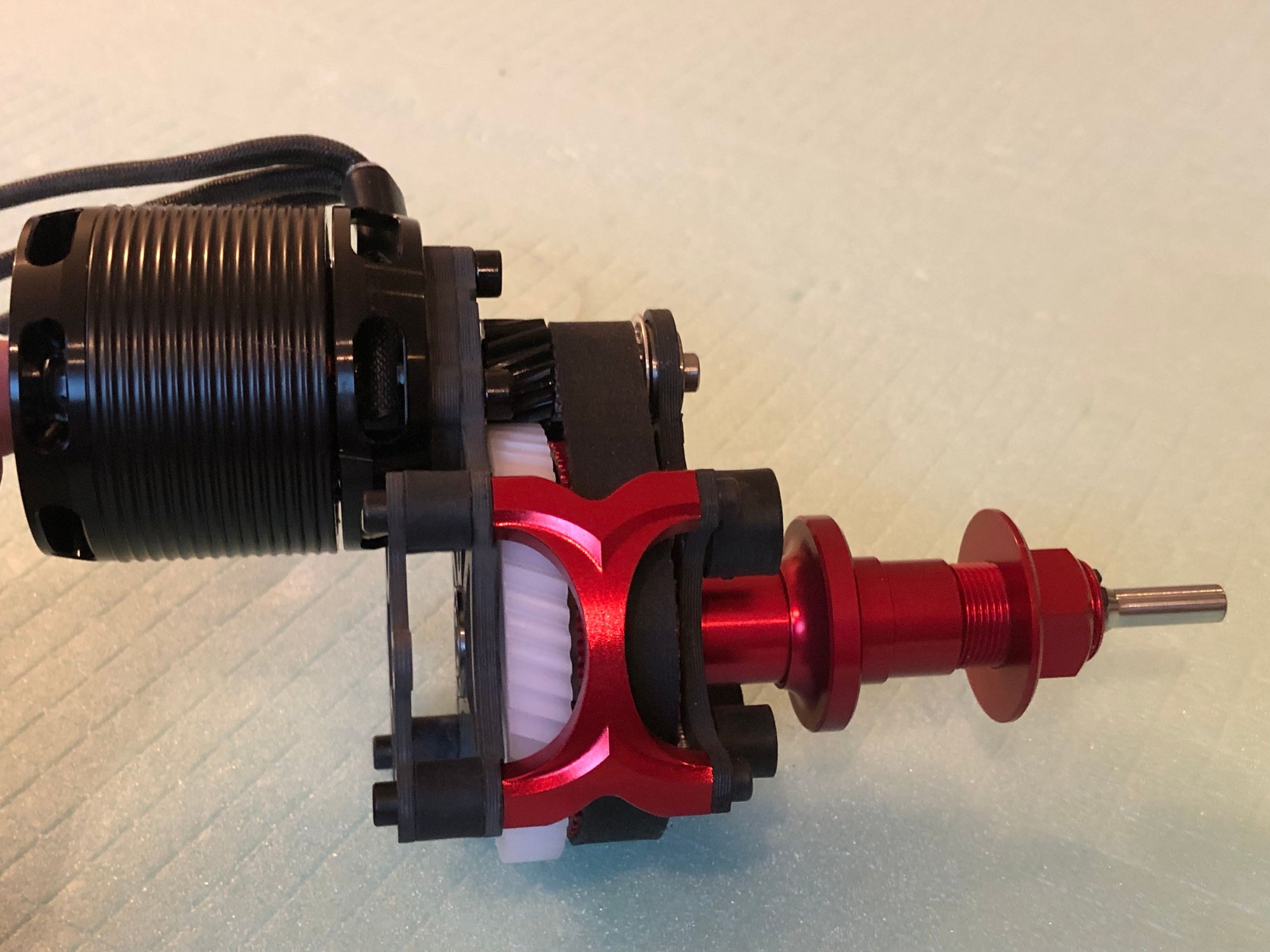
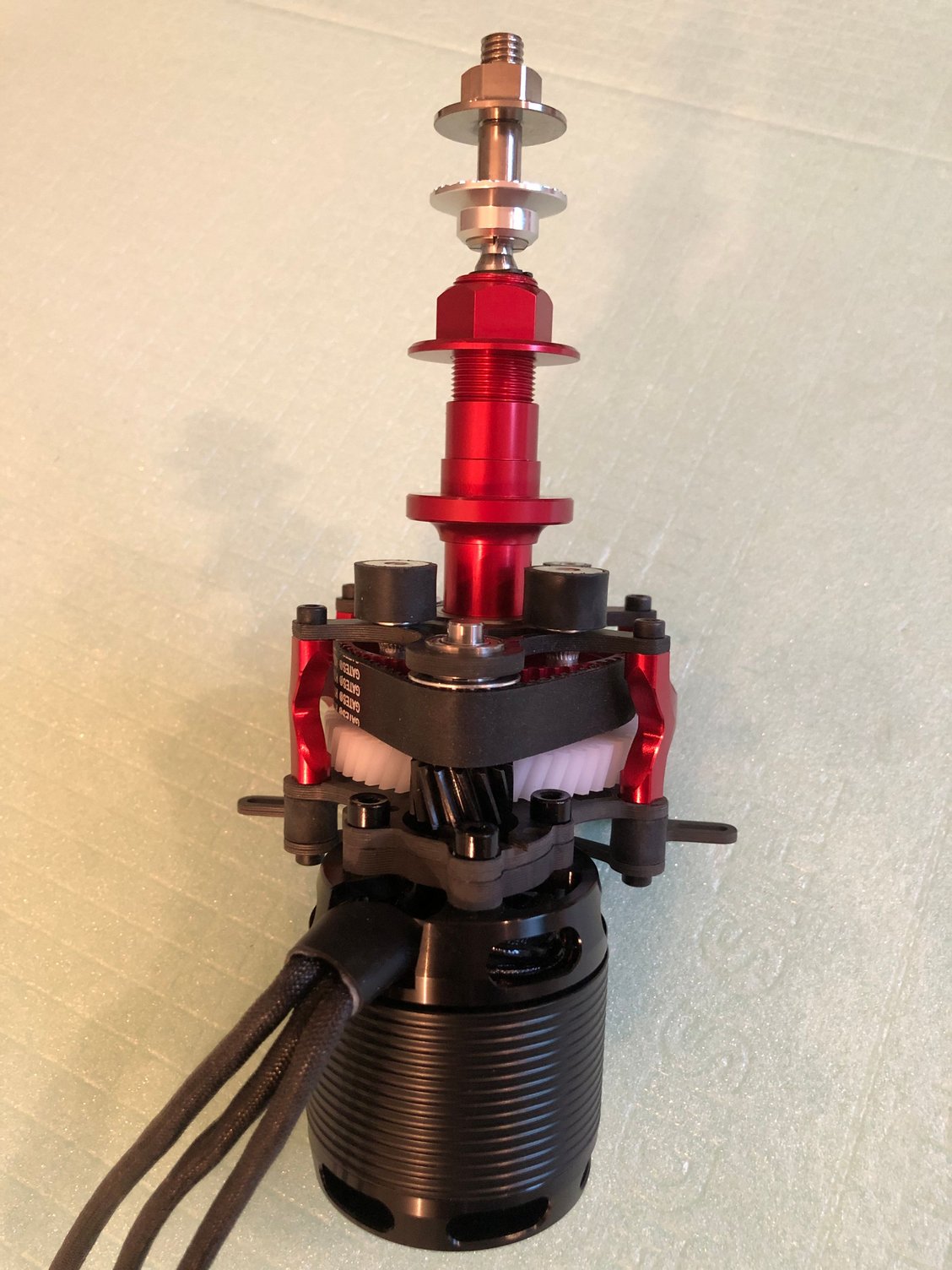
Engine is the ADVERRUN V3 with the EGODRIFT, and I have choice for the ESC, starting with the D3, my favorite, then planning to give a try to the VLV.
I use the 50products part H 25 AD instead of the std one, fits perfectly the ADVERRUN V3 shaft.

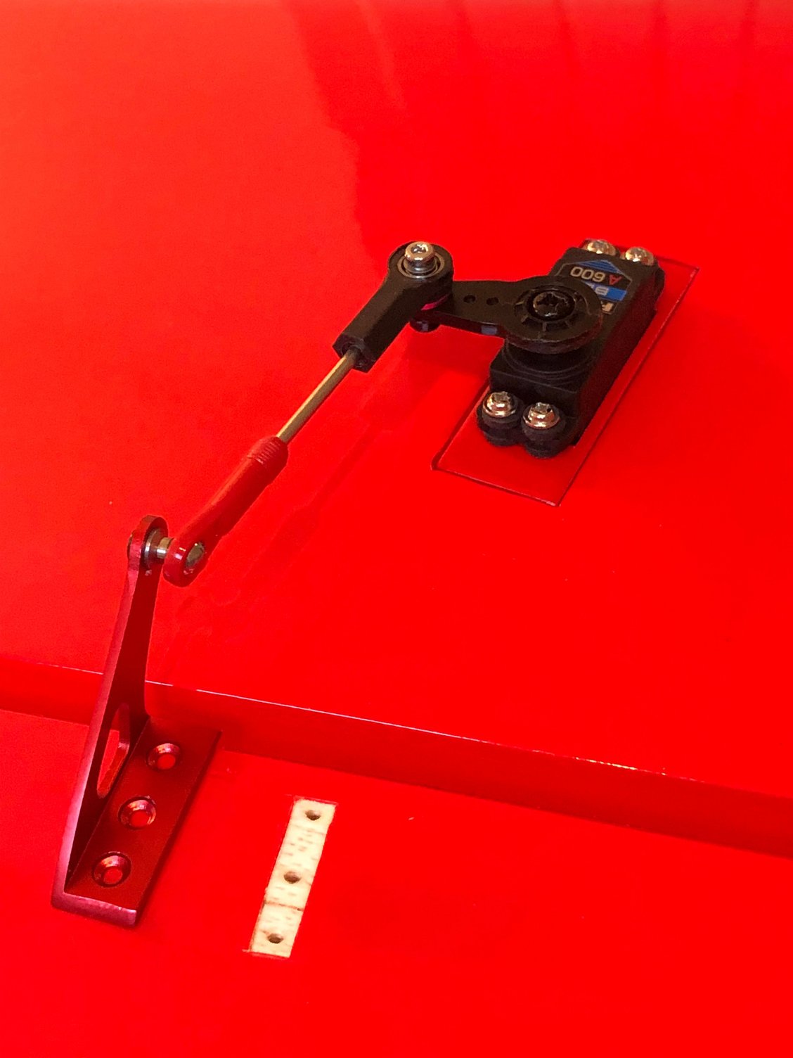
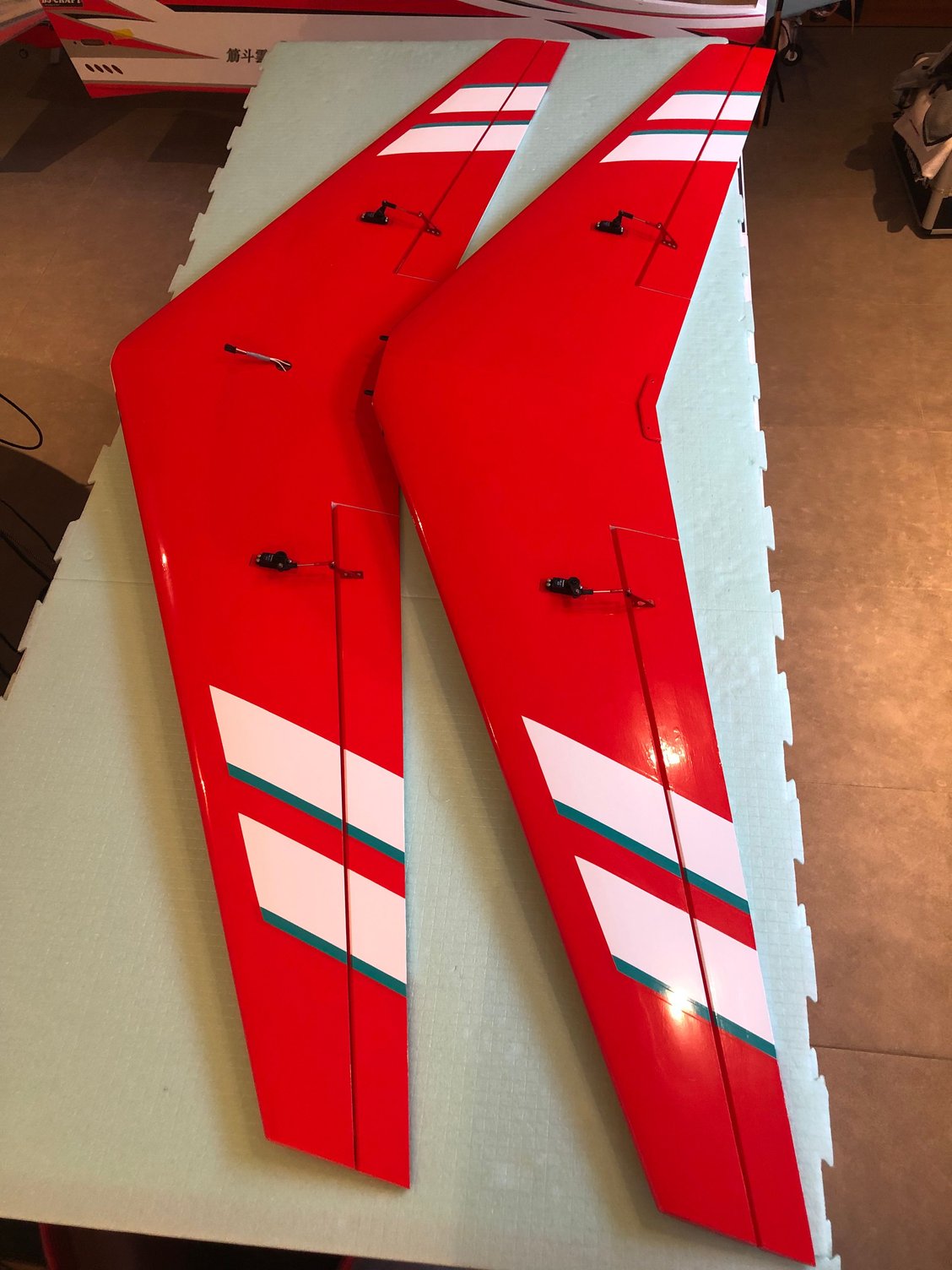
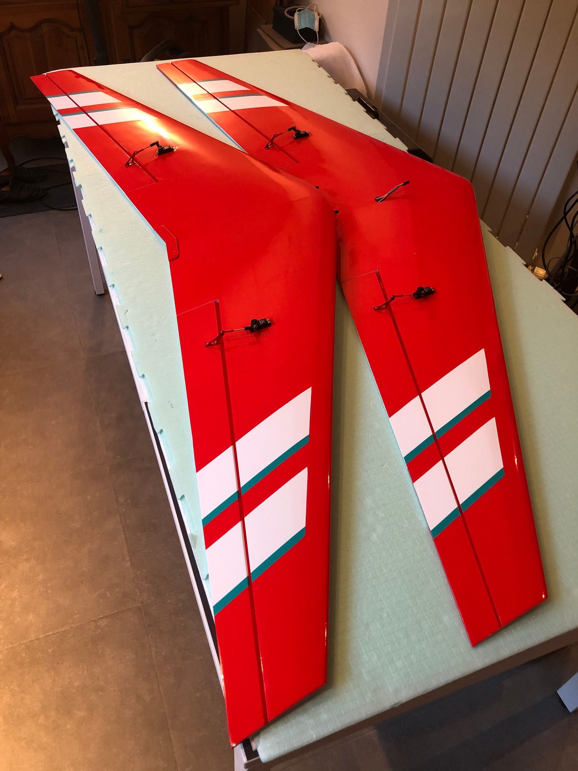
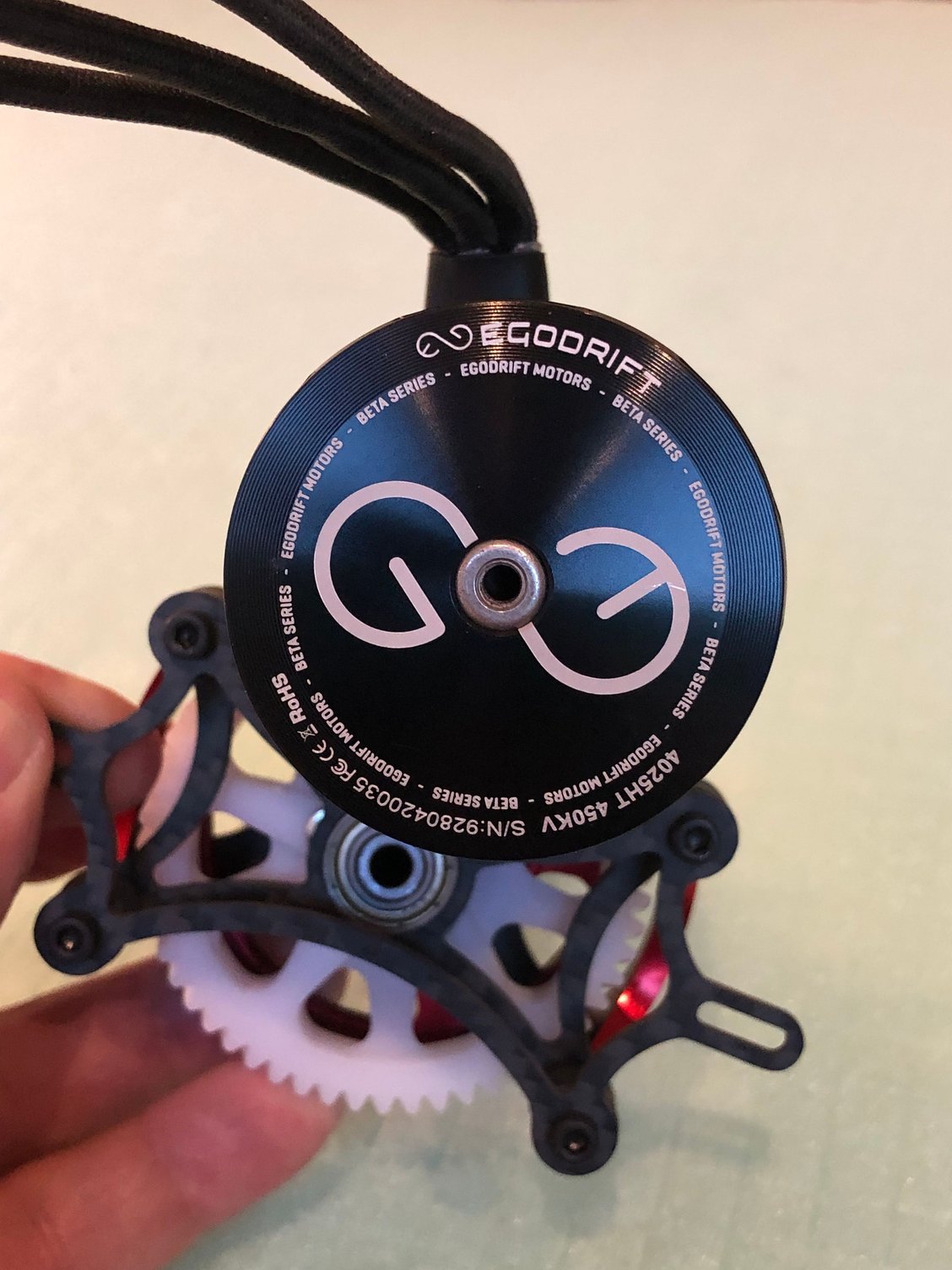
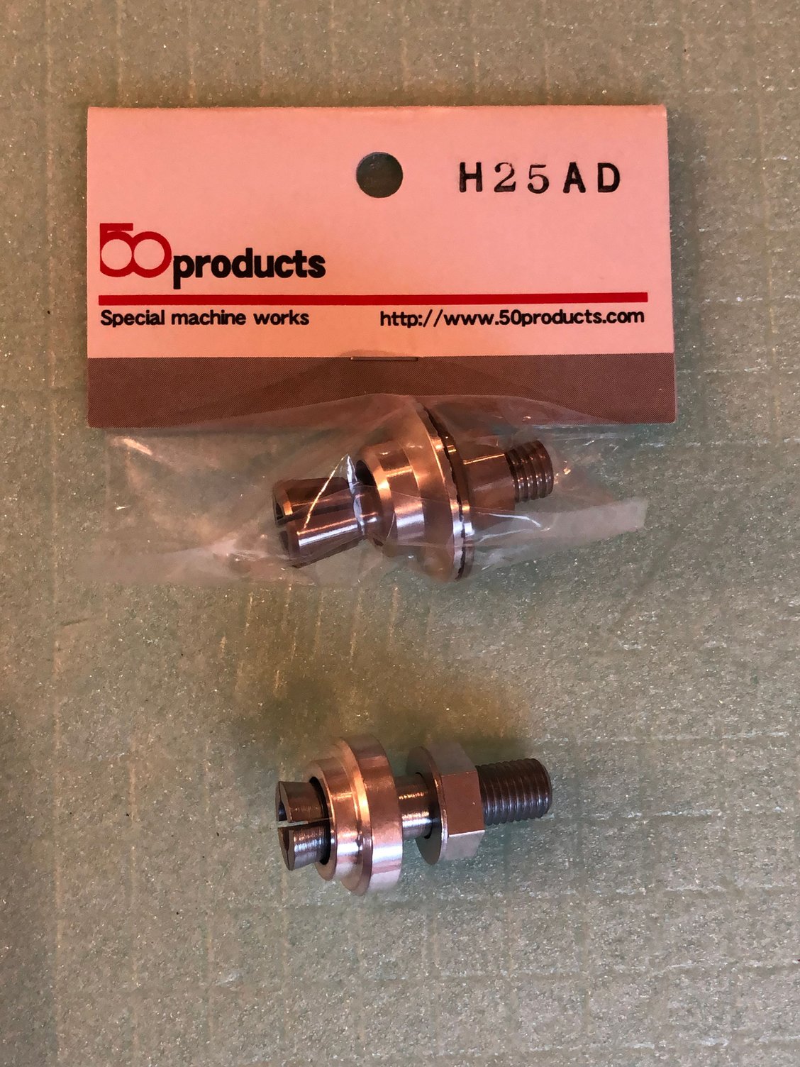
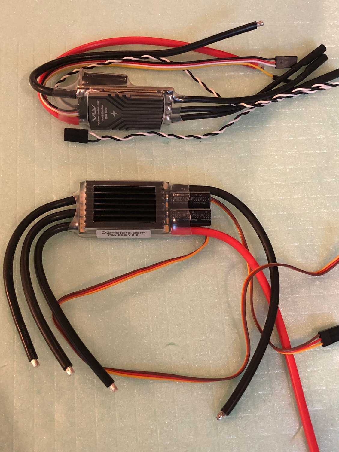
Having received the A 600 FUTABA servos, both wings are now ready.
This servo has different characteristics from the BLS 173, noisy when finding neutral.
I set smoother ON and started with 0.30 degree dead-band.
Next step is to have the engine mount installed.
I choiced the option of the CNC part to come soon ..... in 6 mm plywood , the right thickness for motor installation.
Engine is the ADVERRUN V3 with the EGODRIFT, and I have choice for the ESC, starting with the D3, my favorite, then planning to give a try to the VLV.
I use the 50products part H 25 AD instead of the std one, fits perfectly the ADVERRUN V3 shaft.
The following users liked this post:
wattsup (03-30-2025)
04-02-2025 | 10:58 PM
#18
Thread Starter
My Feedback: (1)
Installation of the top wing
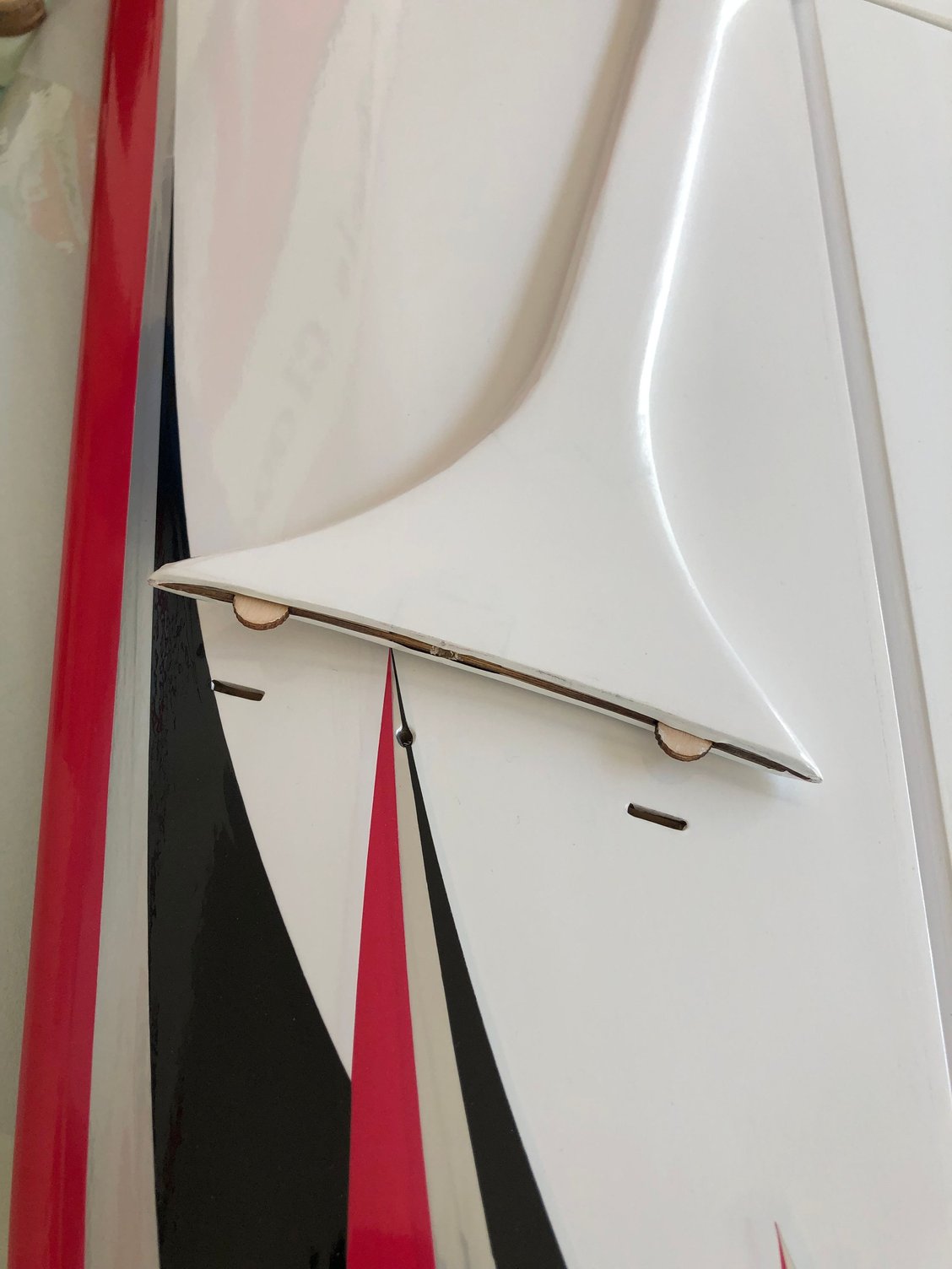
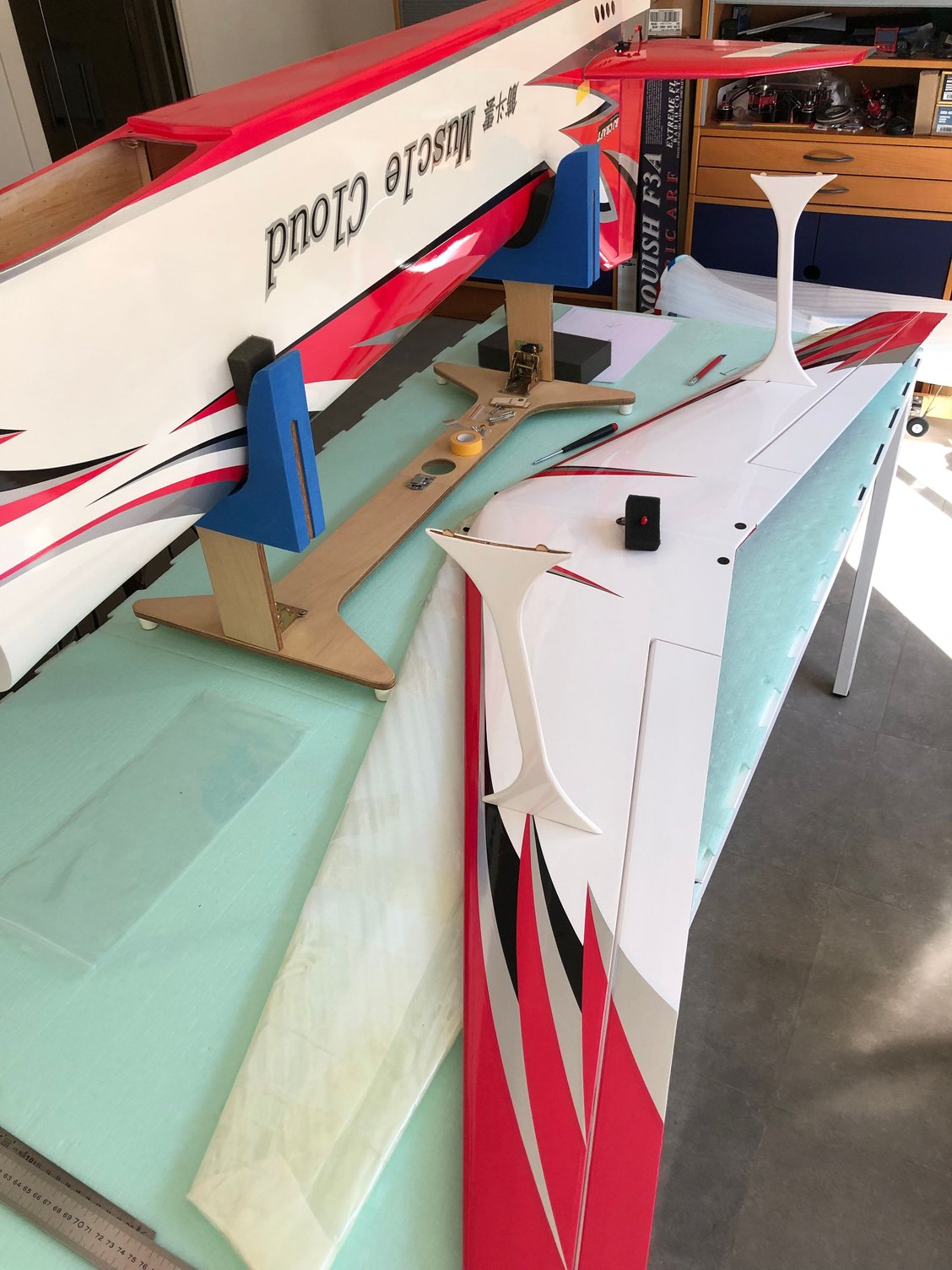
With just 2 screws to position the wing perfectly aligned with the bottom wing and centered on the fuselage, this operation take time.
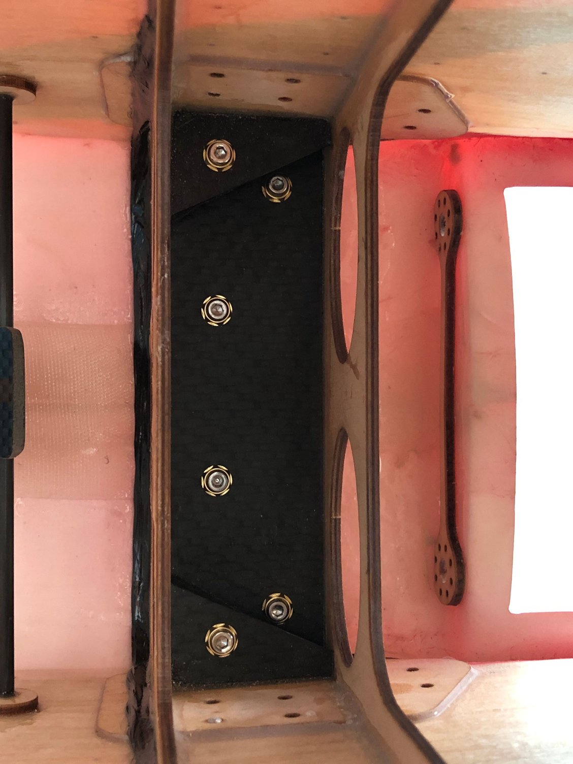
I decided to remove the blind nuts already installed in the fuselage for the bottom wing, and to use Heavy Duty 3 mm MP JETS.
With the wing positioned, I glued in place the inserts with 30 mn ZAP Epoxy.
For the top wing I drilled the top fuselage with the wing in position with a 3 mm bit through the wing, and had a small decalage in the holes already pre drilled.
Preparing the wings for the struts is easy when you know the location ...
Wings done 😎😎
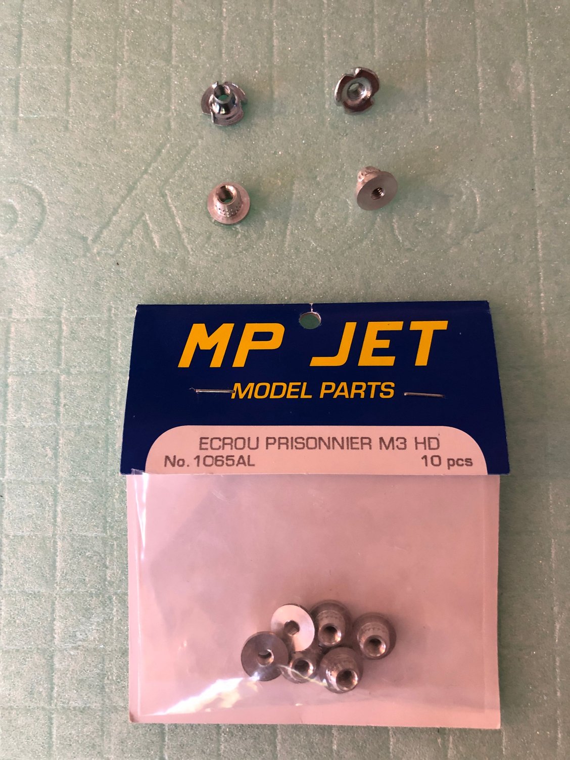
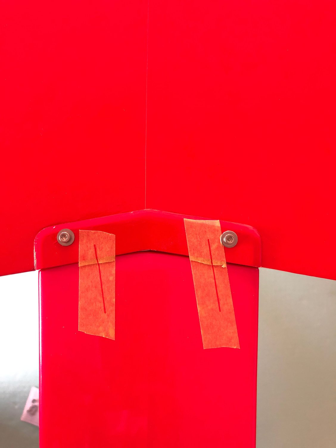

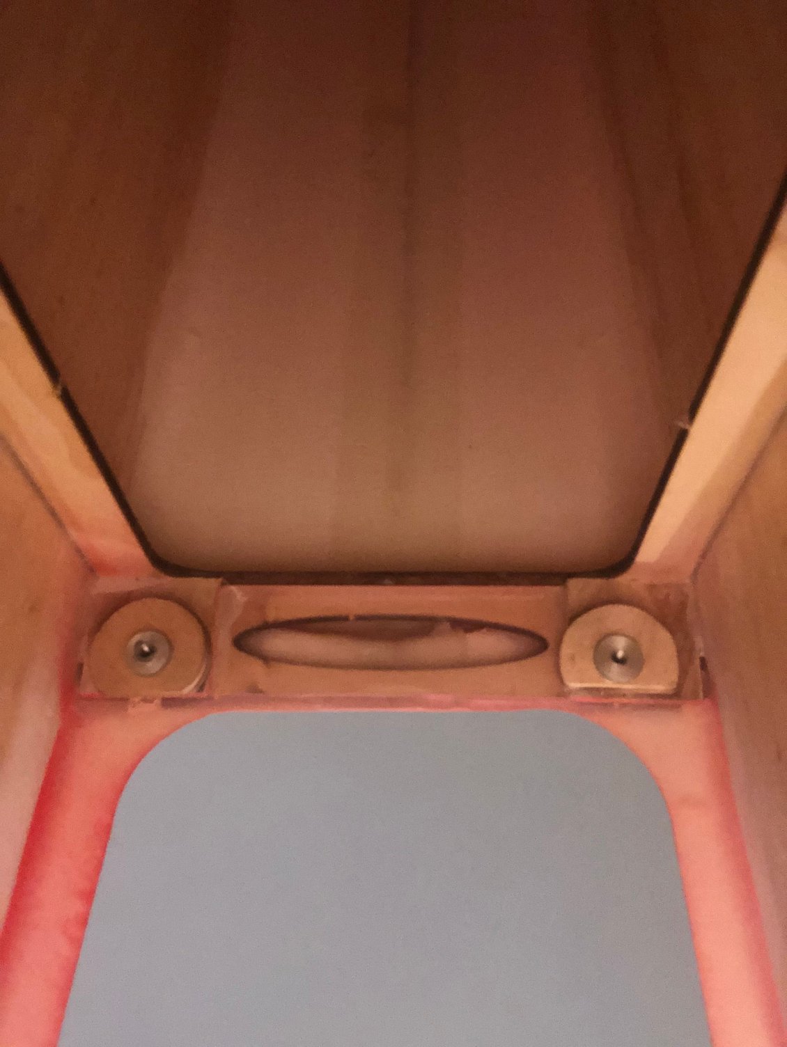
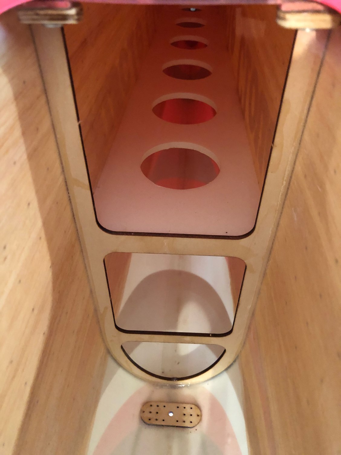
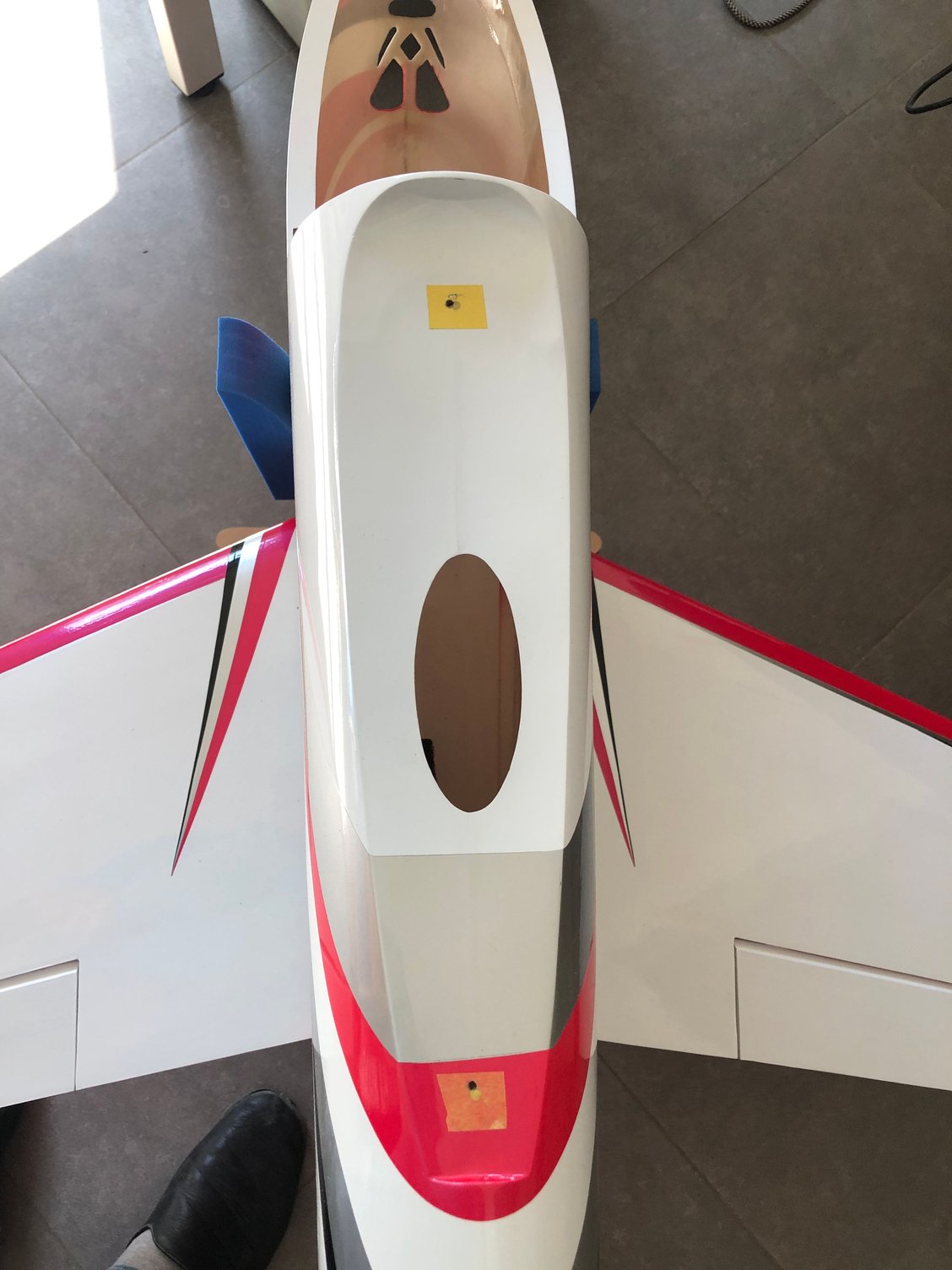
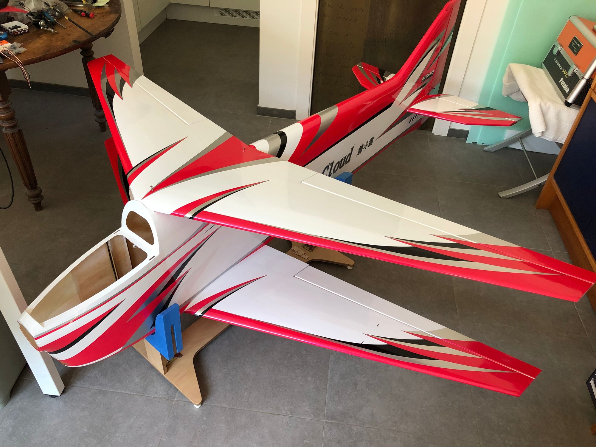
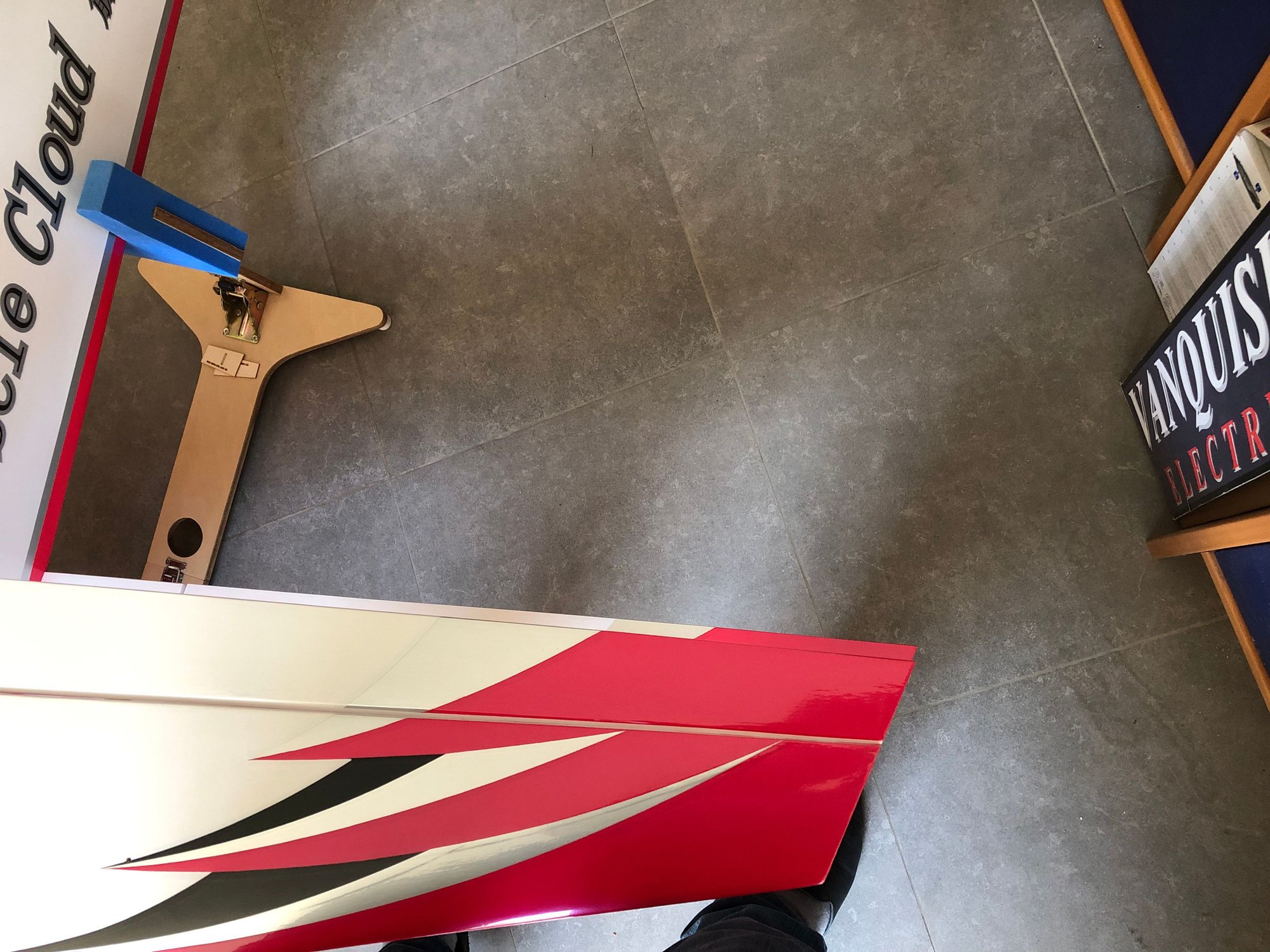
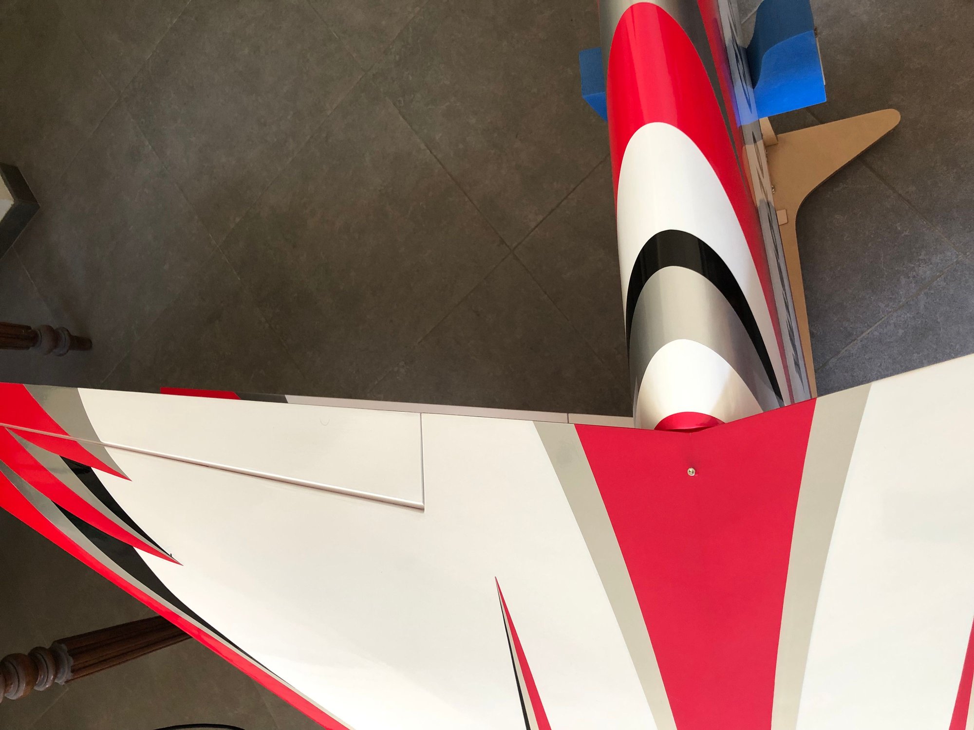
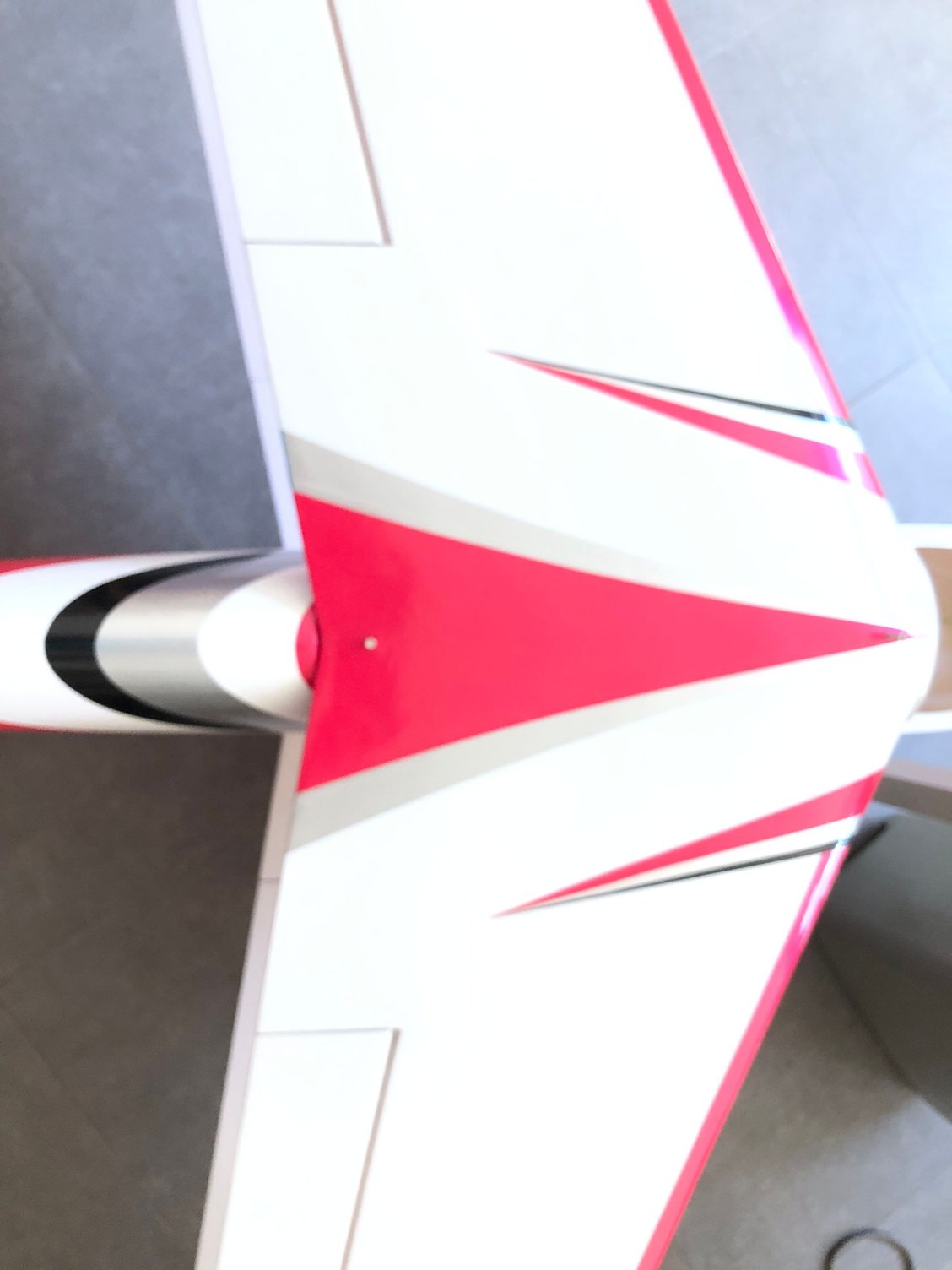

With just 2 screws to position the wing perfectly aligned with the bottom wing and centered on the fuselage, this operation take time.
I decided to remove the blind nuts already installed in the fuselage for the bottom wing, and to use Heavy Duty 3 mm MP JETS.
With the wing positioned, I glued in place the inserts with 30 mn ZAP Epoxy.
For the top wing I drilled the top fuselage with the wing in position with a 3 mm bit through the wing, and had a small decalage in the holes already pre drilled.
Preparing the wings for the struts is easy when you know the location ...
Wings done 😎😎
04-14-2025 | 10:59 PM
#19
Thread Starter
My Feedback: (1)
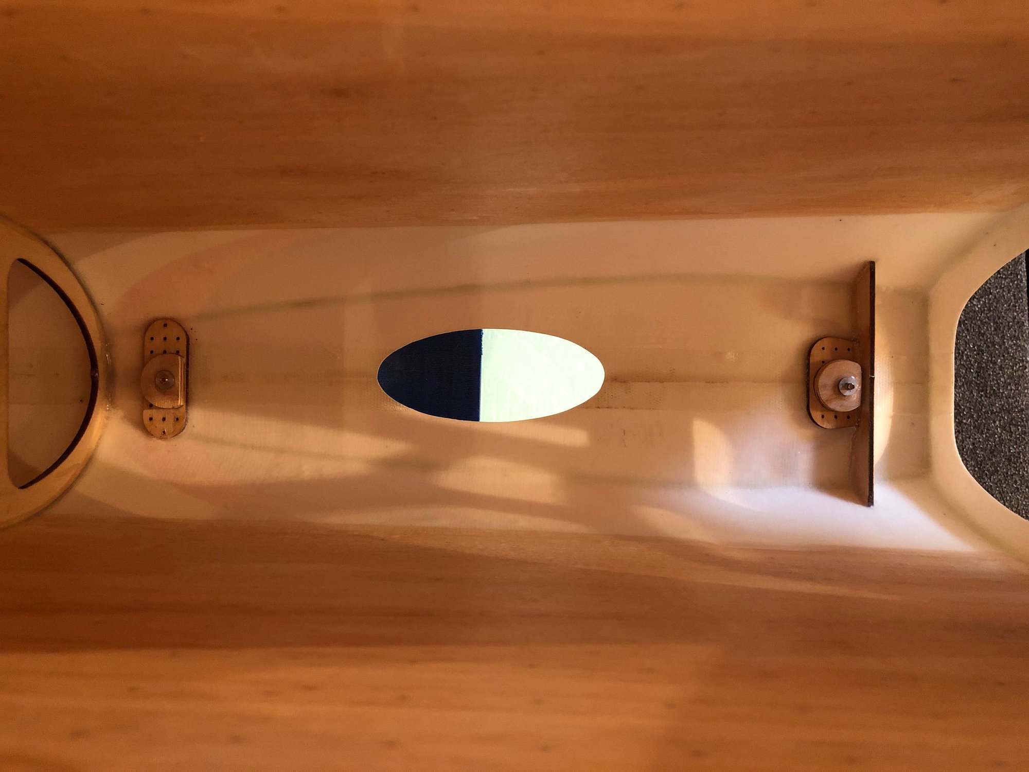
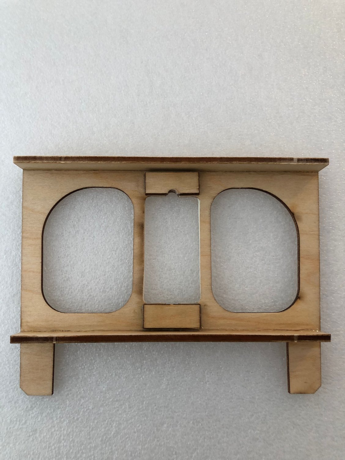
Rudder servo tray installation
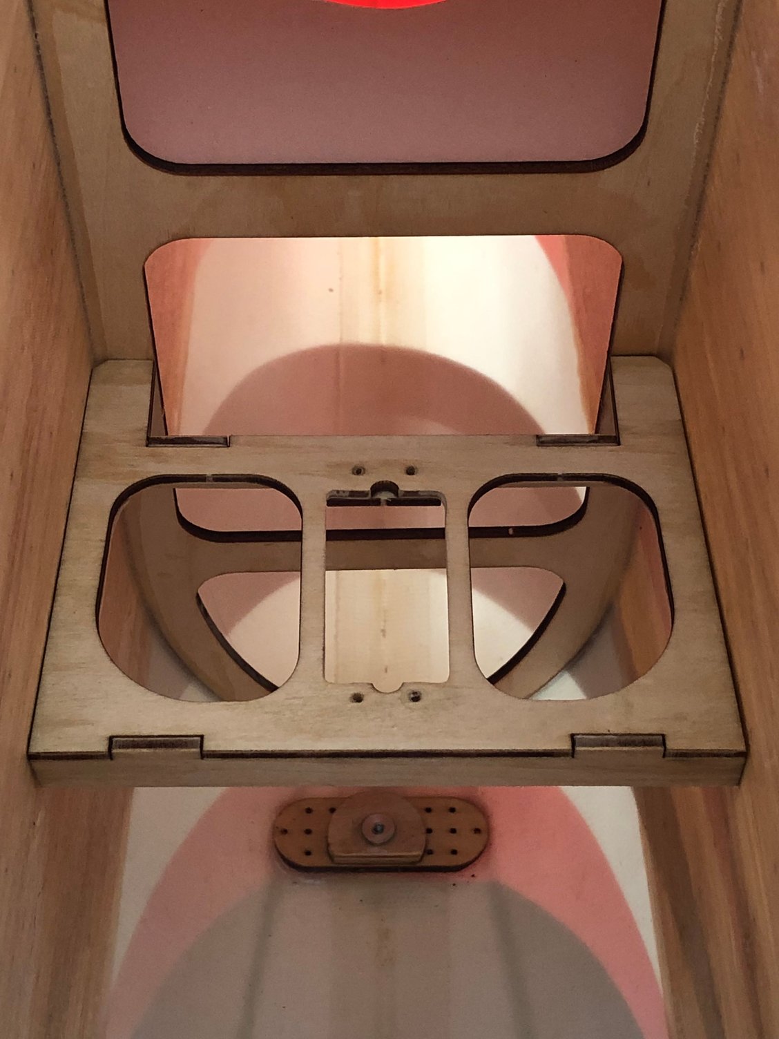
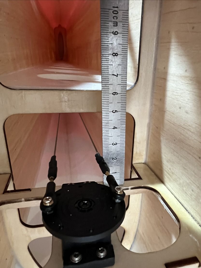
Initially the rudder servo was installed at the rear of the fuselage on the prototype , but now is moved forward for CG purpose.
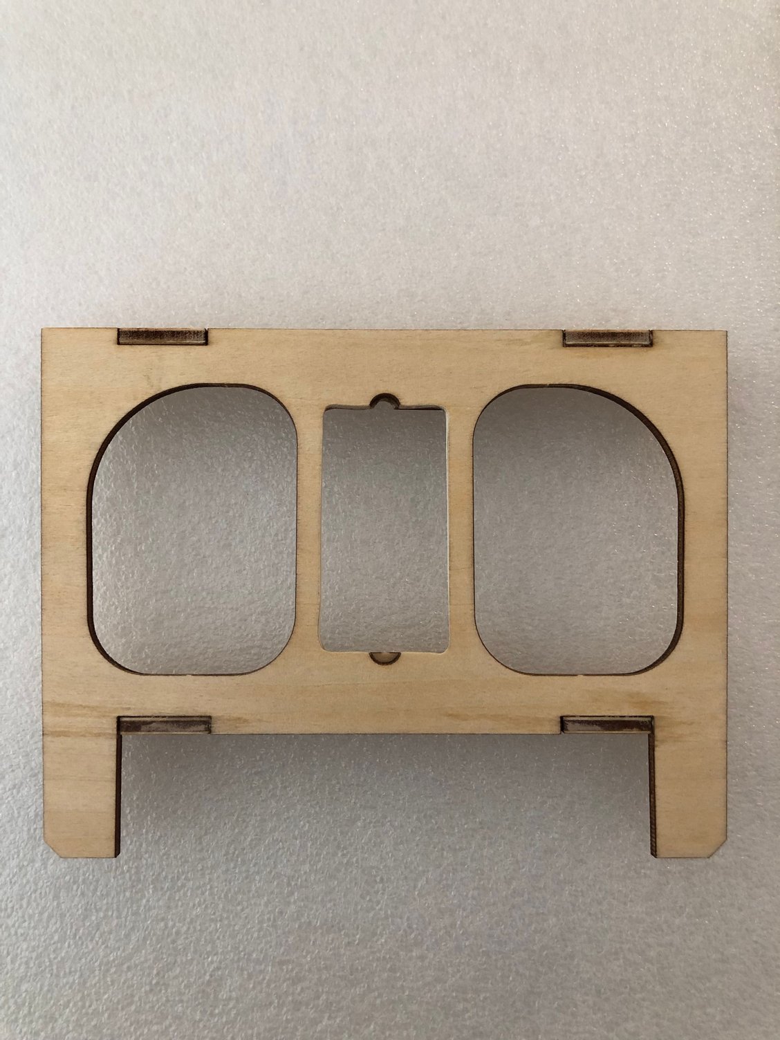
BJ give some informations about the servo tray location and the holes exit in the fuselage for the cables.
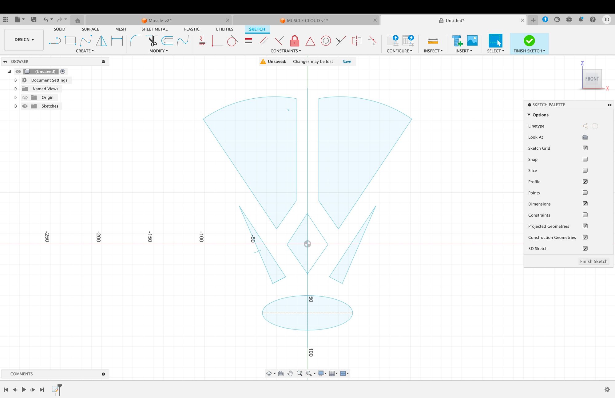
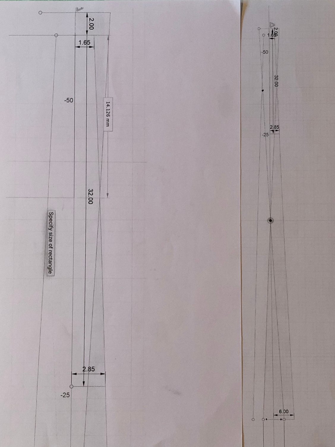
I checked the exact location, both by empiric method and Fusion 360, and it's really close from the location given by the template coming with the kit.
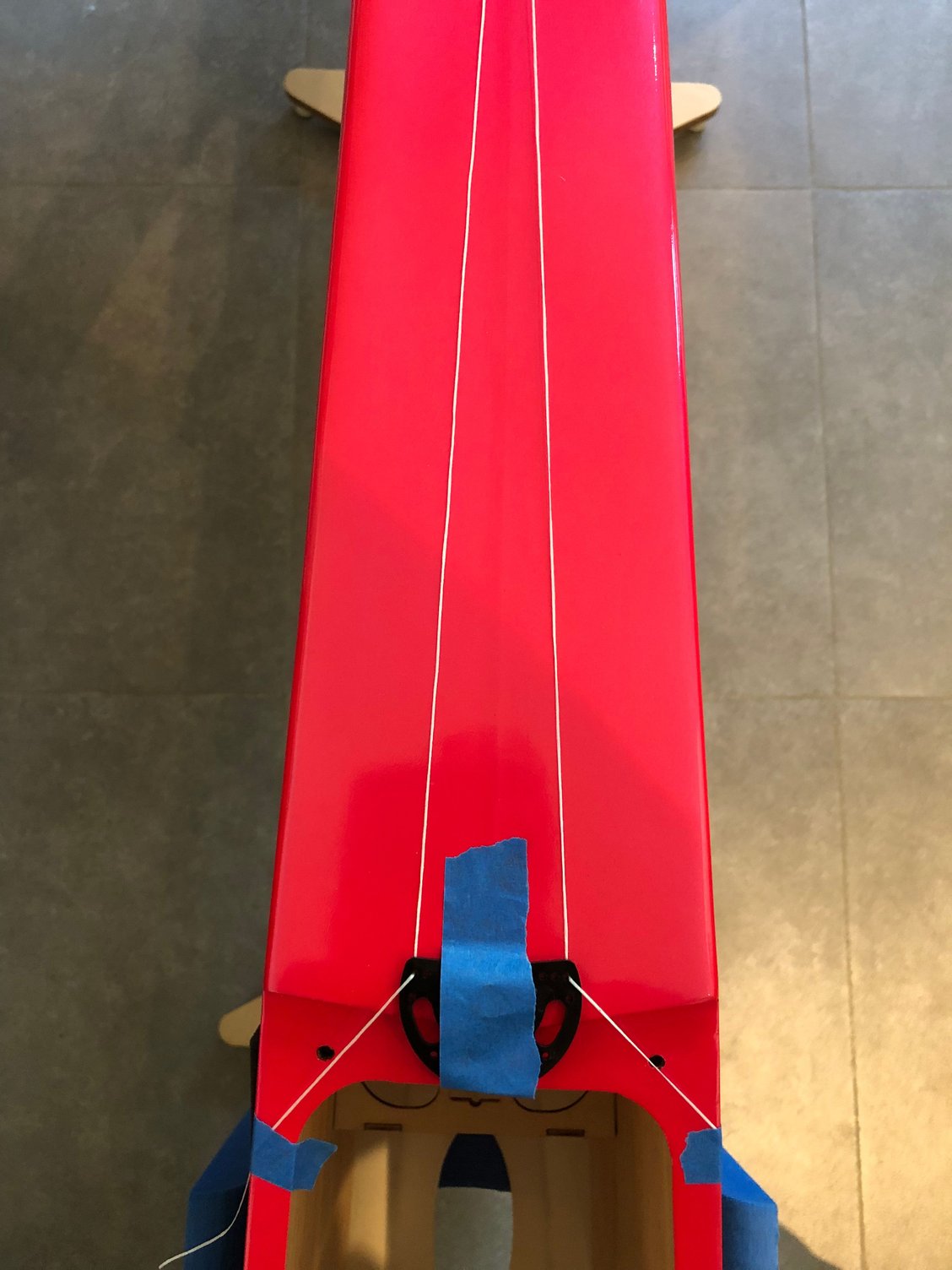
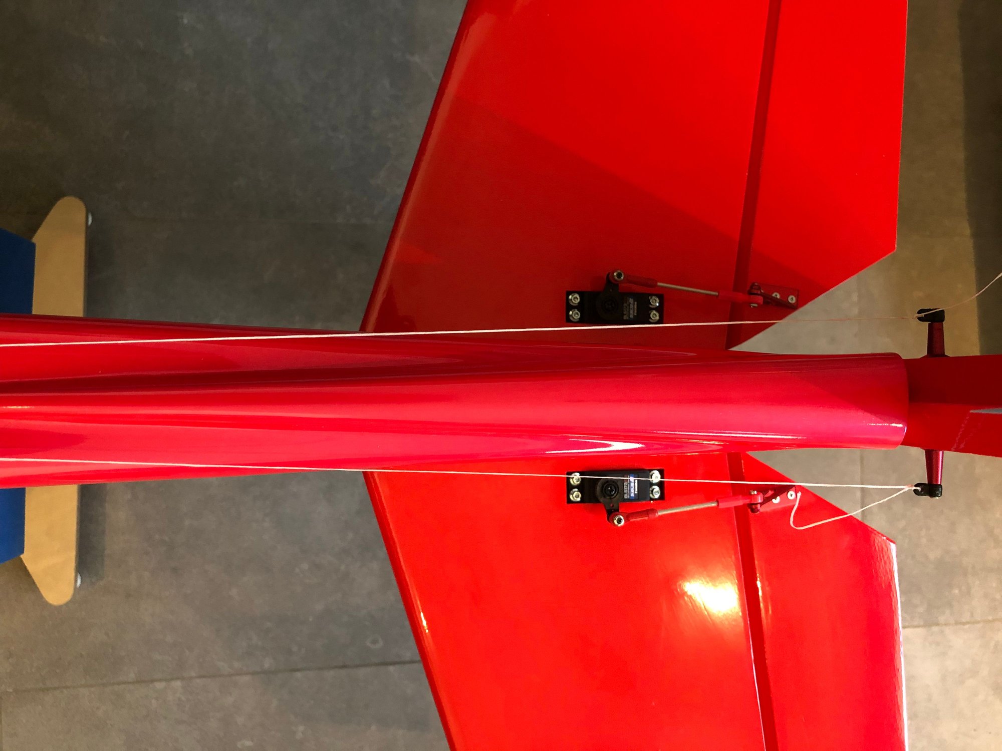
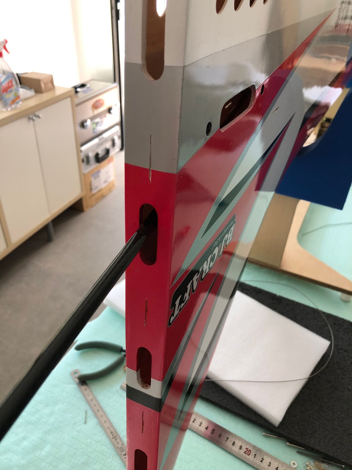
The problem is to have the cables running straight, and you need to drill two holes in the rear tail former.
The location of the tray in the fuselage is mentioned on BJ picture.
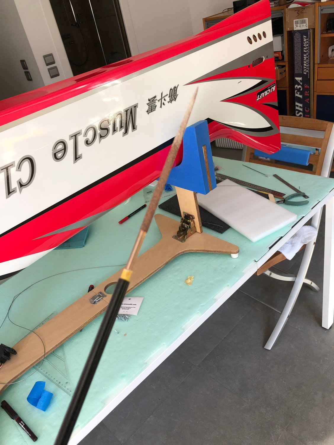
Before gluing in place the rudder, I installed a paper tube for the elevator wires.

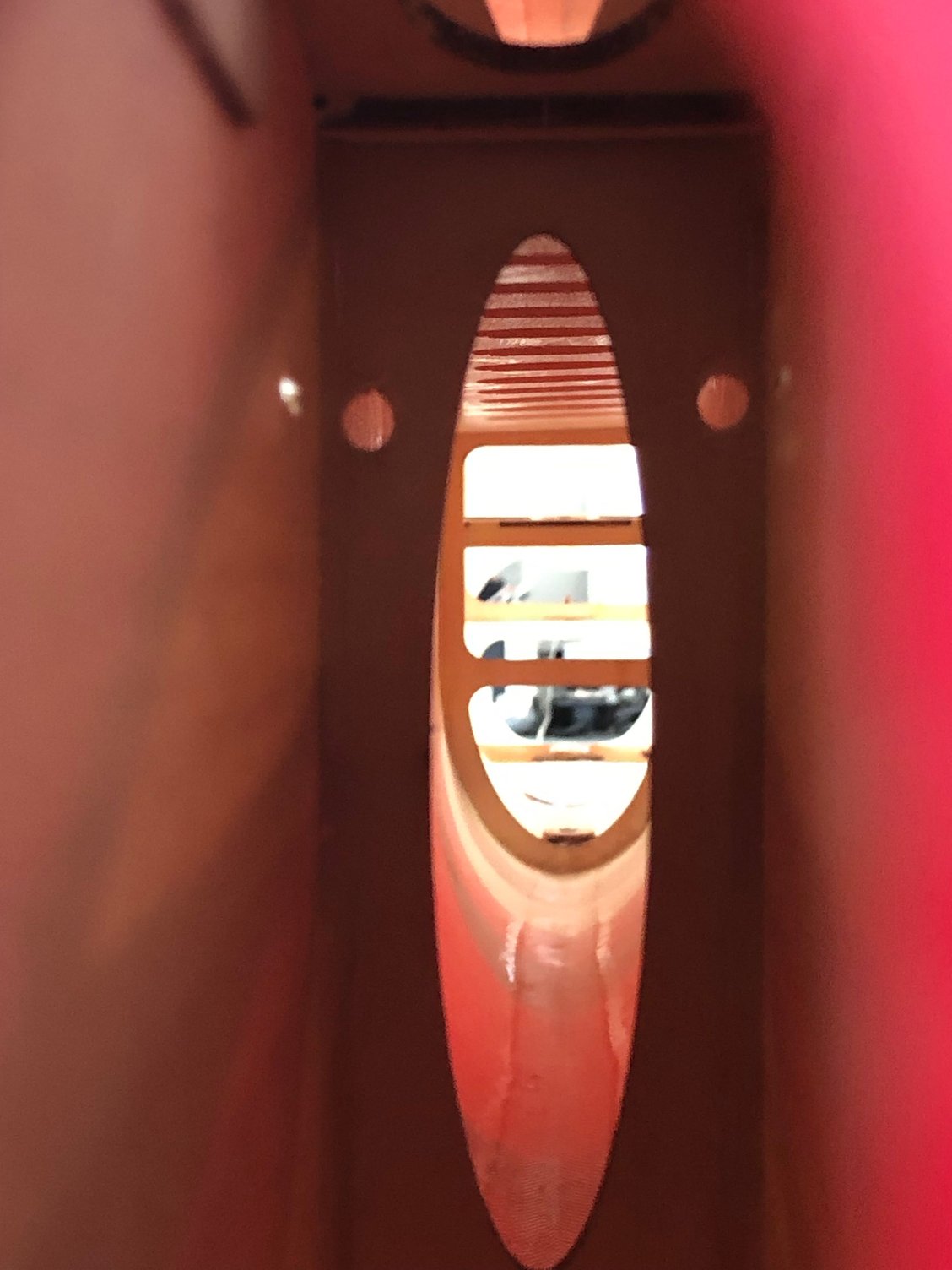
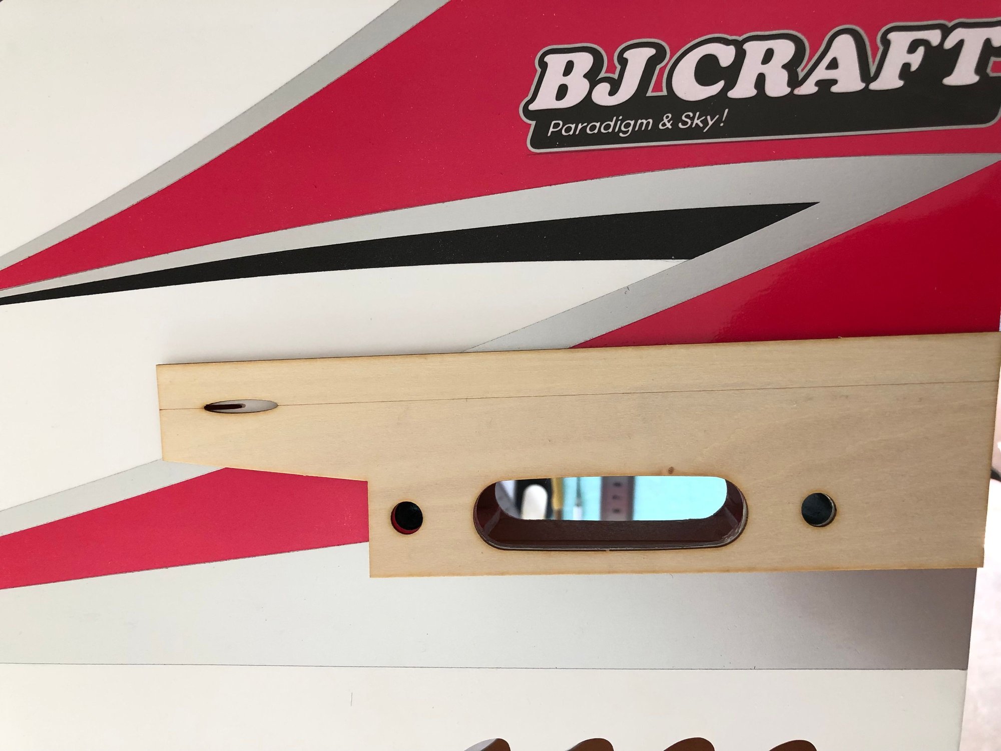

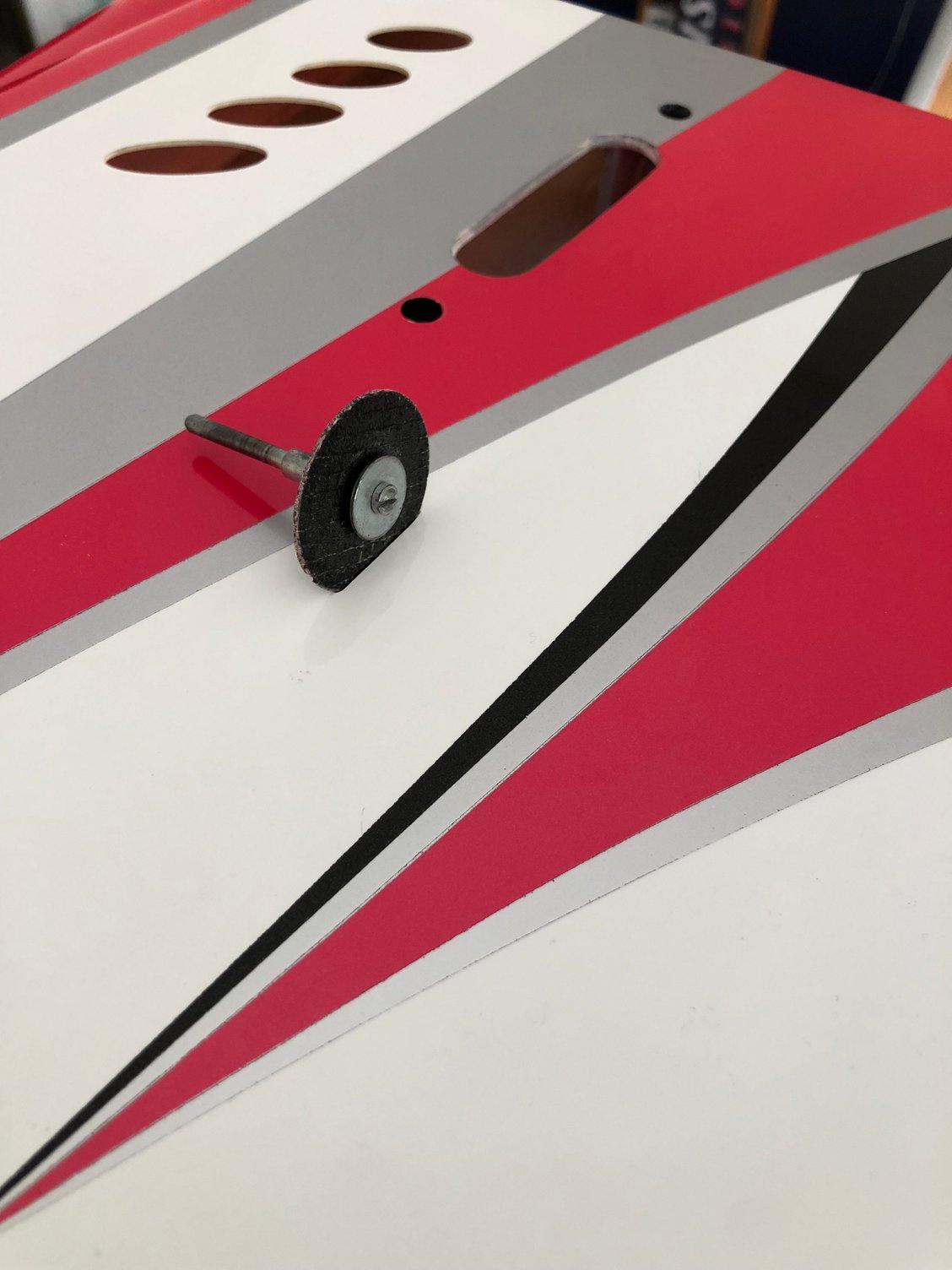

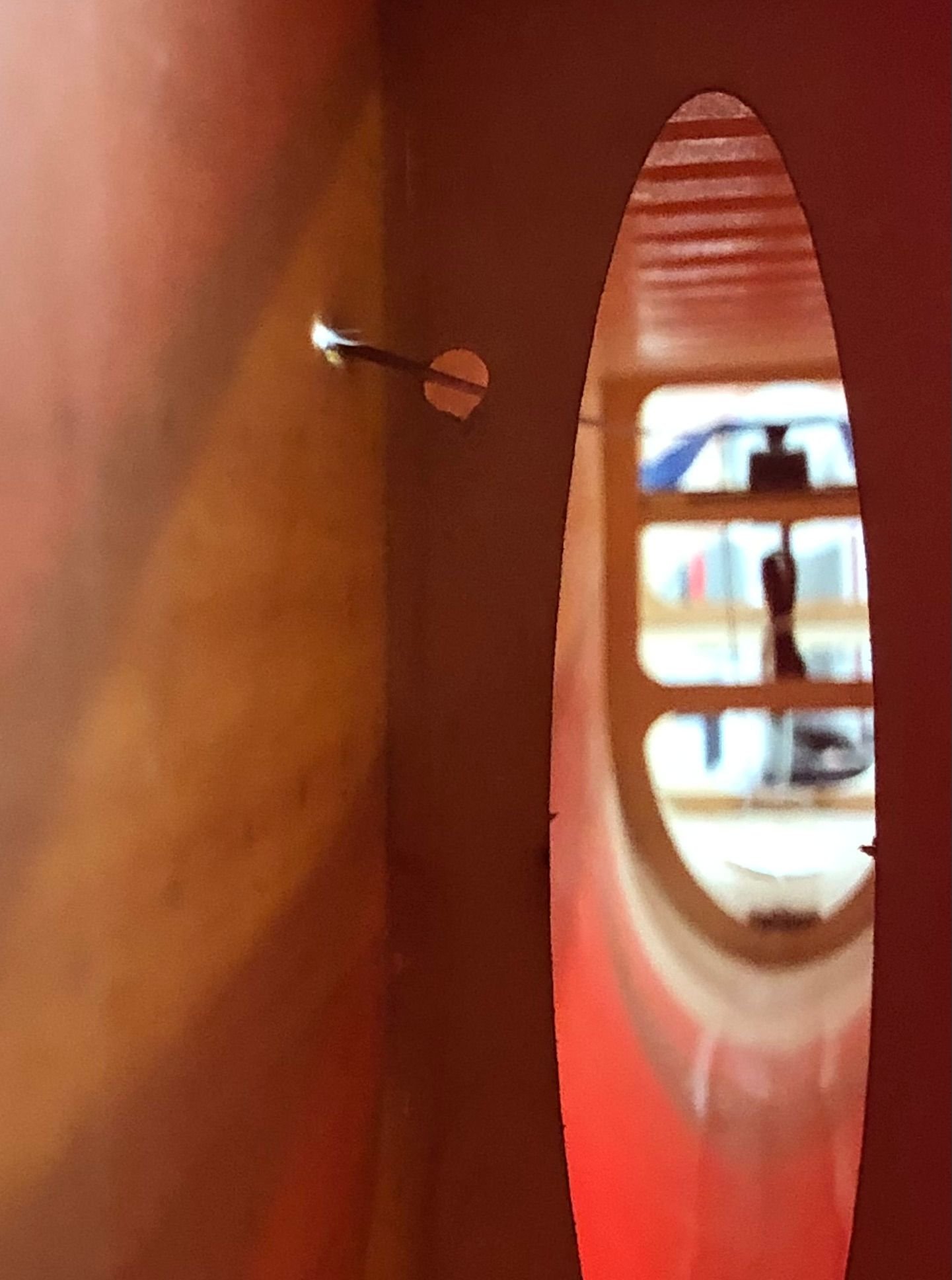
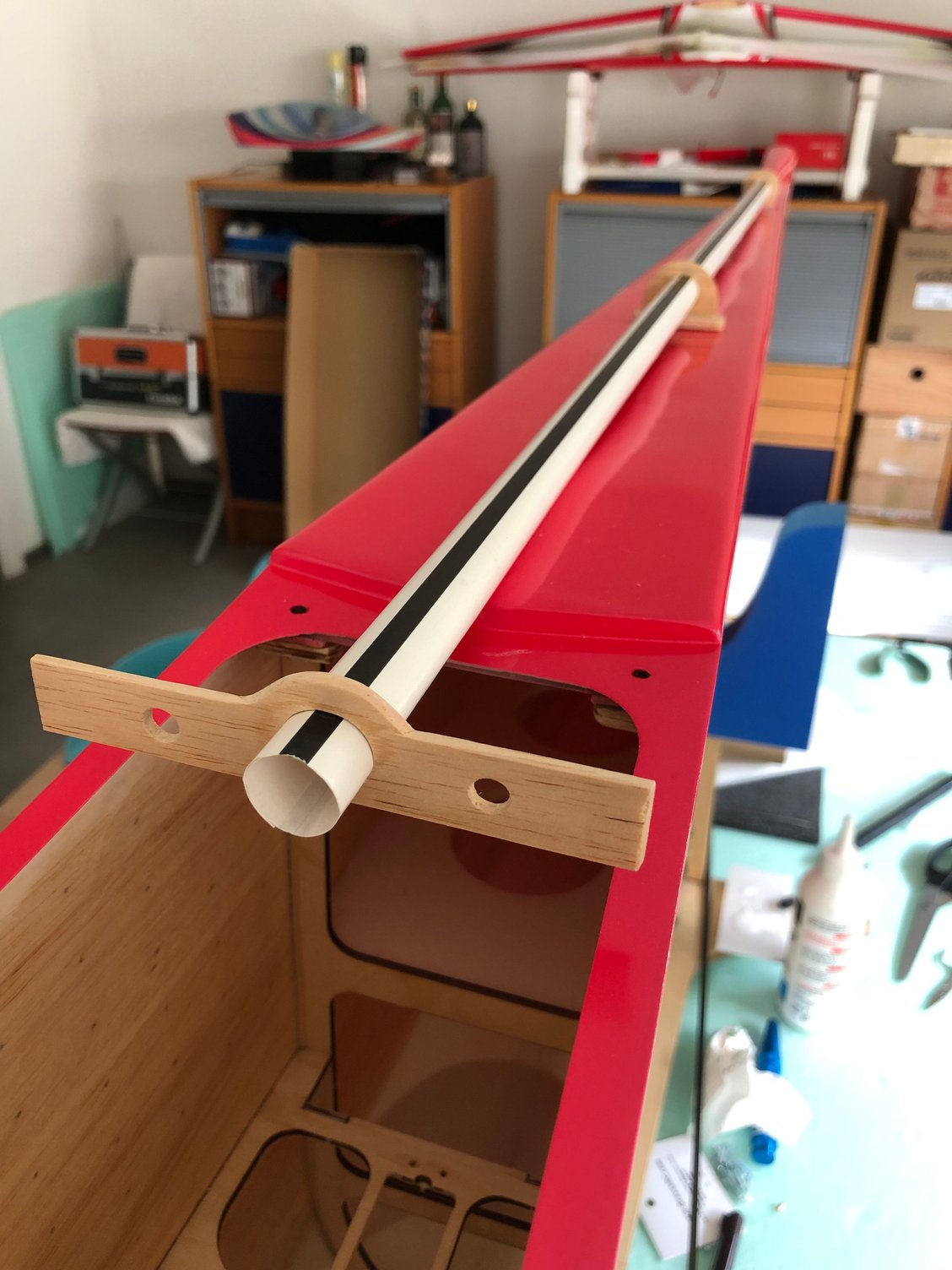
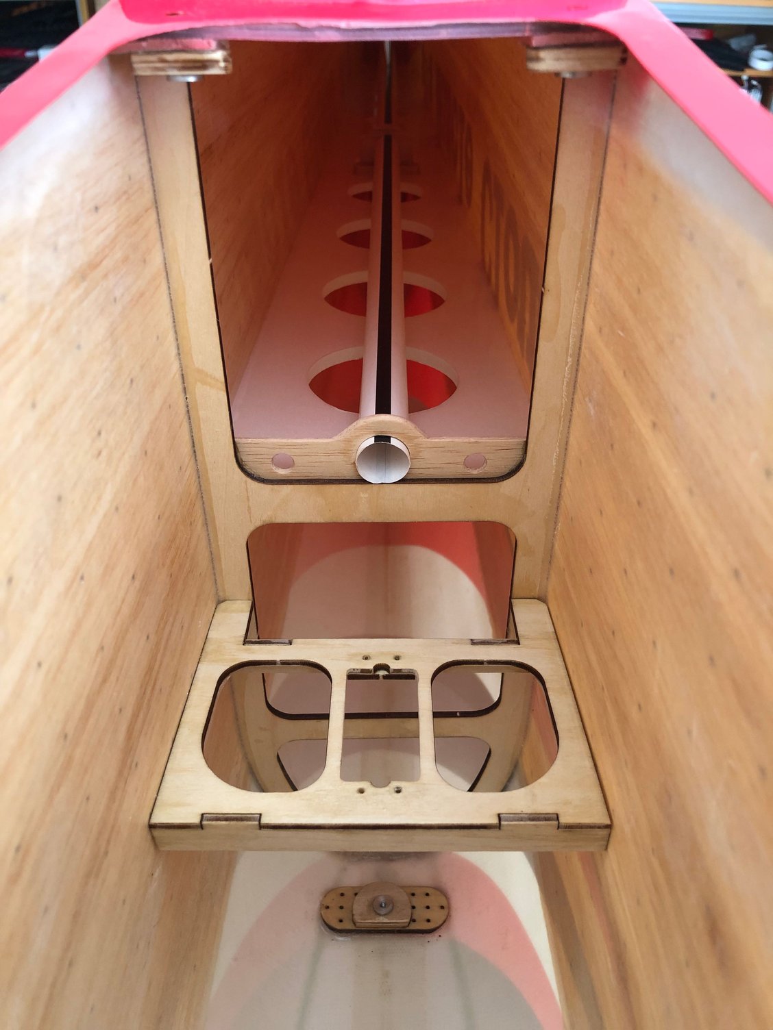
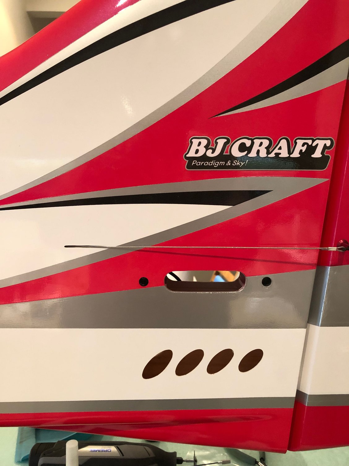
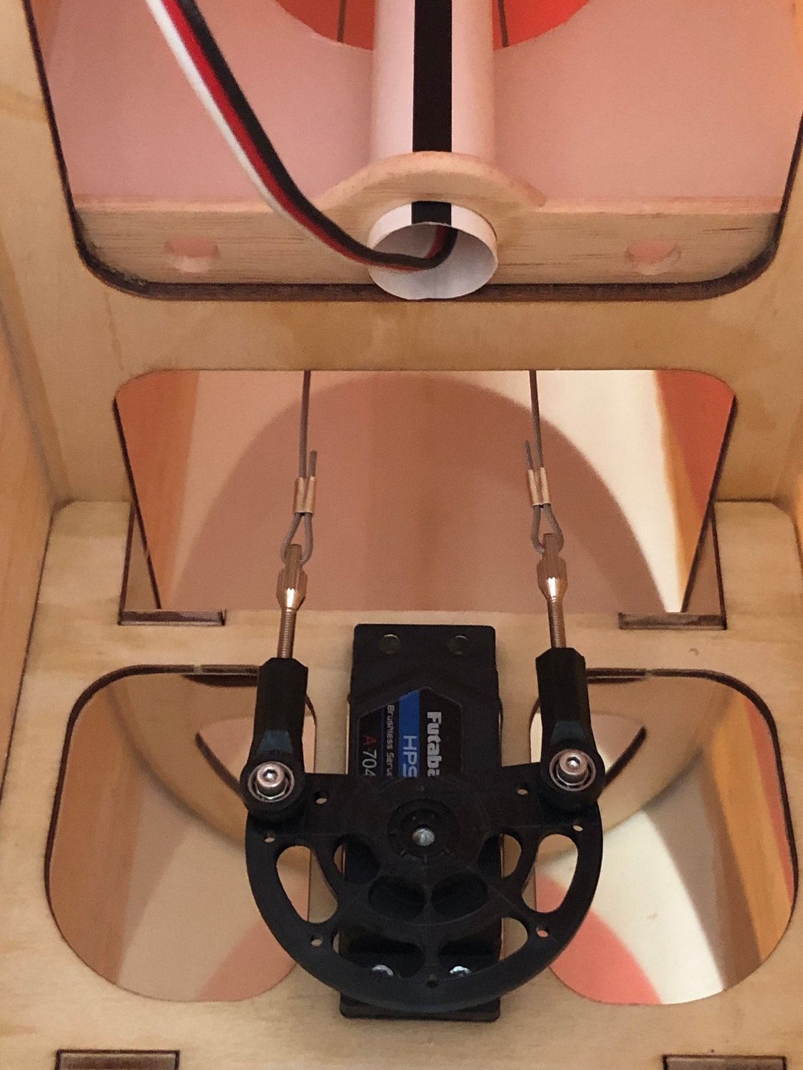
Initially the rudder servo was installed at the rear of the fuselage on the prototype , but now is moved forward for CG purpose.
BJ give some informations about the servo tray location and the holes exit in the fuselage for the cables.
I checked the exact location, both by empiric method and Fusion 360, and it's really close from the location given by the template coming with the kit.
The problem is to have the cables running straight, and you need to drill two holes in the rear tail former.
The location of the tray in the fuselage is mentioned on BJ picture.
Before gluing in place the rudder, I installed a paper tube for the elevator wires.
Last edited by J-P; 04-14-2025 at 11:20 PM.
The following users liked this post:
rcprecision (04-17-2025)
04-28-2025 | 11:37 PM
#20
Thread Starter
My Feedback: (1)
Engine mount installation
I took time to get all the parts to complete the build.
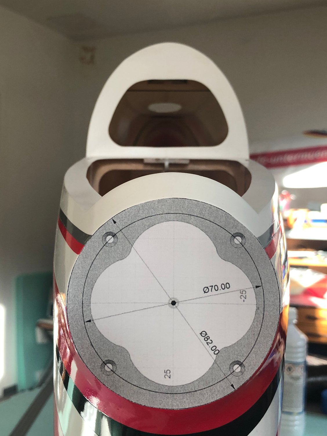
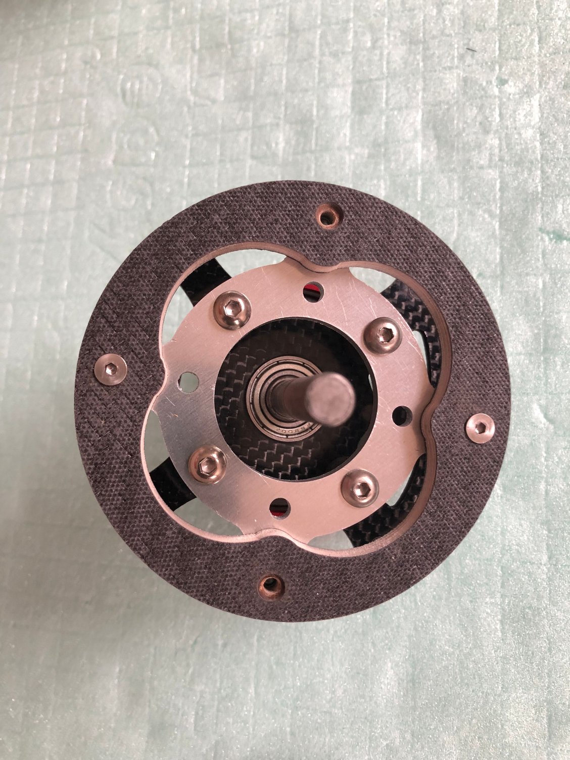
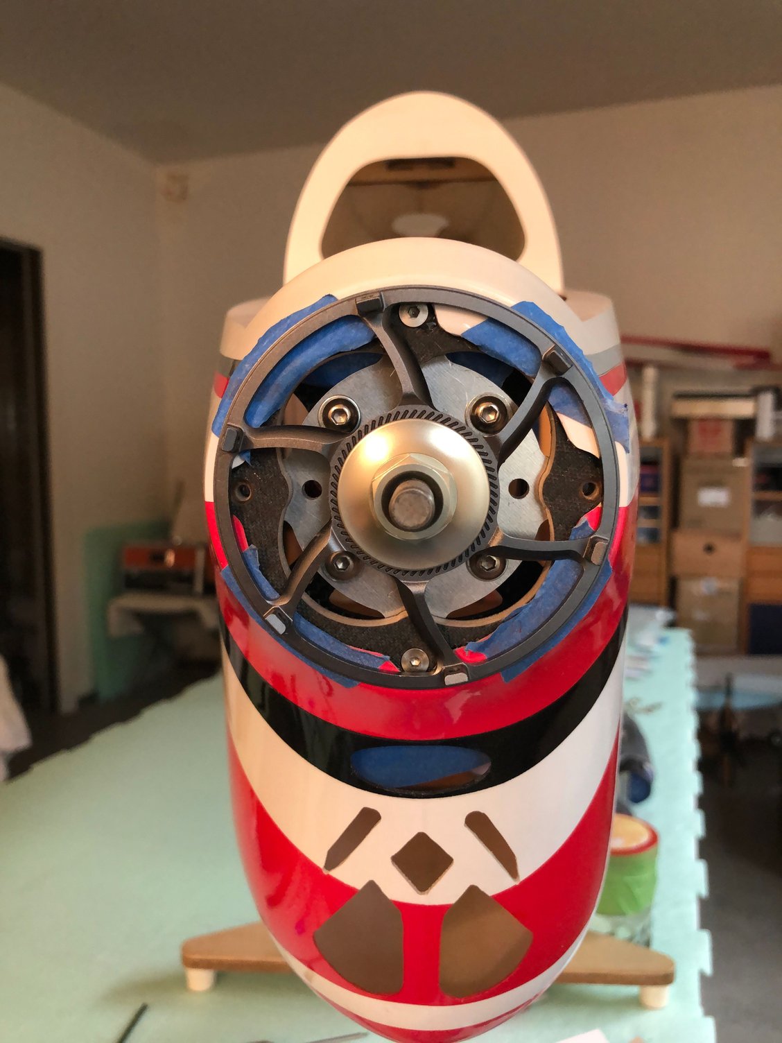
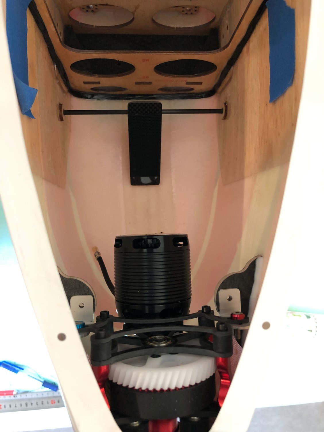
To have the ADVERRUN V3 perfectly installed and flushed with the nose of the fuselage, the front mount must be 6 mm thickness.
This part was done CNC by Jean Pierre ZARDINI - ZN LINE -
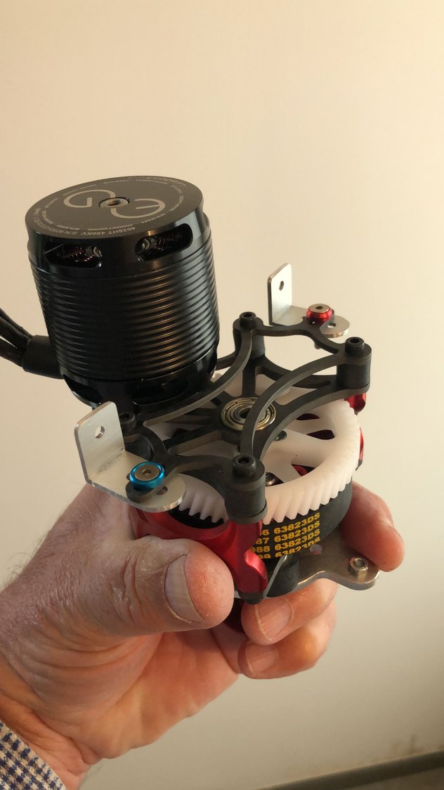
I used 10 mm front rubber dampers instead of the stock ones, and the ADVERRUN contra mount.
Note that the length of these rubber dampers is 2 mm longer.
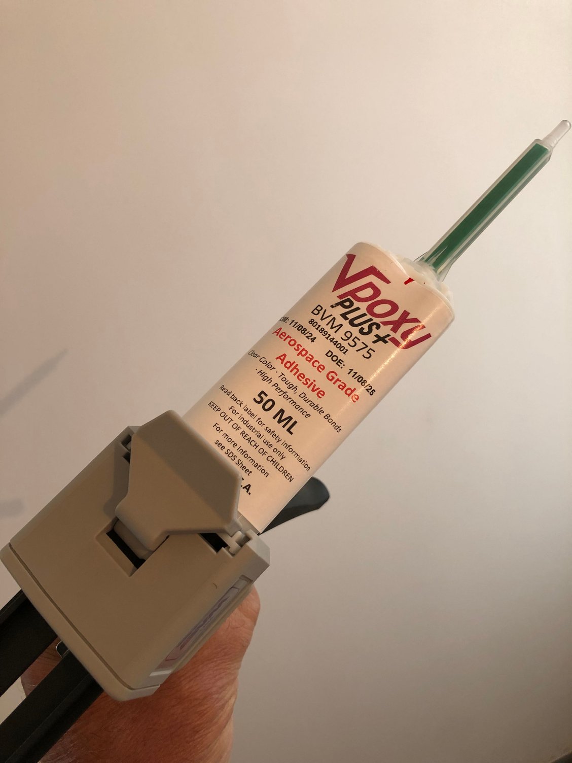
A single drive ADVERRUN gear helped to position and center the front mount before gluing in place with BVM Vpoxy Plus+.
The front part of the fuselage is just 82 mm, as well as the spinner diameter, so some accuracy is needed.
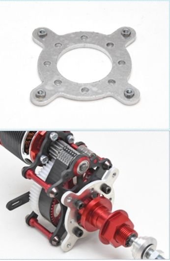
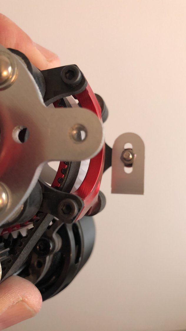
As it's narrower than the one of the LEADER or EPILOGUE, I adapted the rear part of the mount installation, using a NISHIOKA part I had.
This installation will allow for a fine tuning of the down or side thrust necessary.




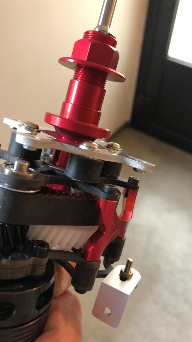
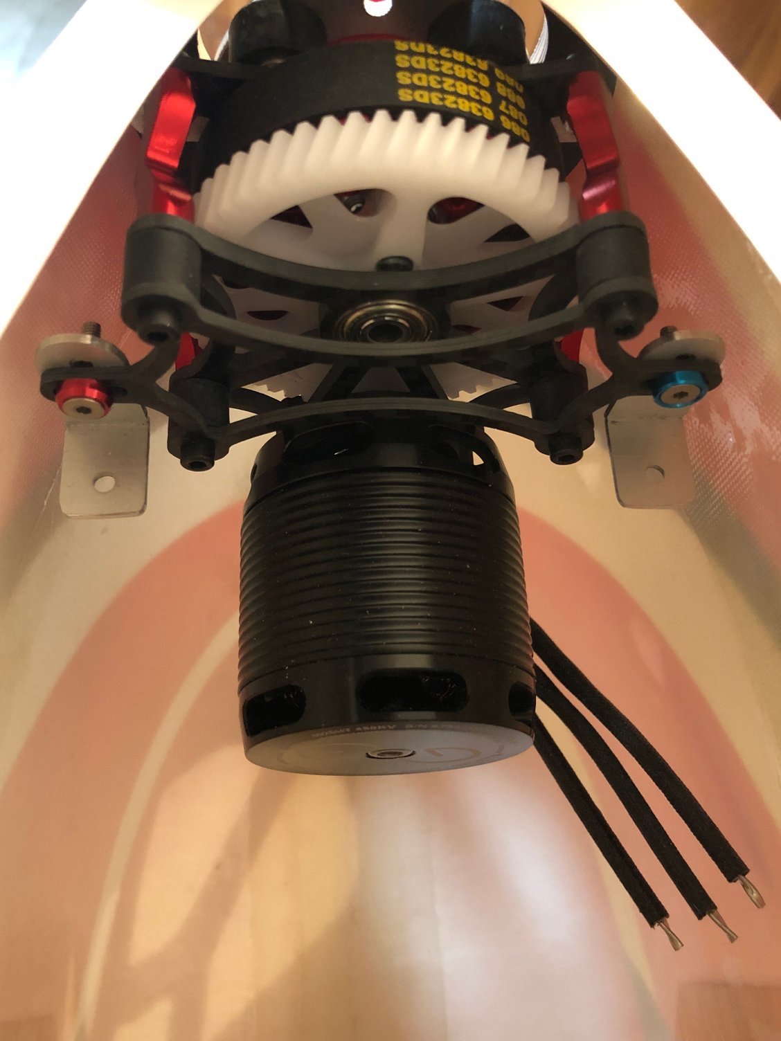

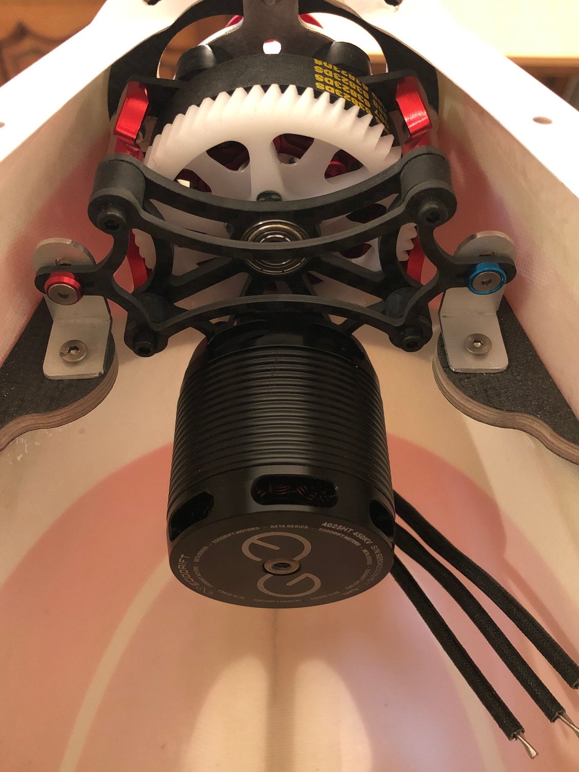
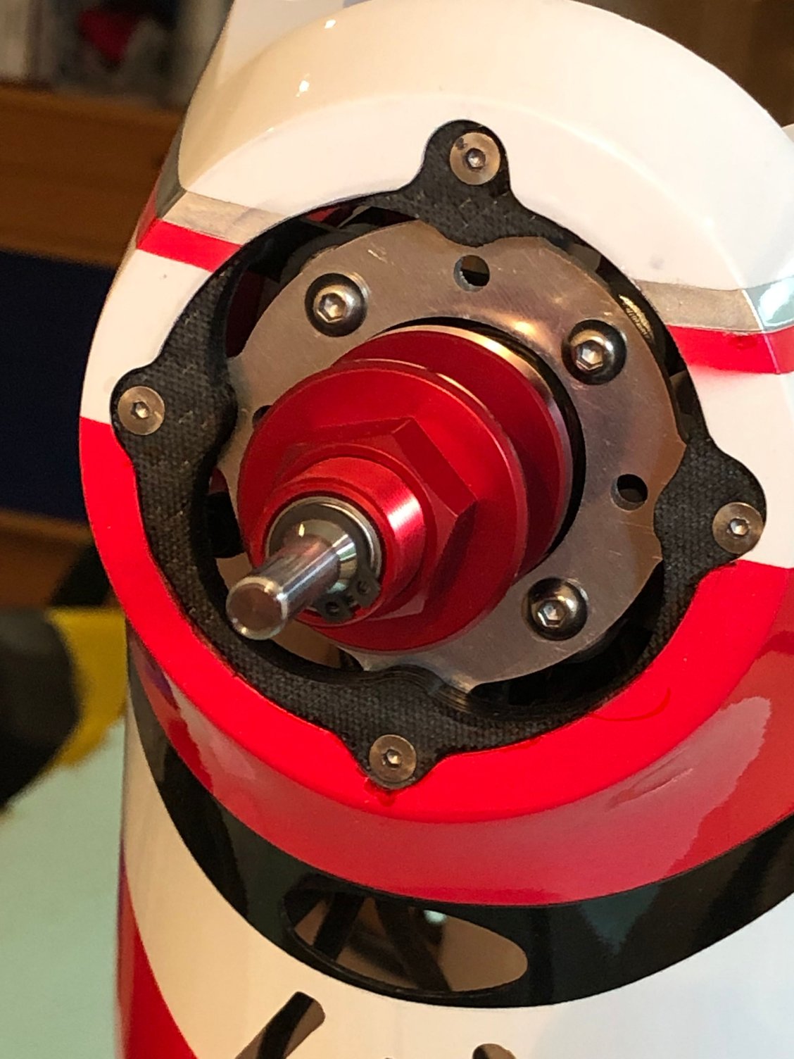
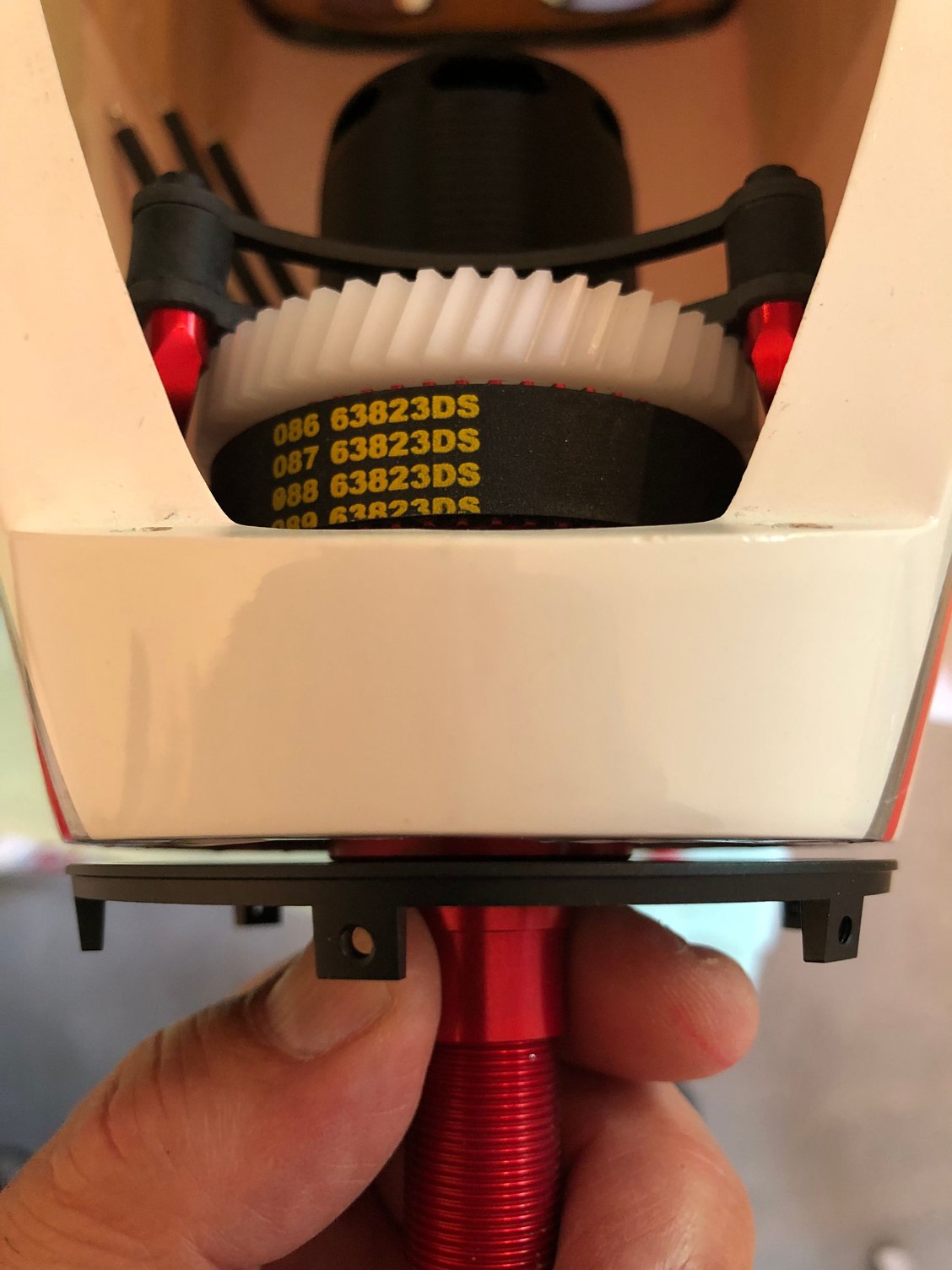
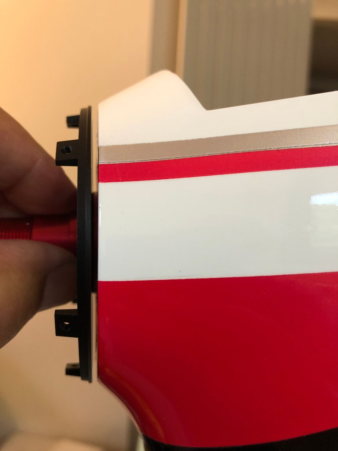
I took time to get all the parts to complete the build.
To have the ADVERRUN V3 perfectly installed and flushed with the nose of the fuselage, the front mount must be 6 mm thickness.
This part was done CNC by Jean Pierre ZARDINI - ZN LINE -
I used 10 mm front rubber dampers instead of the stock ones, and the ADVERRUN contra mount.
Note that the length of these rubber dampers is 2 mm longer.
A single drive ADVERRUN gear helped to position and center the front mount before gluing in place with BVM Vpoxy Plus+.
The front part of the fuselage is just 82 mm, as well as the spinner diameter, so some accuracy is needed.
As it's narrower than the one of the LEADER or EPILOGUE, I adapted the rear part of the mount installation, using a NISHIOKA part I had.
This installation will allow for a fine tuning of the down or side thrust necessary.
The following 2 users liked this post by J-P:
rcprecision (04-29-2025),
wattsup (04-29-2025)
05-04-2025 | 06:53 AM
#21
Thread Starter
My Feedback: (1)
Radio and ESC installation
As I’m waiting for the landing gear to return from painting, I can’t check the CG for positioning the battery tray.
So I started the FUTABA R7308SB & R9001SB RX installation.
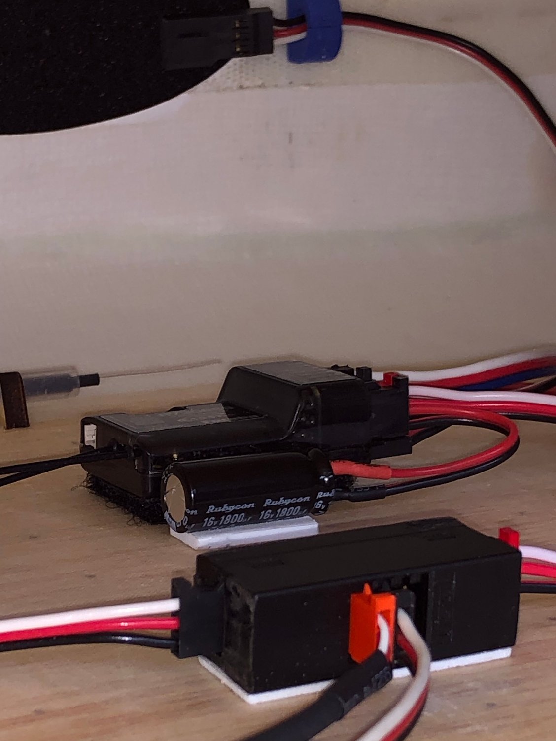
With an A 704 and four A 600 FUTABA servos, I used a capacitor.
A small plate behind the canopy accommodate the Digiswitch V2, a 500 mah RX battery and an Ultraguard.
For the ESC, I'll start with my favorite, the D3 , and then will give a try to the VLV, interested to see if any difference in performance, and of course by the integrated telemetry.
Installation is in the airflow reclined at 45 °
Next step will be the ldg installation, then the location of the battery tray to achieve the 220 mm CG position recommended by BJ.
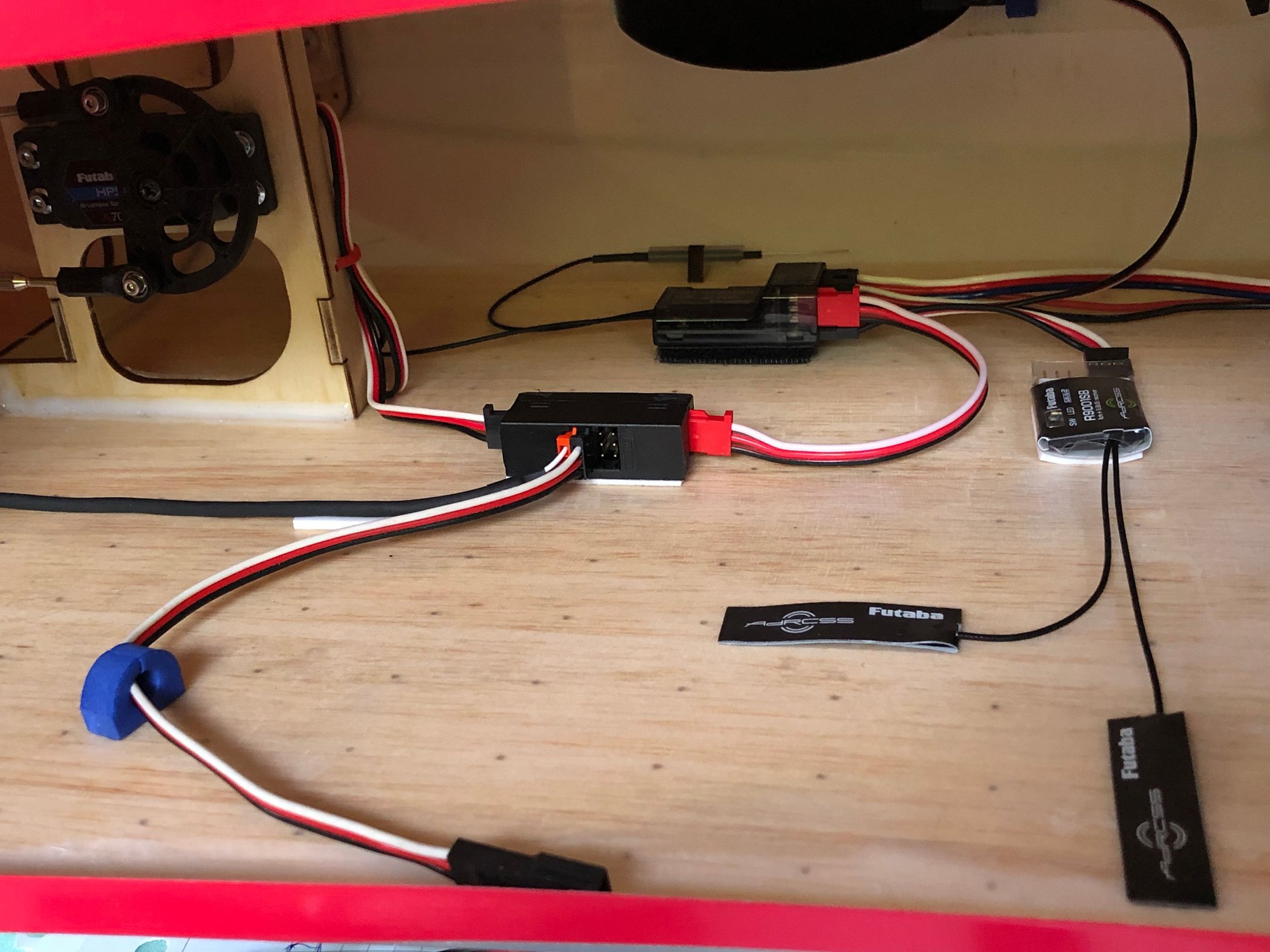
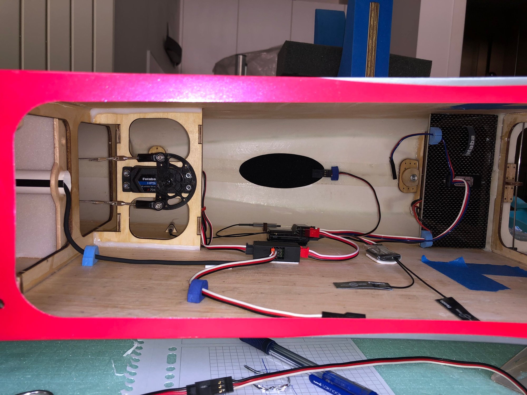
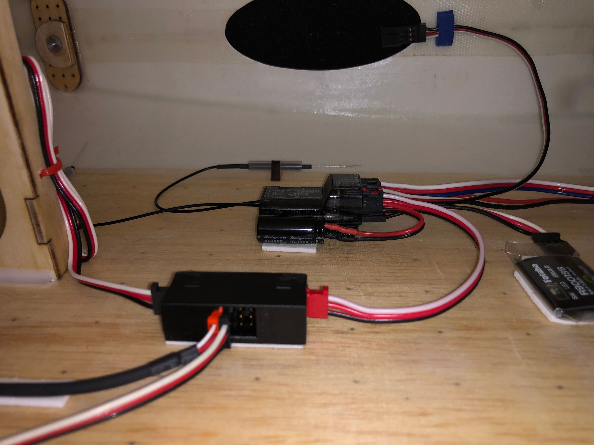
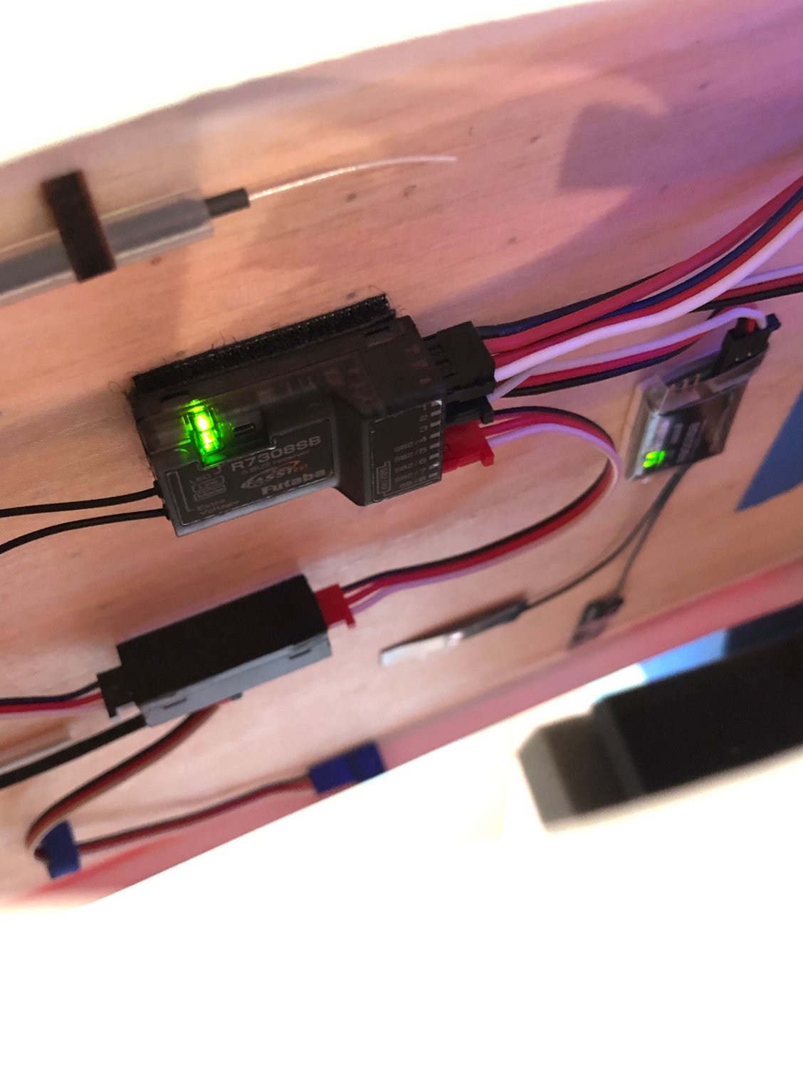
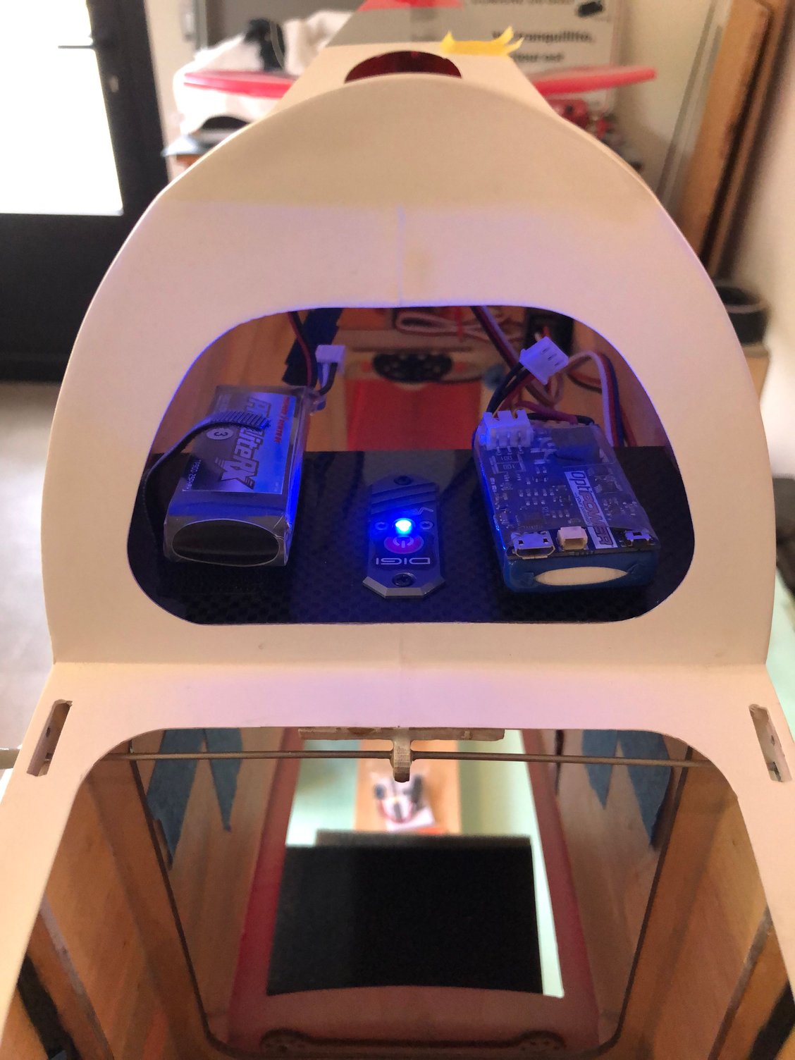

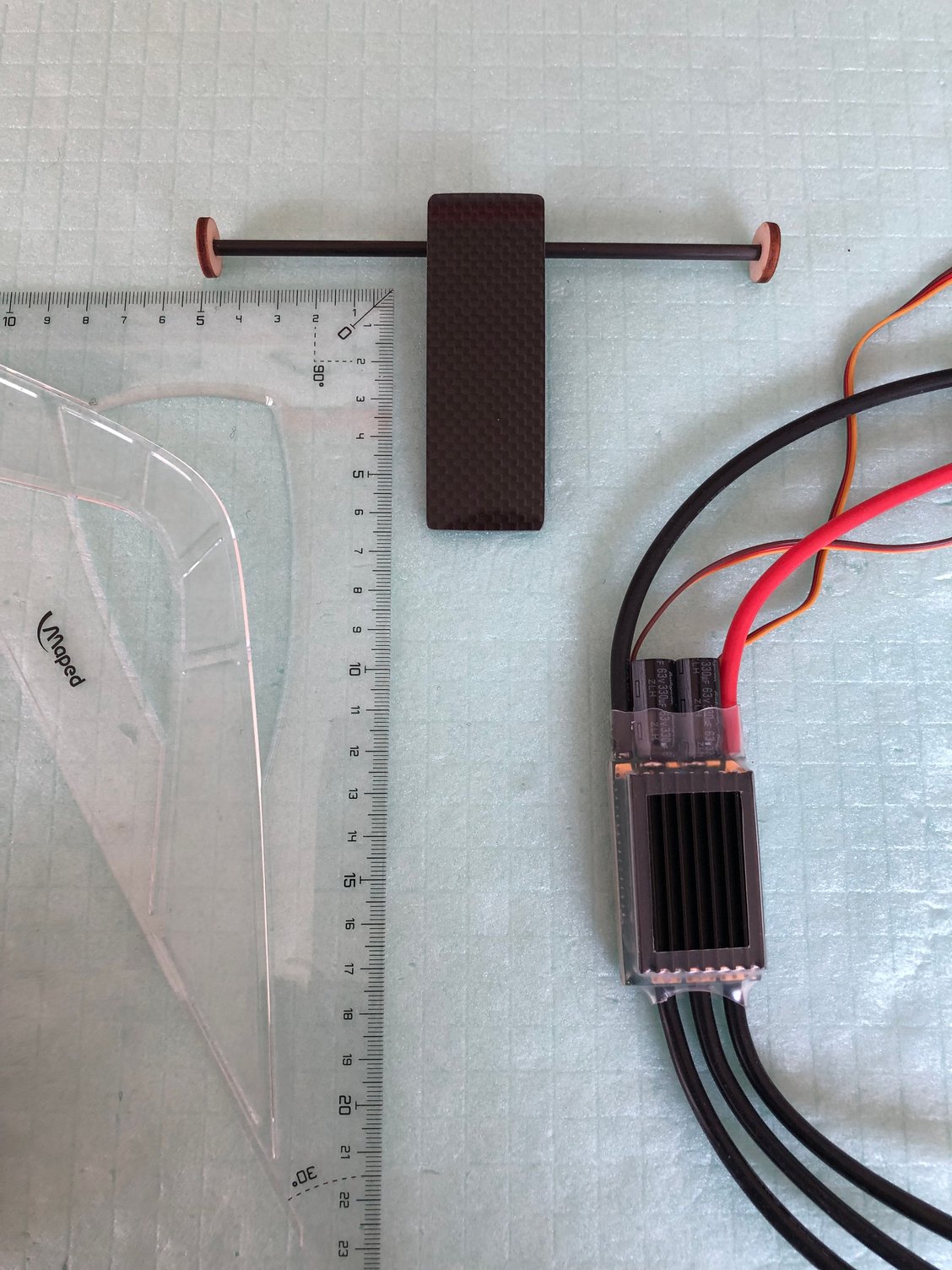
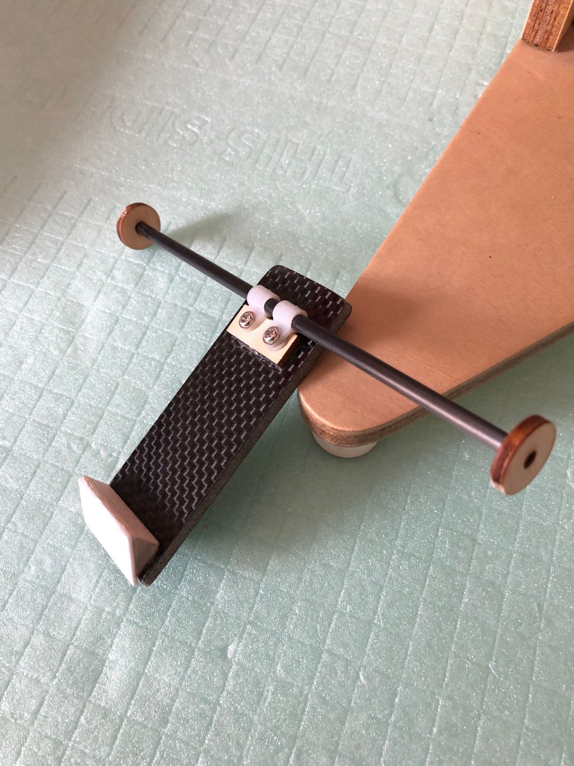
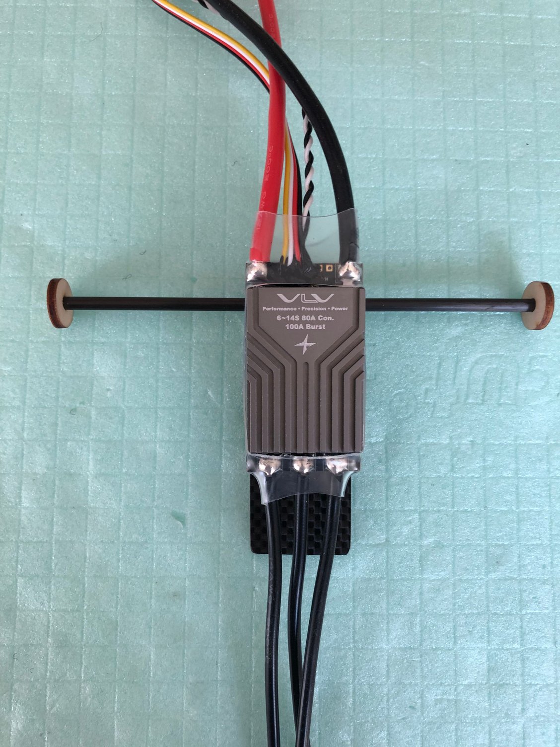
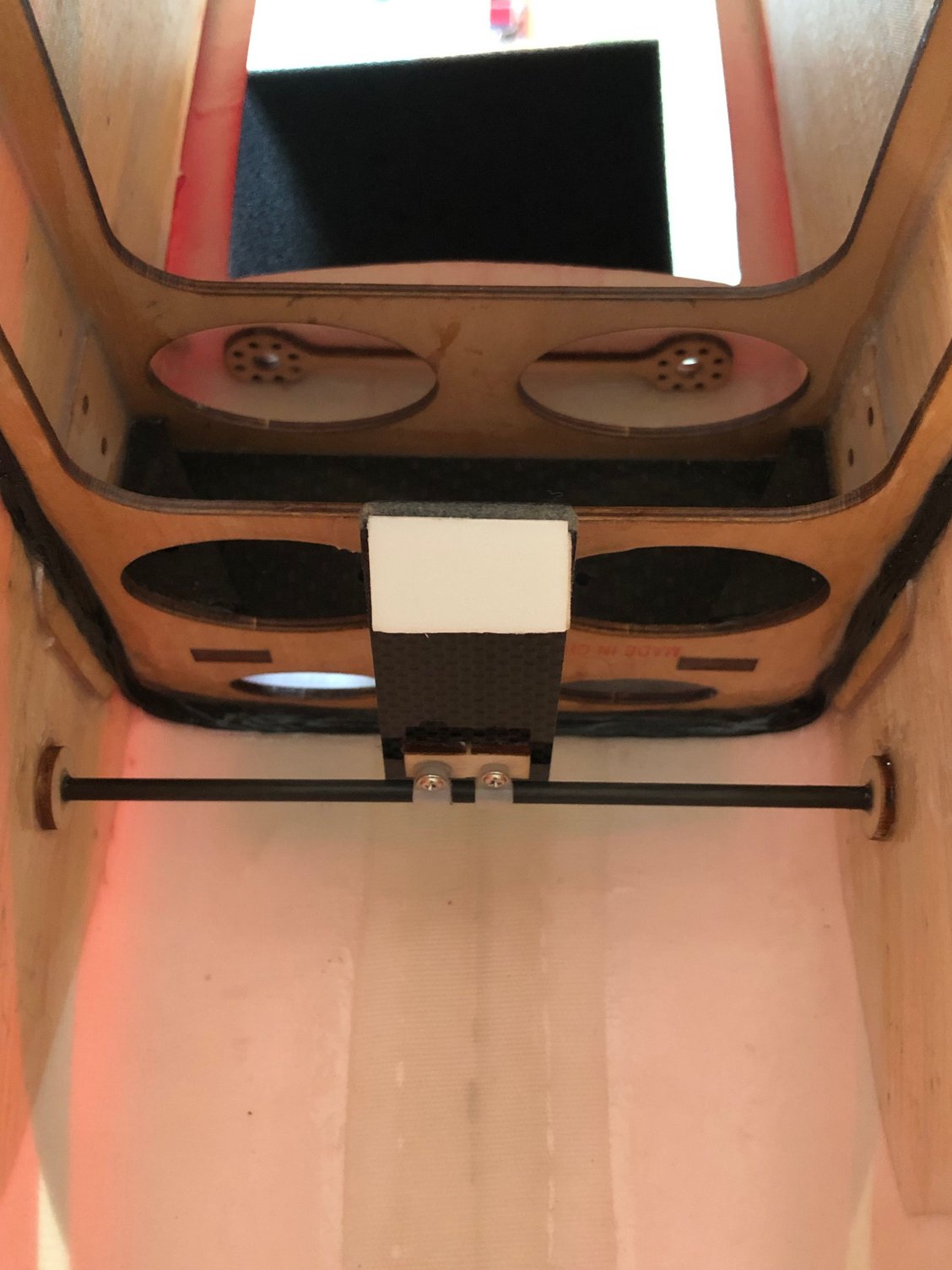
As I’m waiting for the landing gear to return from painting, I can’t check the CG for positioning the battery tray.
So I started the FUTABA R7308SB & R9001SB RX installation.
With an A 704 and four A 600 FUTABA servos, I used a capacitor.
A small plate behind the canopy accommodate the Digiswitch V2, a 500 mah RX battery and an Ultraguard.
For the ESC, I'll start with my favorite, the D3 , and then will give a try to the VLV, interested to see if any difference in performance, and of course by the integrated telemetry.
Installation is in the airflow reclined at 45 °
Next step will be the ldg installation, then the location of the battery tray to achieve the 220 mm CG position recommended by BJ.
The following 2 users liked this post by J-P:
rcprecision (05-05-2025),
wattsup (05-04-2025)
06-13-2025 | 03:42 AM
#22
Thread Starter
My Feedback: (1)
Location of the battery tray
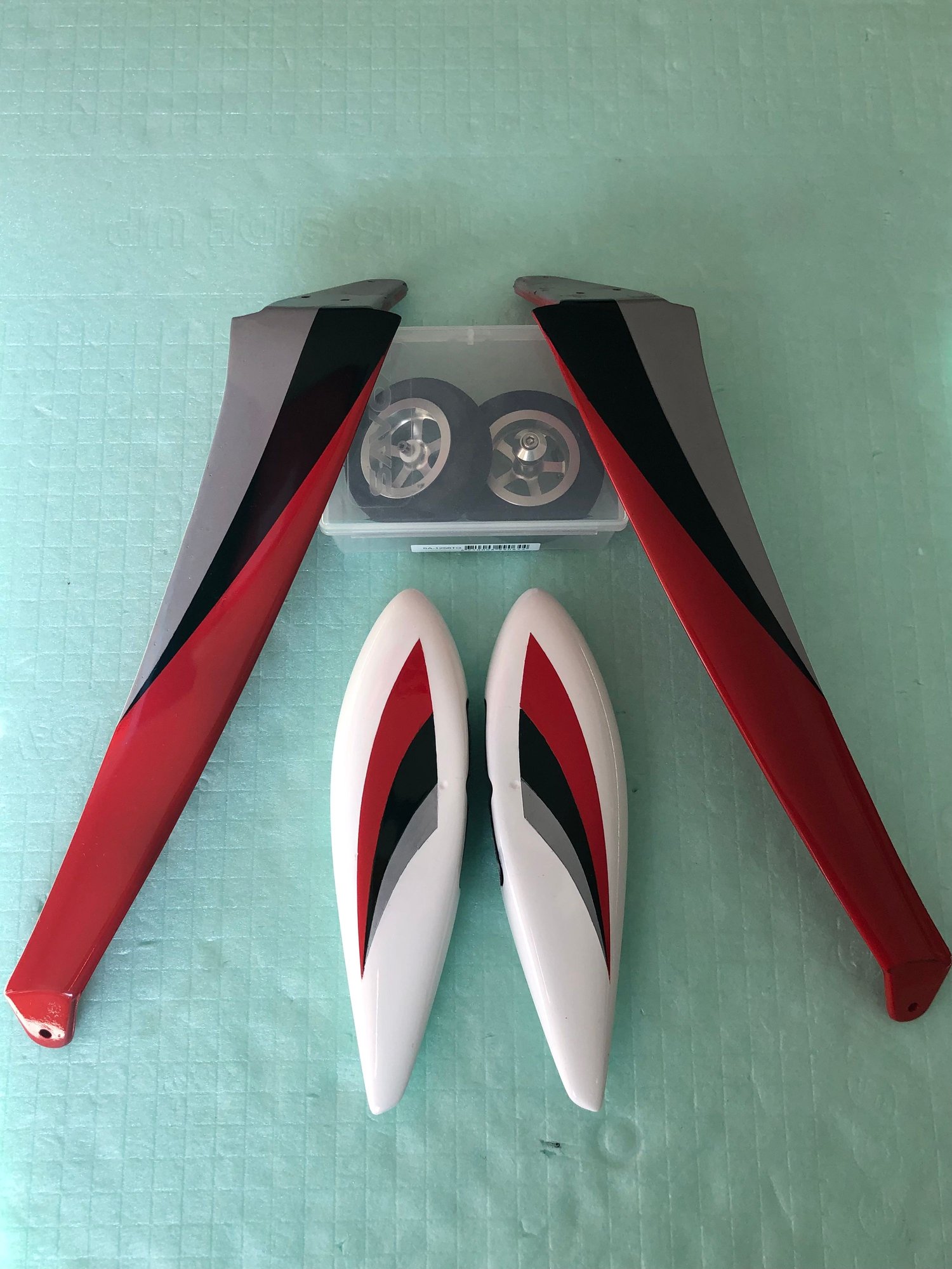
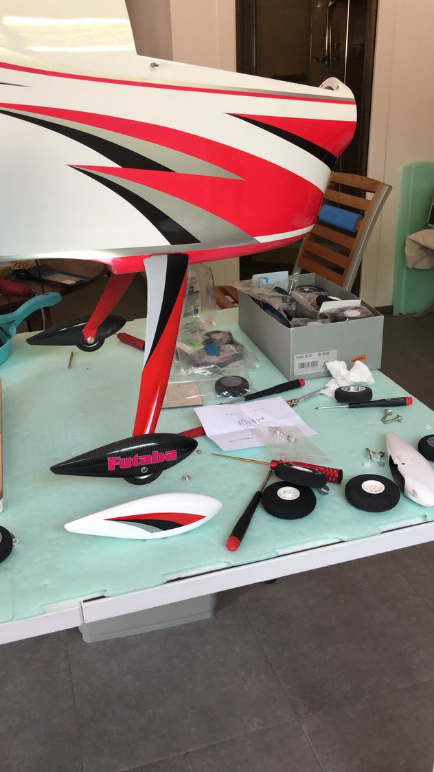
The painted landing gear and wheels pants finally arrived when back home.
After installing the landing gear legs, I had to use other wheels pants, the painted ones needing some reinforcement.
With everything installed I was able using the XICOY
- to weight the plane ready to fly, and with the plane positioned in level flight attitude
- to determine the location of the battery tray to achieve the recommended CG gave by BJ.
I noticed that the Thunder Power TP 5000-5S FAI LINE were 50 g lighter than the ProLiteX Series 25C 5000-5S.
The numbers : ready to fly with TP FAI LINE 5000 mAh, ADVERRUN V3 & D3, FALCON props 23x20, 500 mAh Rx Battery and ULTRAGUARD 430 mAh :
Weight 5050 g
CG at 220 mm from lower wing leading edge
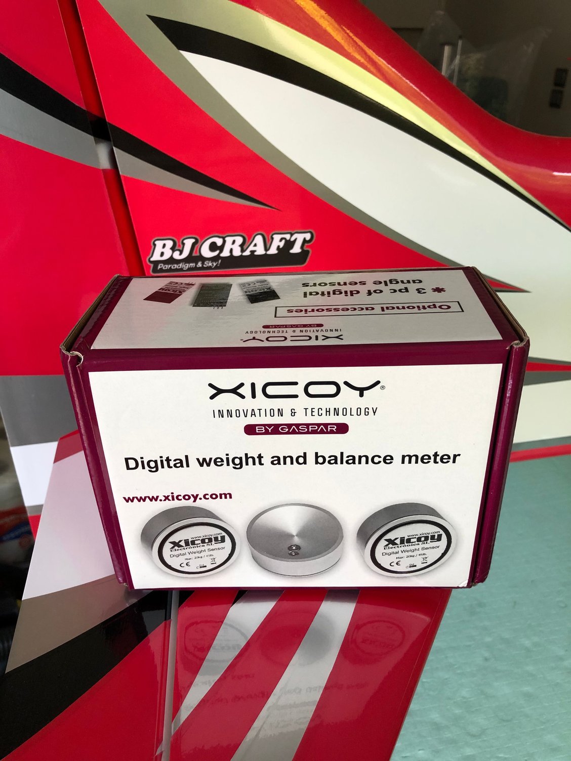
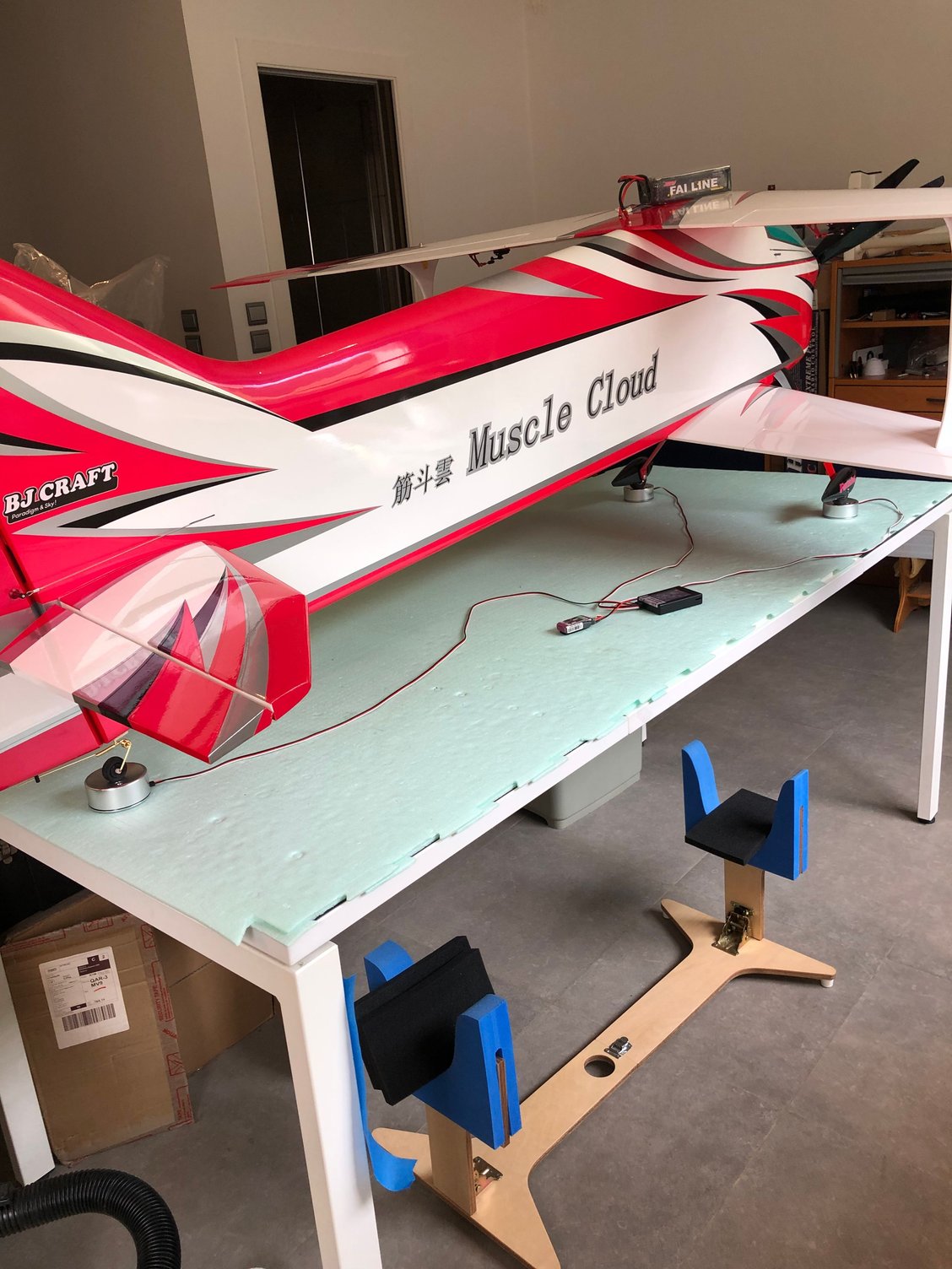

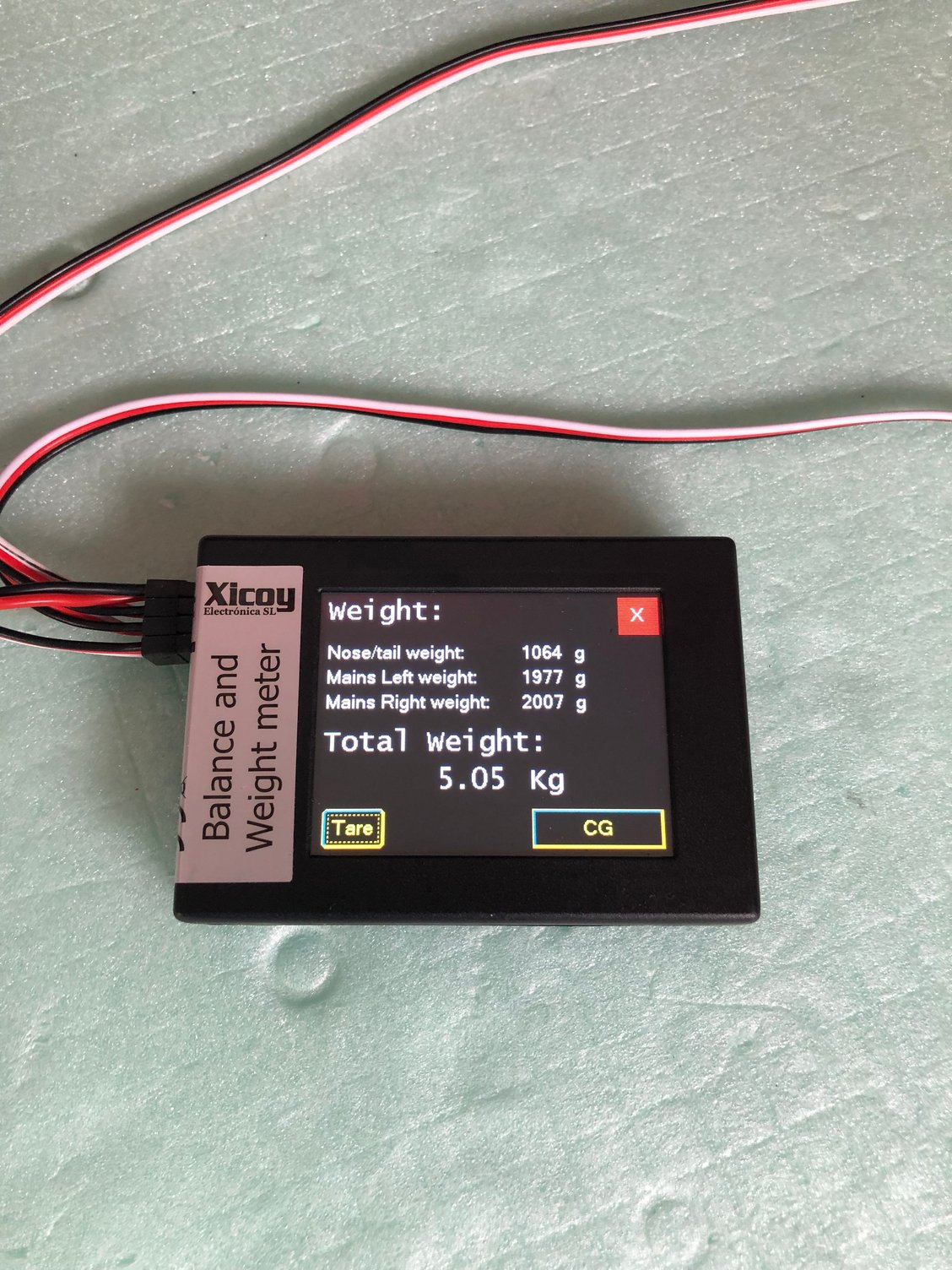
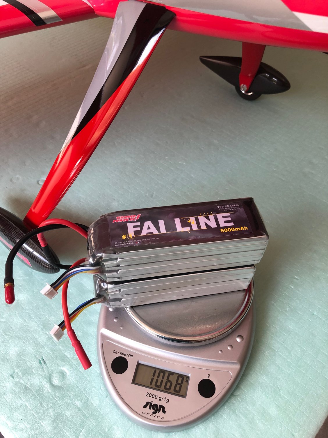
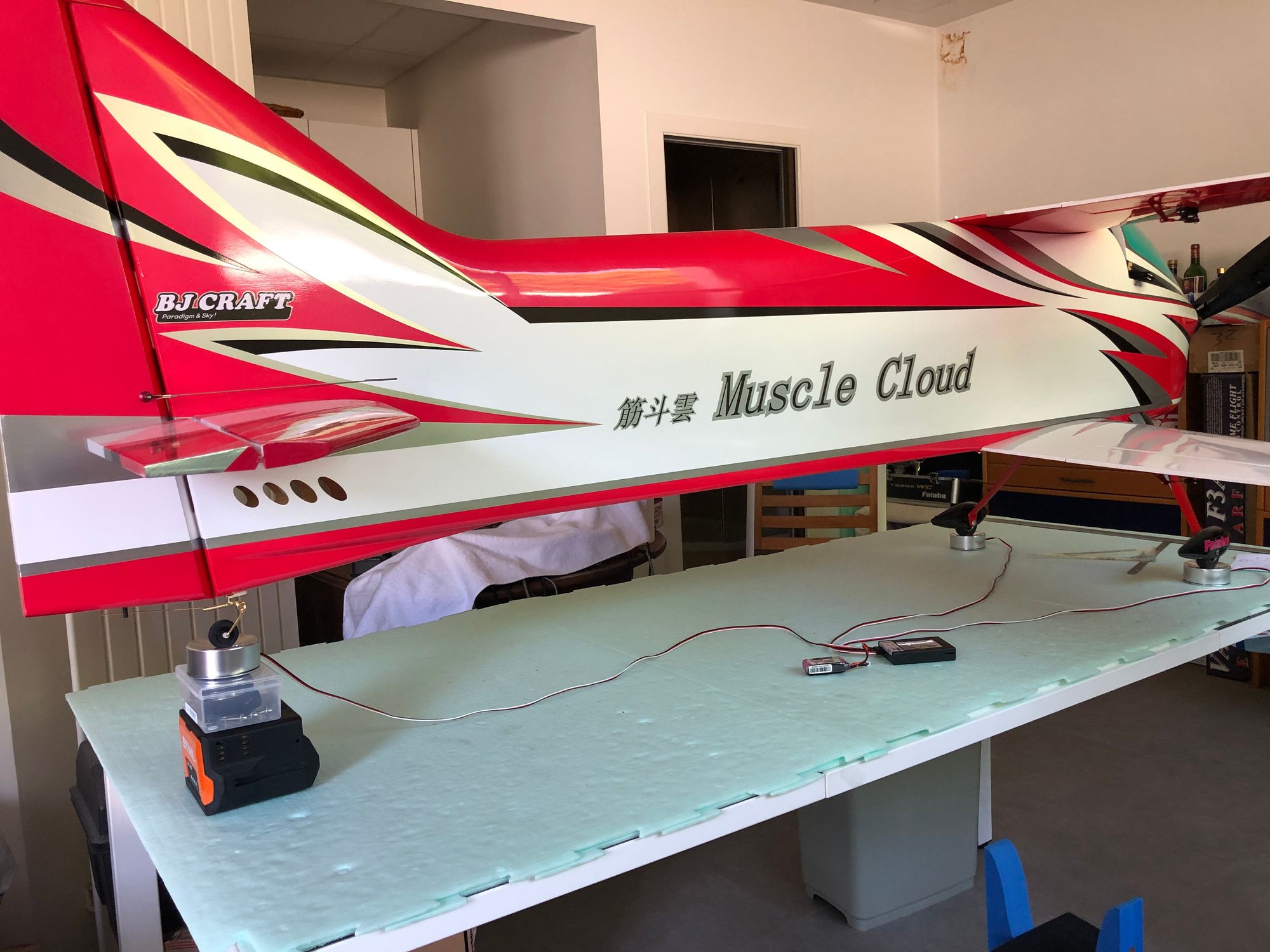
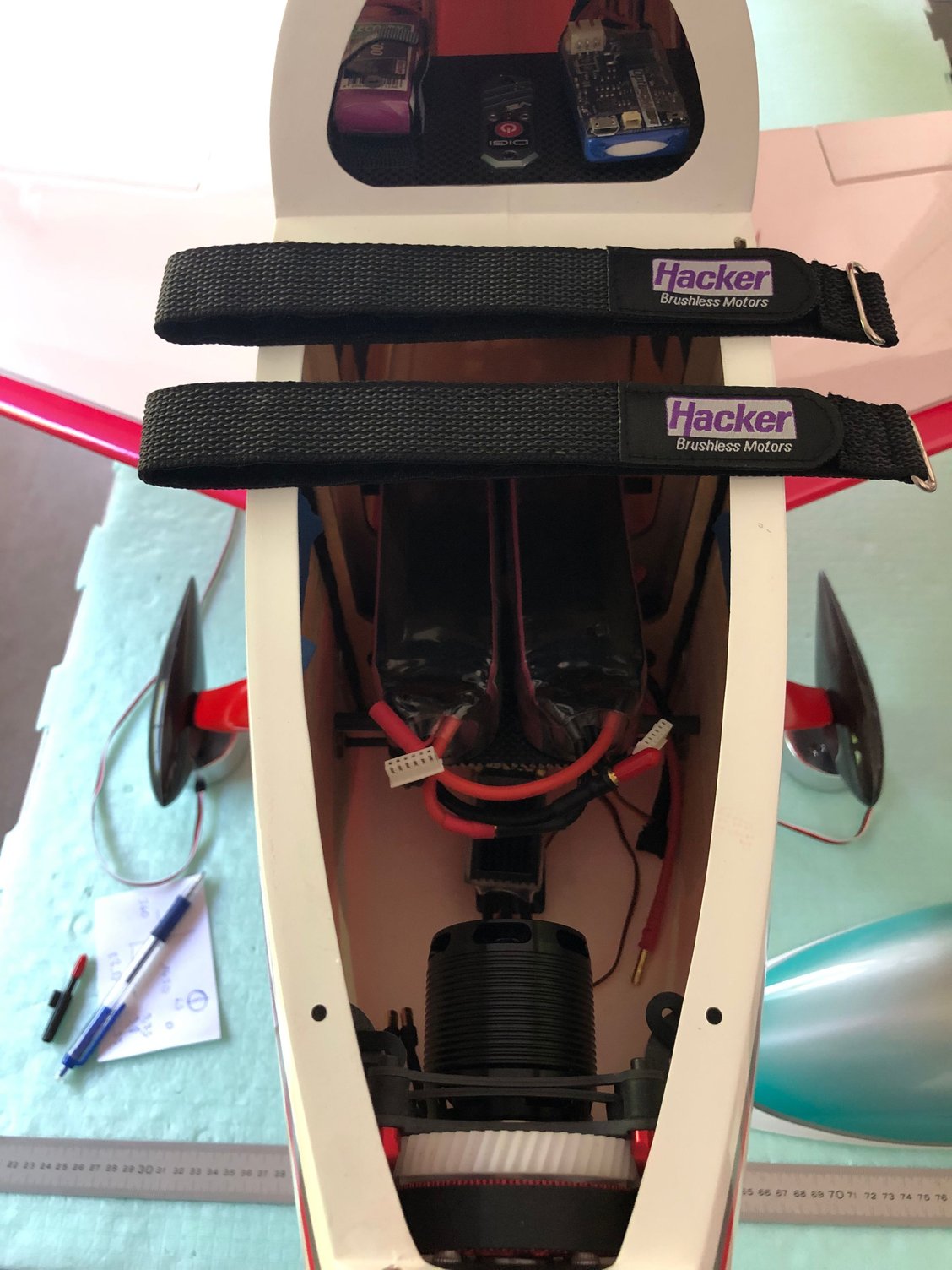
The canopy was removed to adjust the battery tray and battery position.

BJ recommended CG
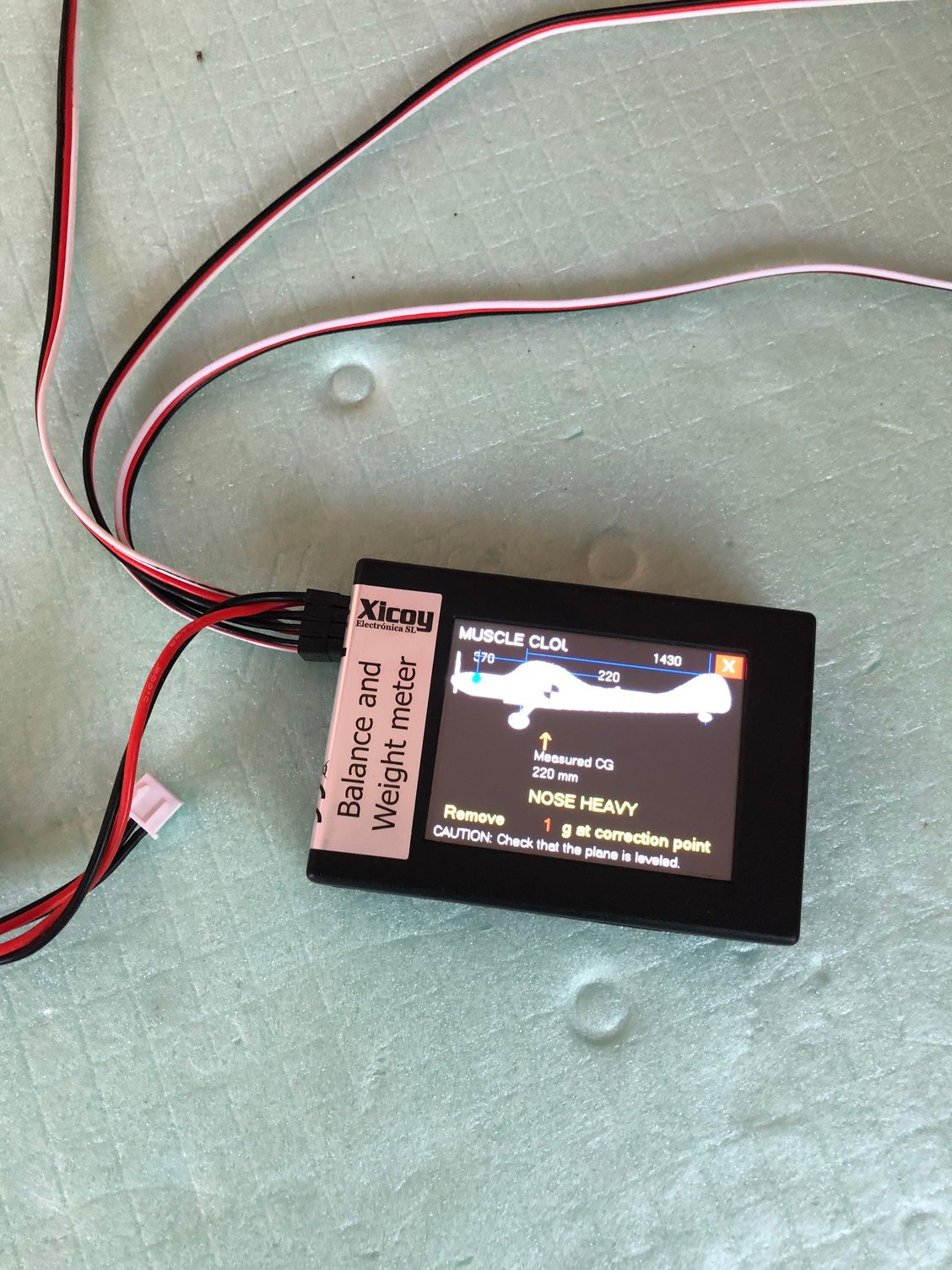
The painted landing gear and wheels pants finally arrived when back home.
After installing the landing gear legs, I had to use other wheels pants, the painted ones needing some reinforcement.
With everything installed I was able using the XICOY
- to weight the plane ready to fly, and with the plane positioned in level flight attitude
- to determine the location of the battery tray to achieve the recommended CG gave by BJ.
I noticed that the Thunder Power TP 5000-5S FAI LINE were 50 g lighter than the ProLiteX Series 25C 5000-5S.
The numbers : ready to fly with TP FAI LINE 5000 mAh, ADVERRUN V3 & D3, FALCON props 23x20, 500 mAh Rx Battery and ULTRAGUARD 430 mAh :
Weight 5050 g
CG at 220 mm from lower wing leading edge
The canopy was removed to adjust the battery tray and battery position.
BJ recommended CG
Last edited by J-P; 06-13-2025 at 03:50 AM.
06-16-2025 | 01:53 AM
#23
Thread Starter
My Feedback: (1)
Installation of battery tray
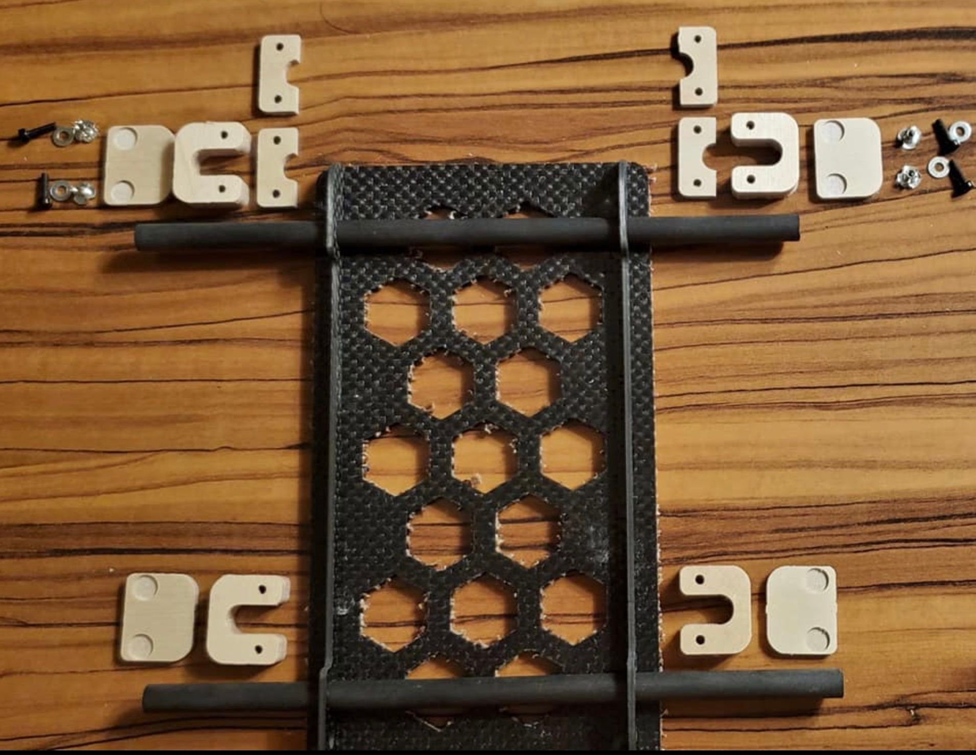
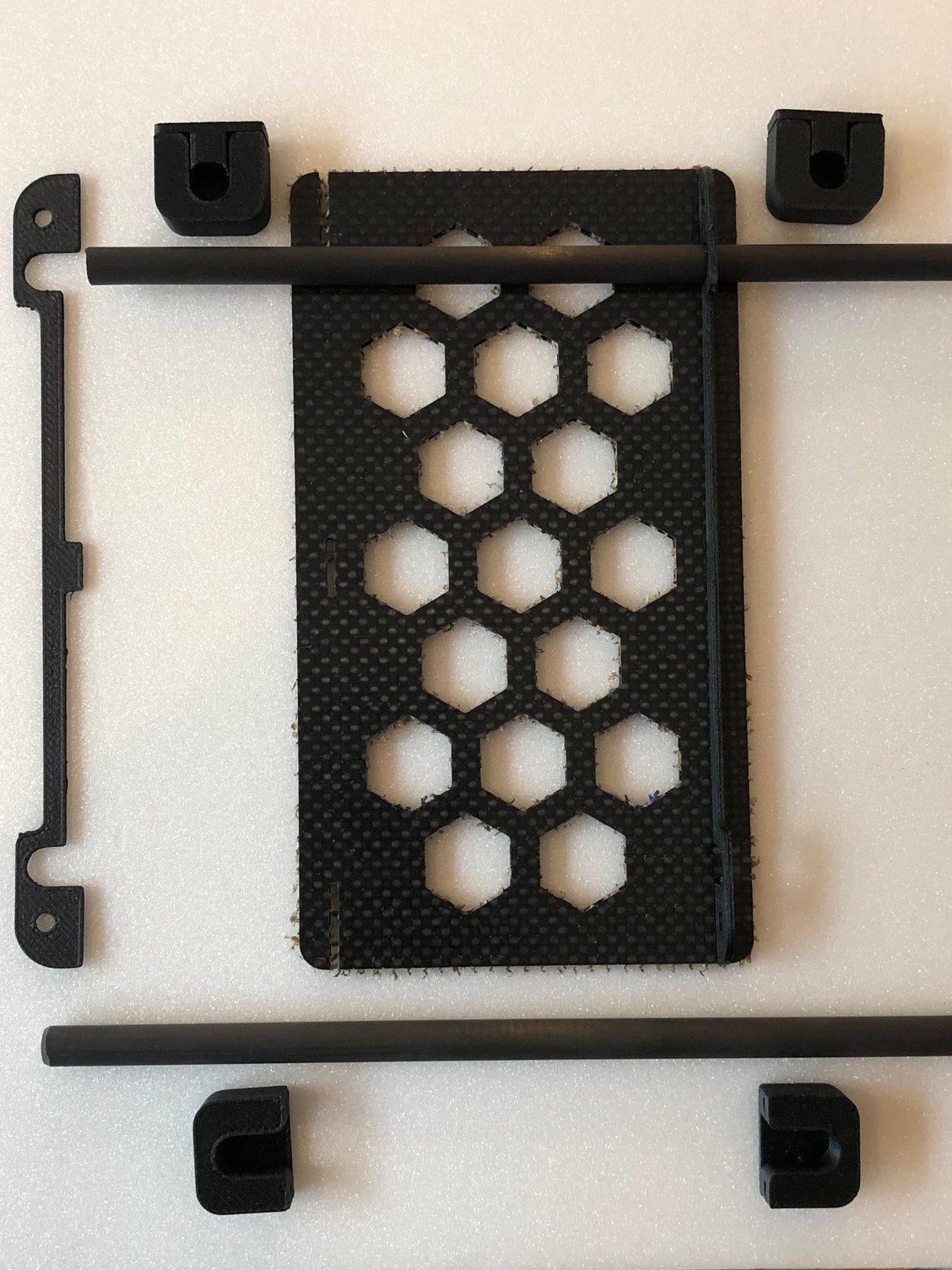
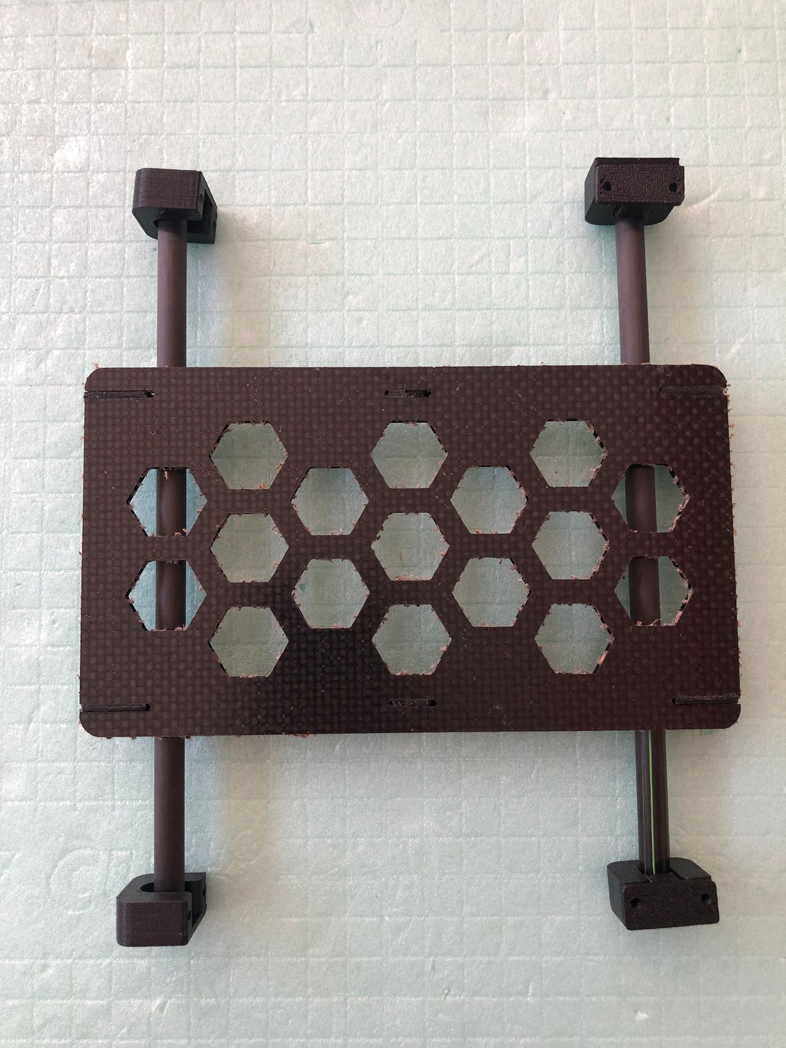
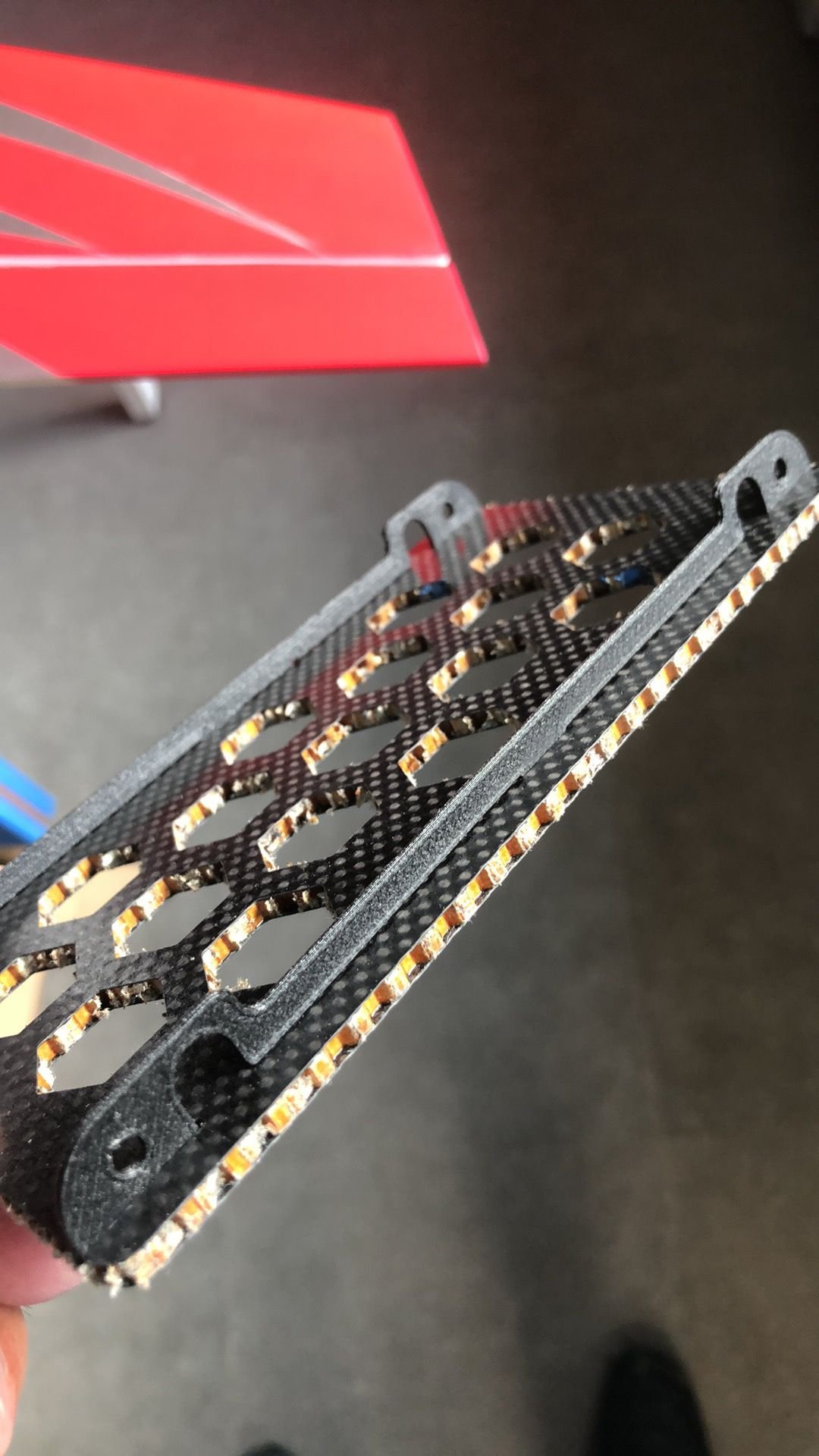
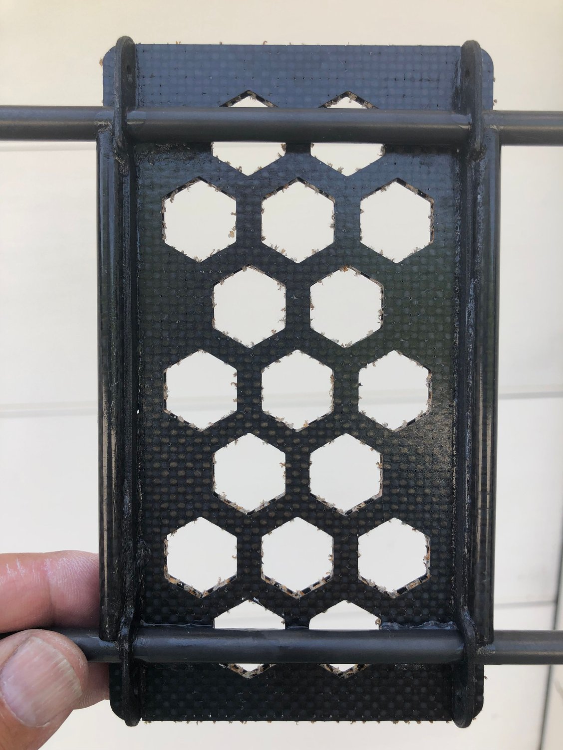
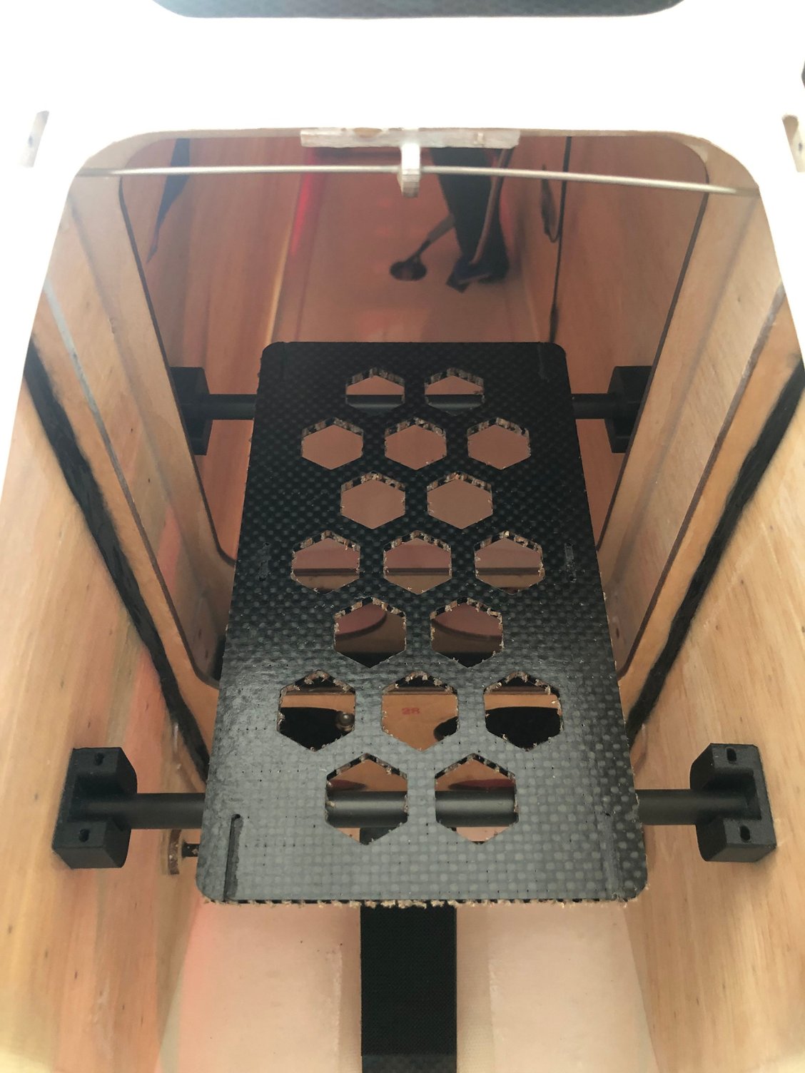
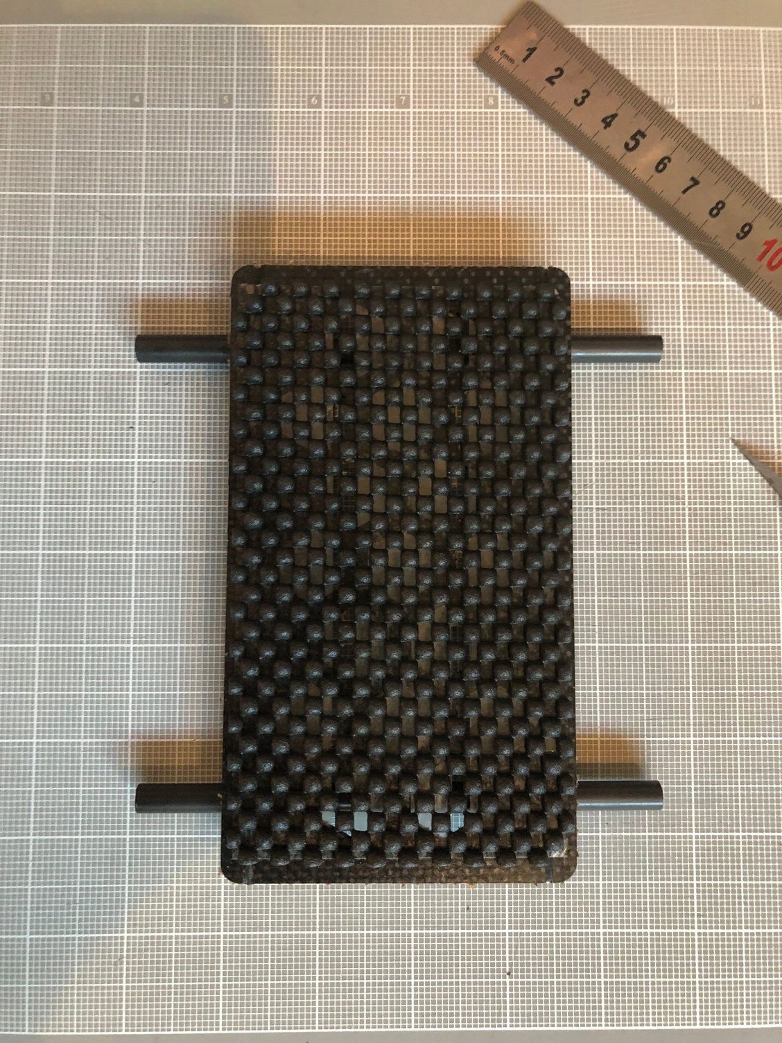
I’m using this nice model , the same as the one installed in the Leader G.
The difference of the new one are the PLA 3D printed parts.
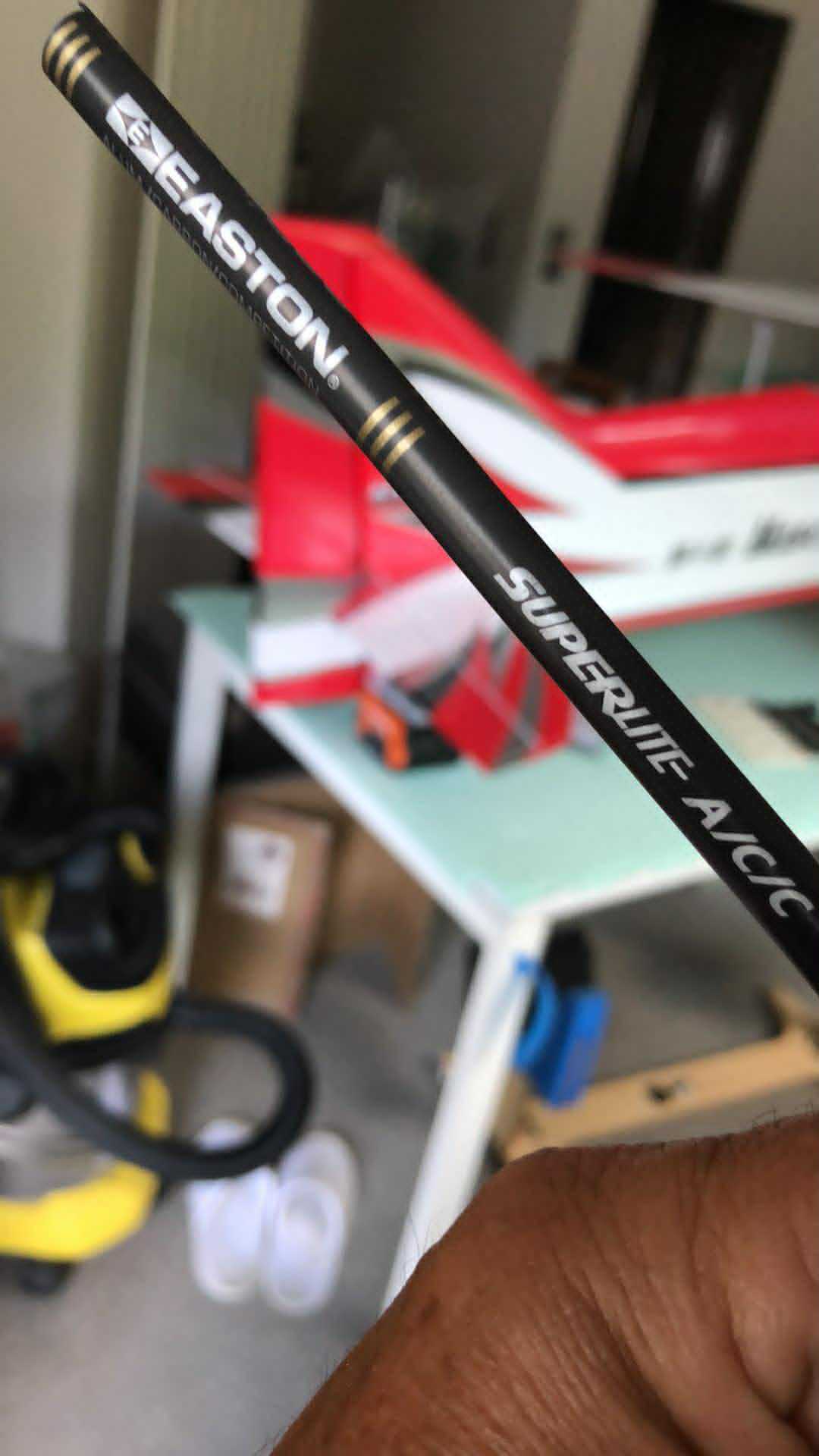
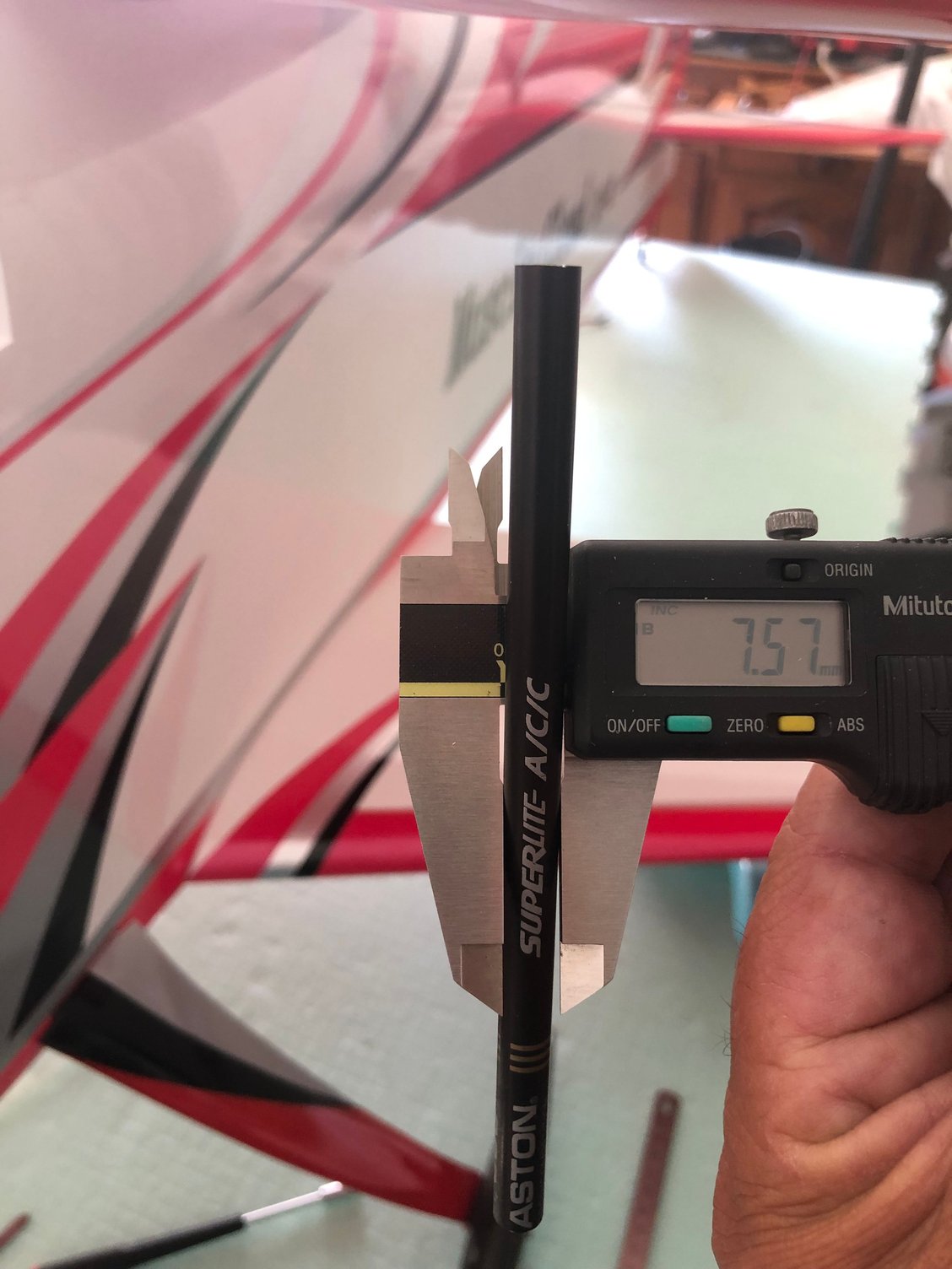
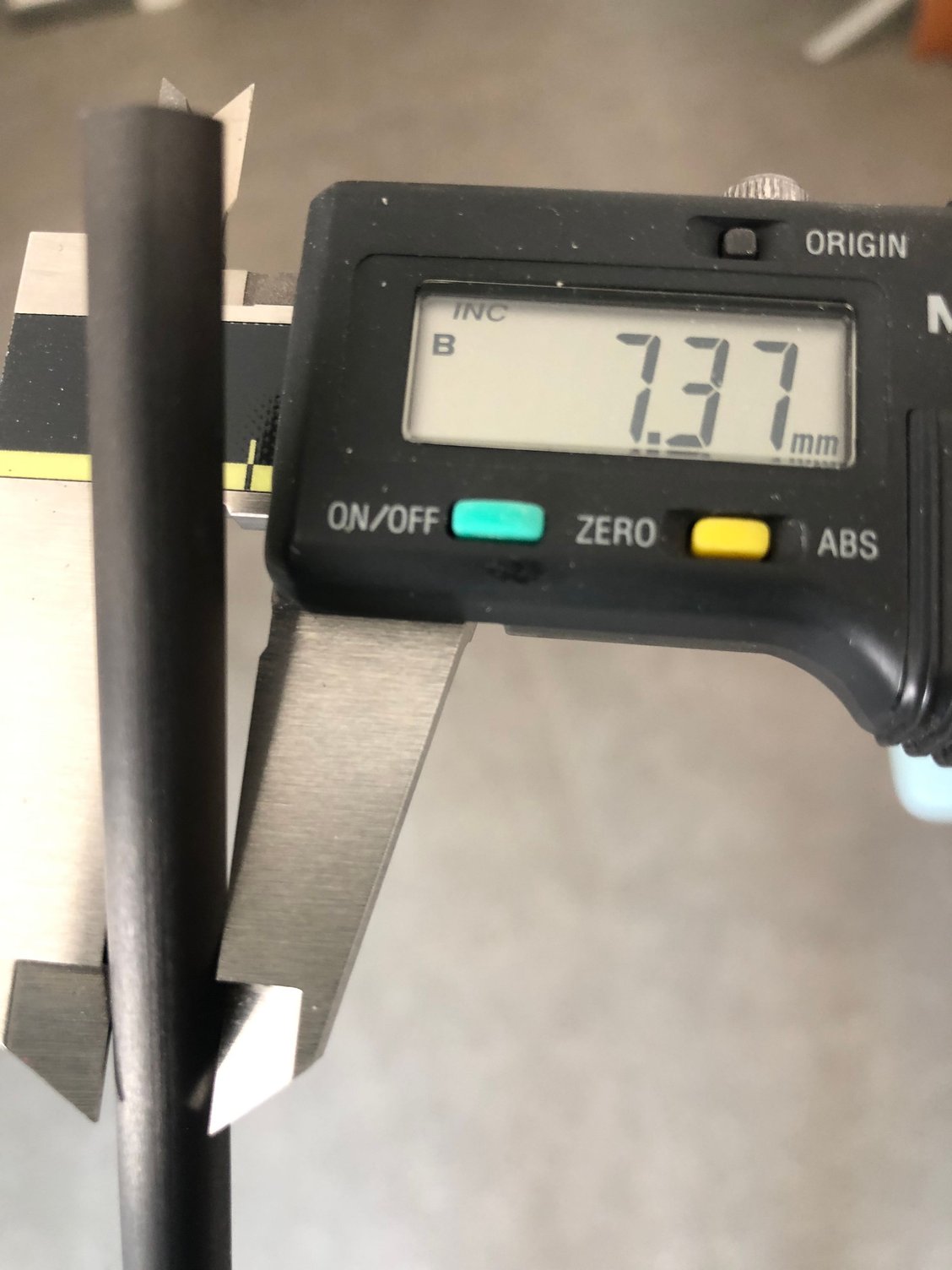
I changed the carbon rods with an EASTON arrow, carbon plus aluminum inside …. recommended by Gregg OKERT 20 years ago
The Easton arrow fits perfectly the news PLA 3D printed supports - slightly larger diameter.
As the previous model was all carbon replaced now by a part in PLA 3D printed, I did a modification I used a 6 mm diameter carbon fiber rod reinforcing the printed parts which in fact hold all the battery weight. This rod is flush to the sides of the support and is mechanically blocked on the front and rear main supports .
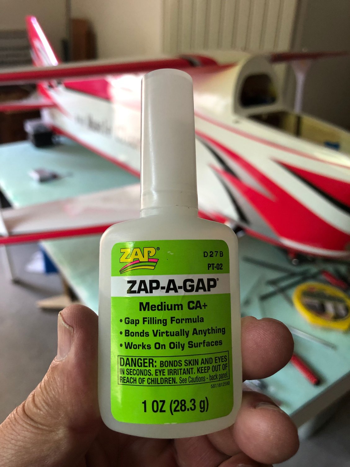
I did some checking - thanks STEVE - and it seems that CA bonds OK to PLA 3D printed material.
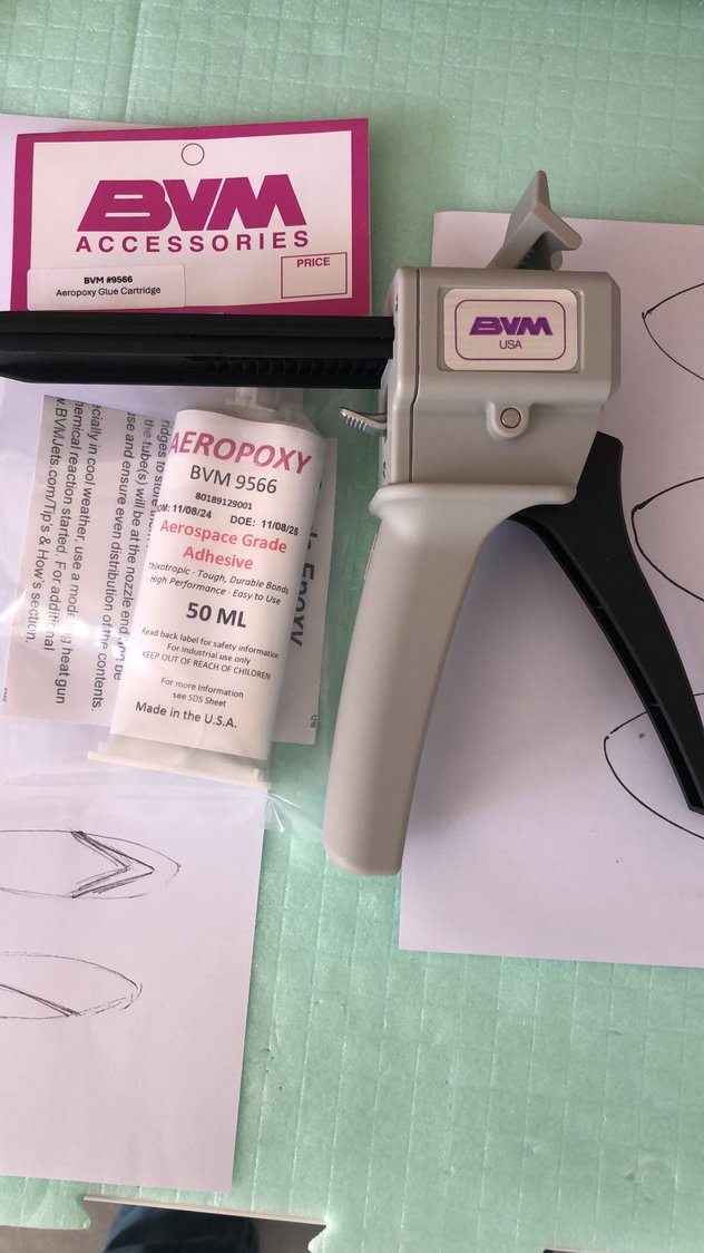
So as per BVM recommendation I used ZAP A GAP, and will reinforce with some BVM Aeropoxy.
Installing the battery tray takes time, but it’s a major part and need to be well secured.
Removable, you have access to the landing gear box, in case ….
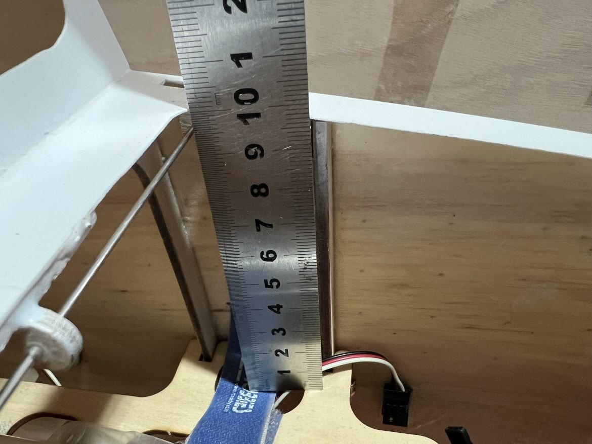
The battery tray must be installed 97 mm below the fuselage where the canopy is standing as per BJ recommendation.
I don't use Velcro for securing the batteries but this non slip material.

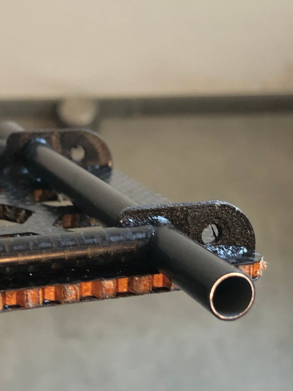
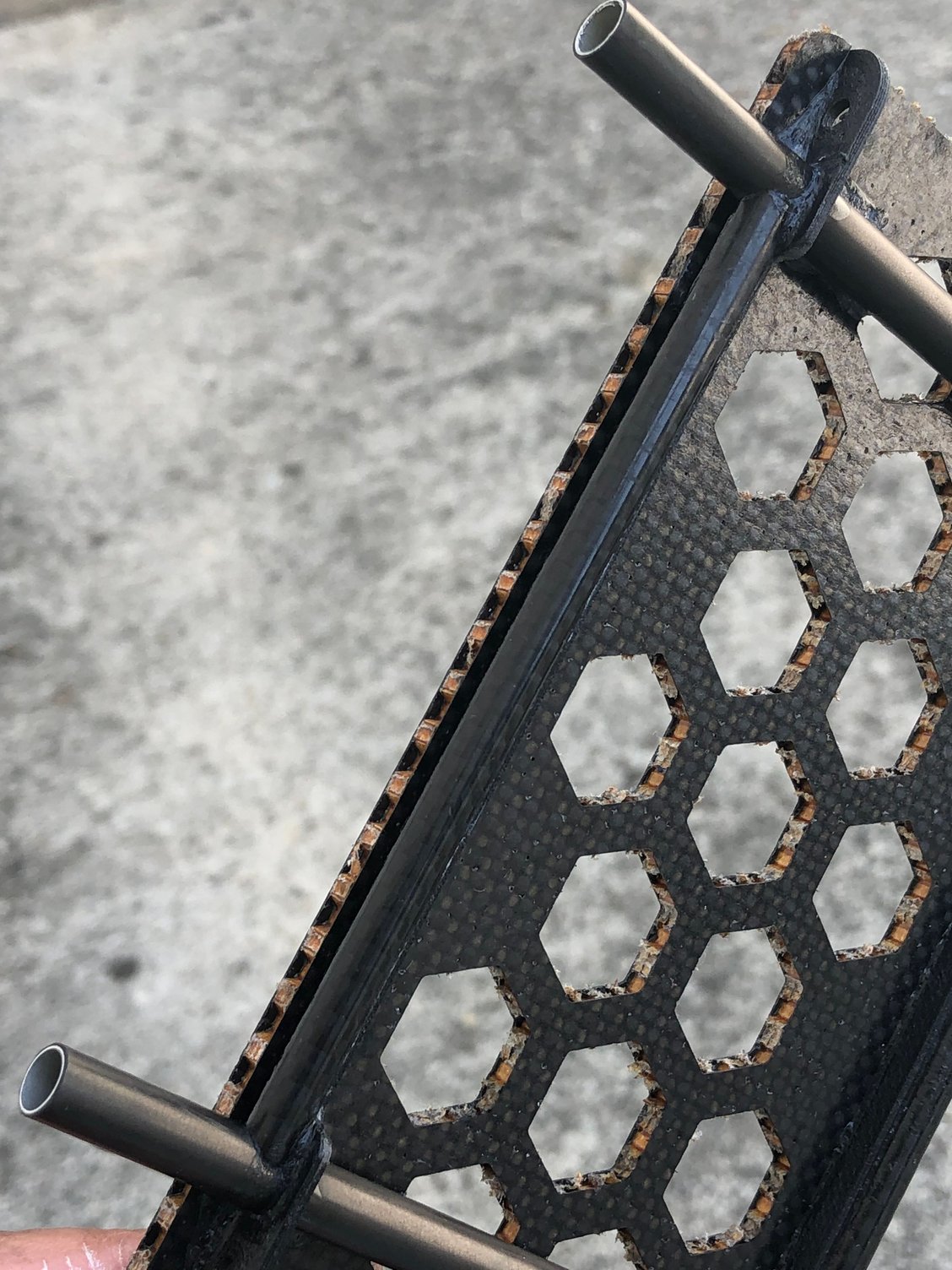
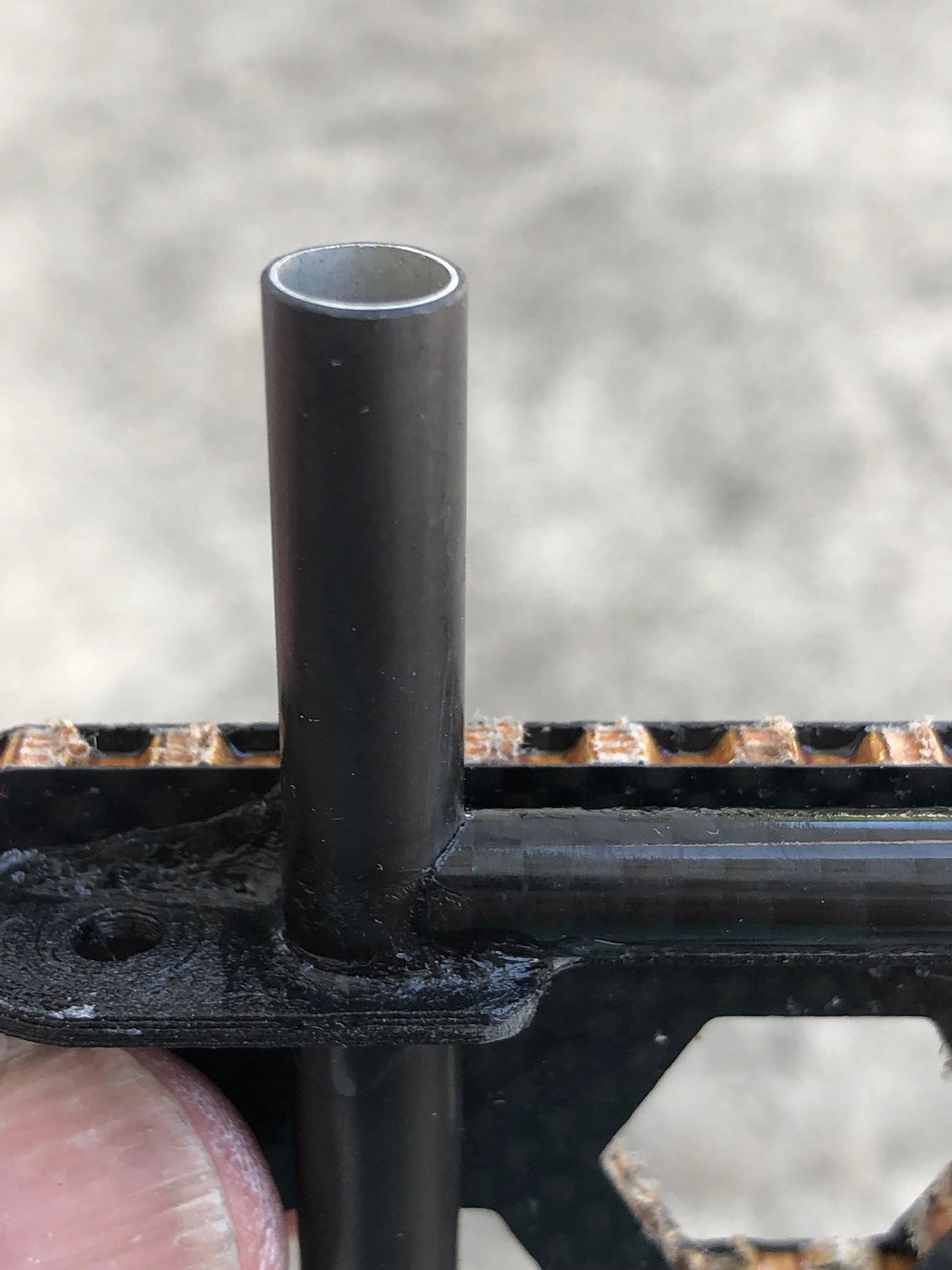

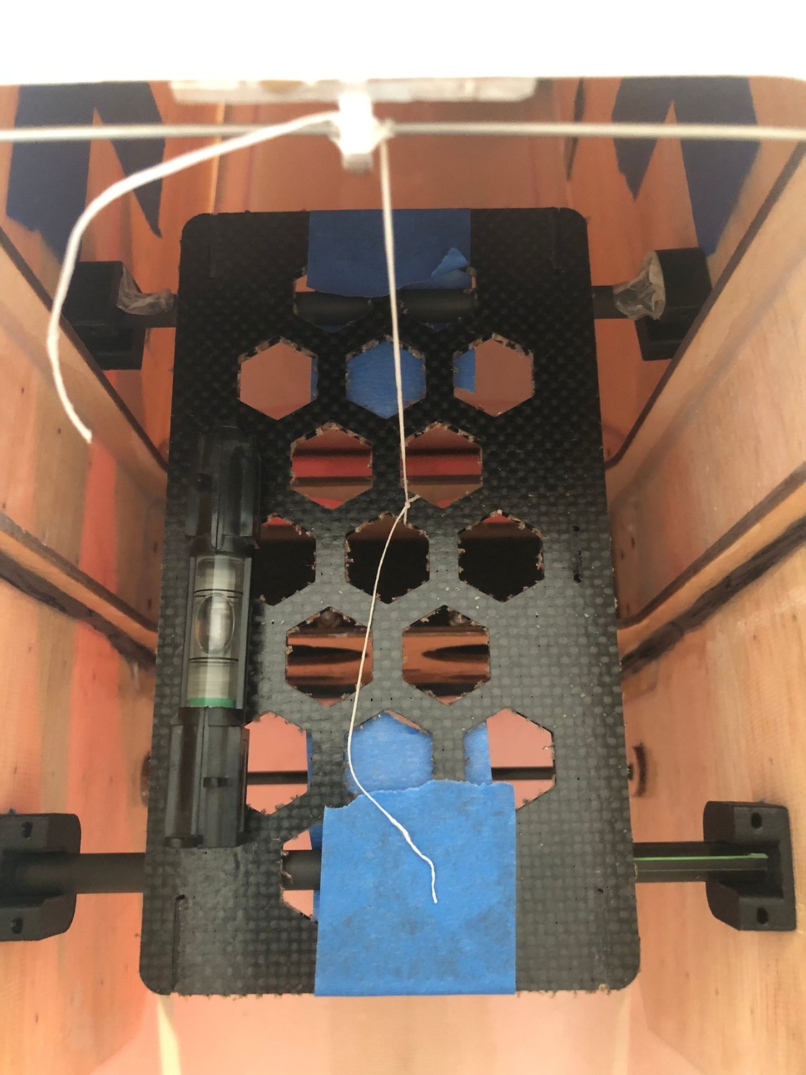

I’m using this nice model , the same as the one installed in the Leader G.
The difference of the new one are the PLA 3D printed parts.
I changed the carbon rods with an EASTON arrow, carbon plus aluminum inside …. recommended by Gregg OKERT 20 years ago
The Easton arrow fits perfectly the news PLA 3D printed supports - slightly larger diameter.
As the previous model was all carbon replaced now by a part in PLA 3D printed, I did a modification I used a 6 mm diameter carbon fiber rod reinforcing the printed parts which in fact hold all the battery weight. This rod is flush to the sides of the support and is mechanically blocked on the front and rear main supports .
I did some checking - thanks STEVE - and it seems that CA bonds OK to PLA 3D printed material.
So as per BVM recommendation I used ZAP A GAP, and will reinforce with some BVM Aeropoxy.
Installing the battery tray takes time, but it’s a major part and need to be well secured.
Removable, you have access to the landing gear box, in case ….
The battery tray must be installed 97 mm below the fuselage where the canopy is standing as per BJ recommendation.
I don't use Velcro for securing the batteries but this non slip material.
06-20-2025 | 11:11 PM
#24
Thread Starter
My Feedback: (1)
Close to the maiden flight
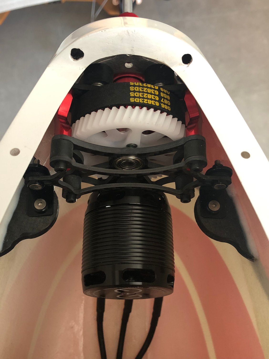
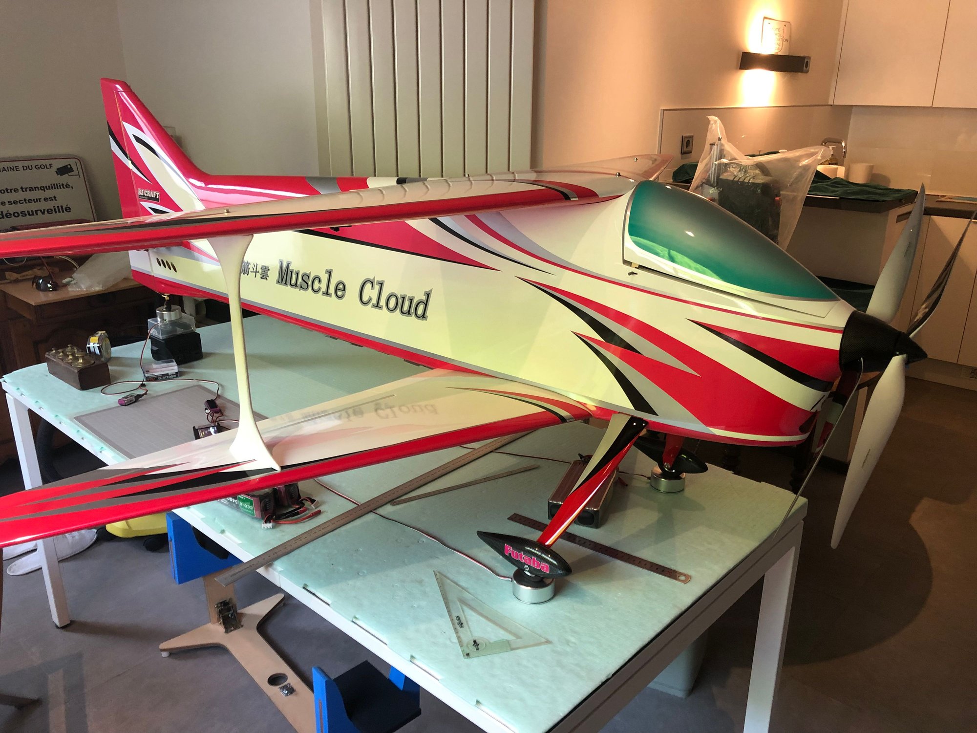
Muscle Cloud is now ready.
ADVERRUN V3 is installed with a D3 ESC and a pair of FALCON 23 X20 props
FUTABA T32 WC radio is programmed, failsafe checked with both RX.
I asked BJ confirmation about the CG :
He recommend 220 mm in Europe, while in hot and thin air area 230 to 240 mm
Muscle Cloud MAC is 265mm, and with the sweep back wing , he said there is a very wide range.
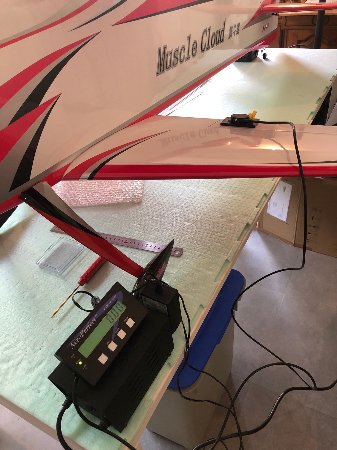
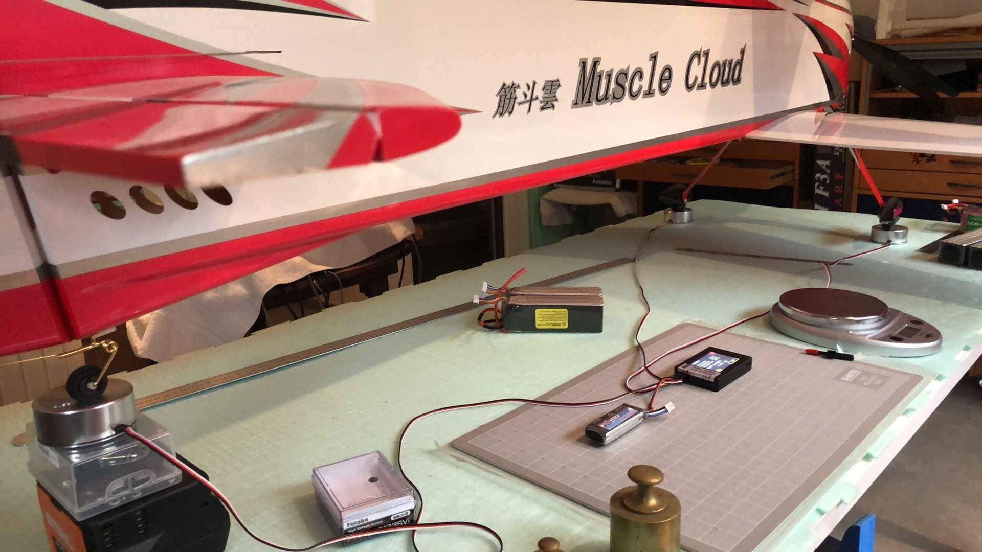
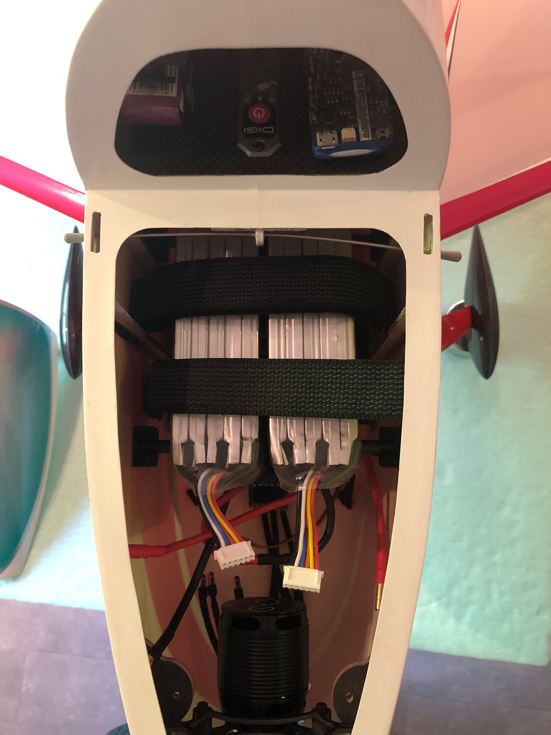
The Xicoy is the perfect tool to determine accurately the battery position of different packs to achieve the required CG :
Position of THUNDER POWER F3A LINE 5000, HACKER 5400, THUNDER POWER 6000
Looking to my plane pictures, he remarked I had changed the standard landing gear by a canard type.
So he think I could experience some yaw stability problems, and recommend in this case to use a rudder drag plate
For memory wing fences are included in the kit with a setting jig.
BJ said they are related with spin entry only and necessary for thin air, high altitude flying field, or nose heavy settings.
He think as temperature is lower in Europe than in Singapore or Zhuhai, they should not be needed.
Temperature in Paris are expected to be 35 °C this weekend, so I will wait for more European temperatures for the first flight..
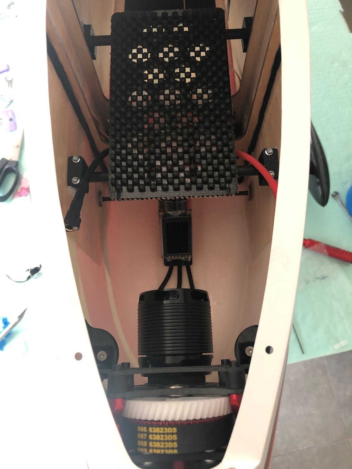

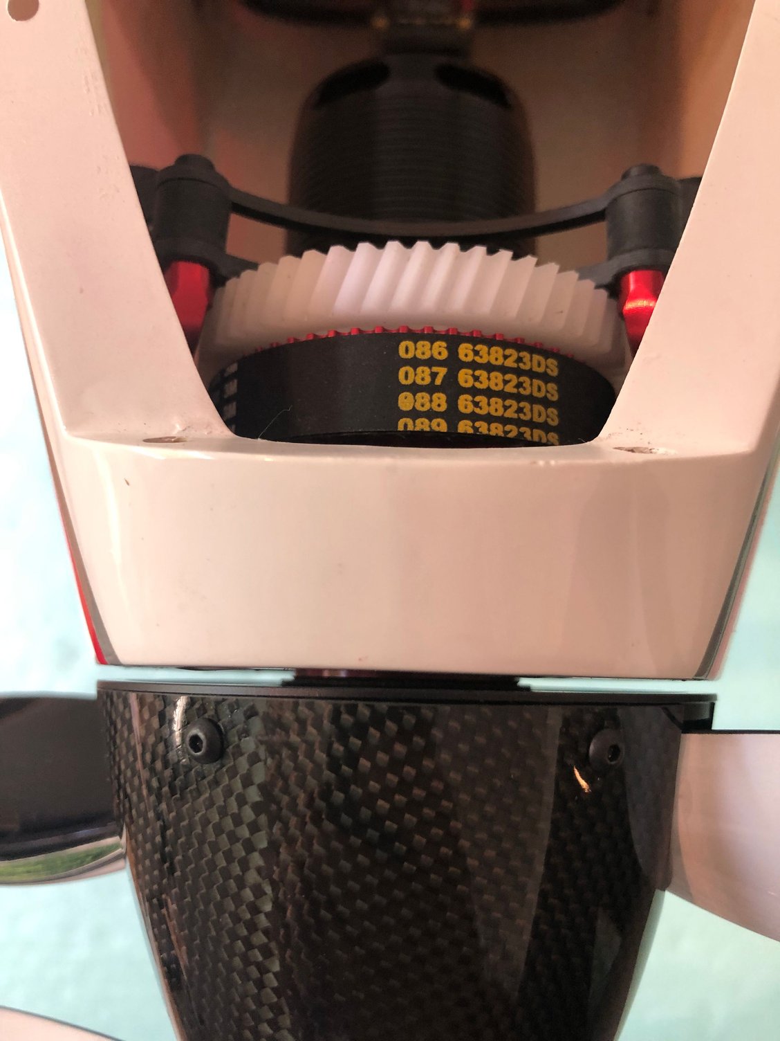
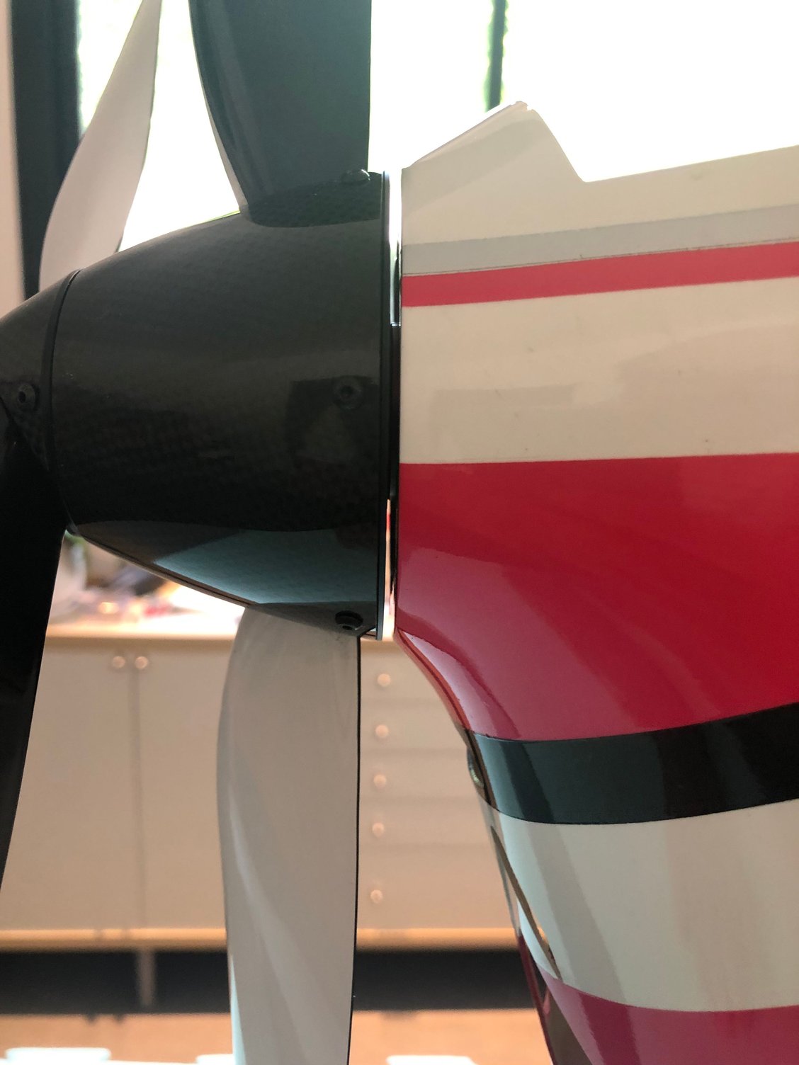
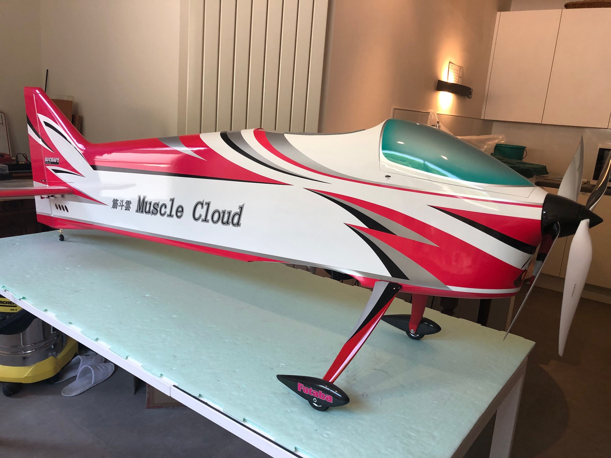
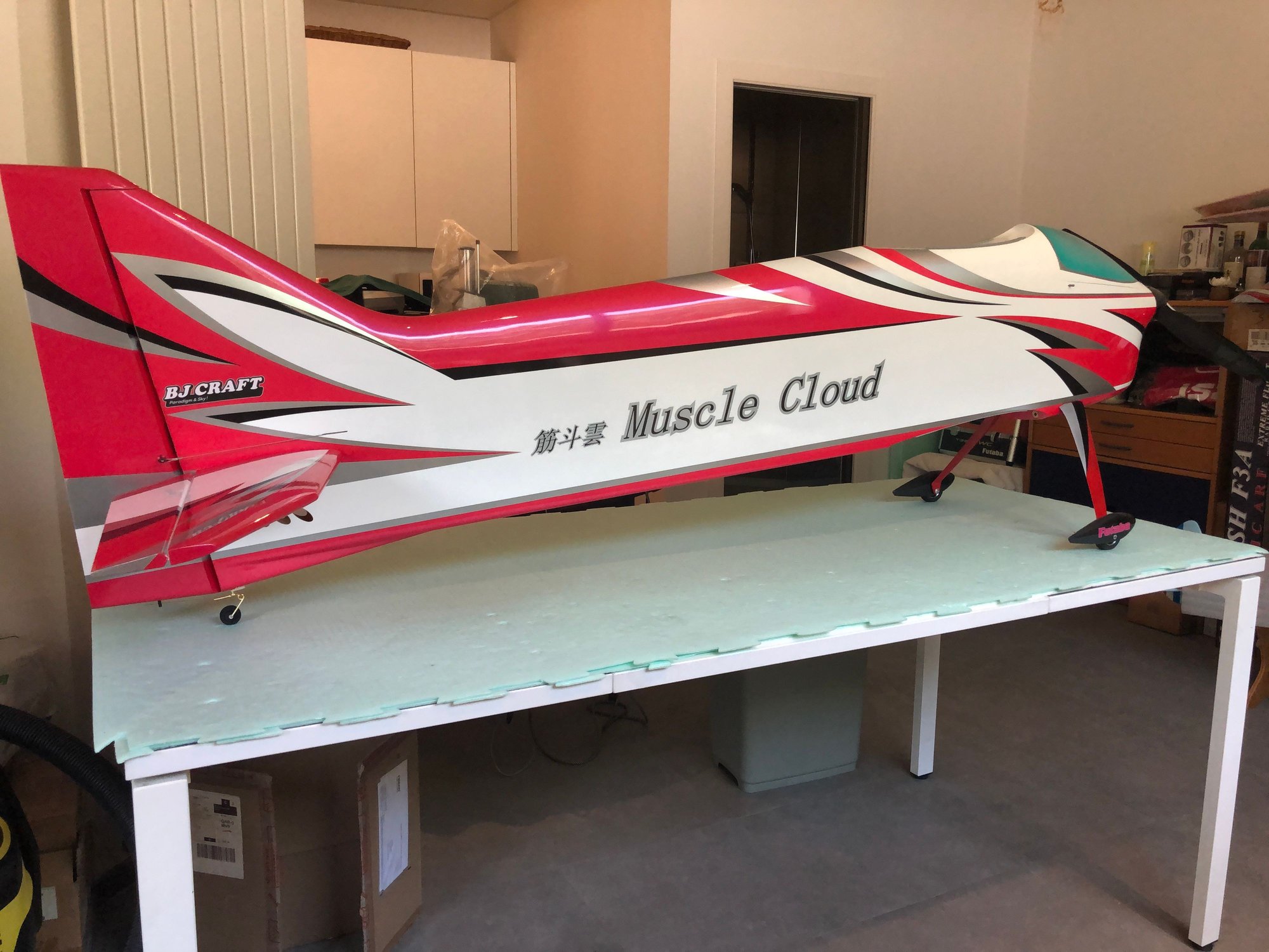
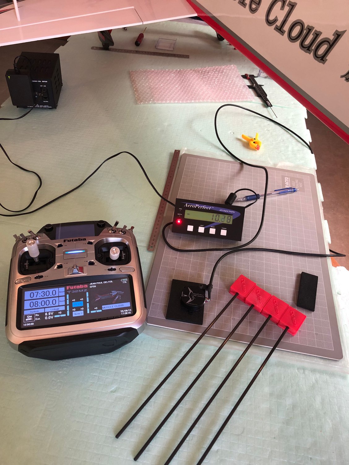
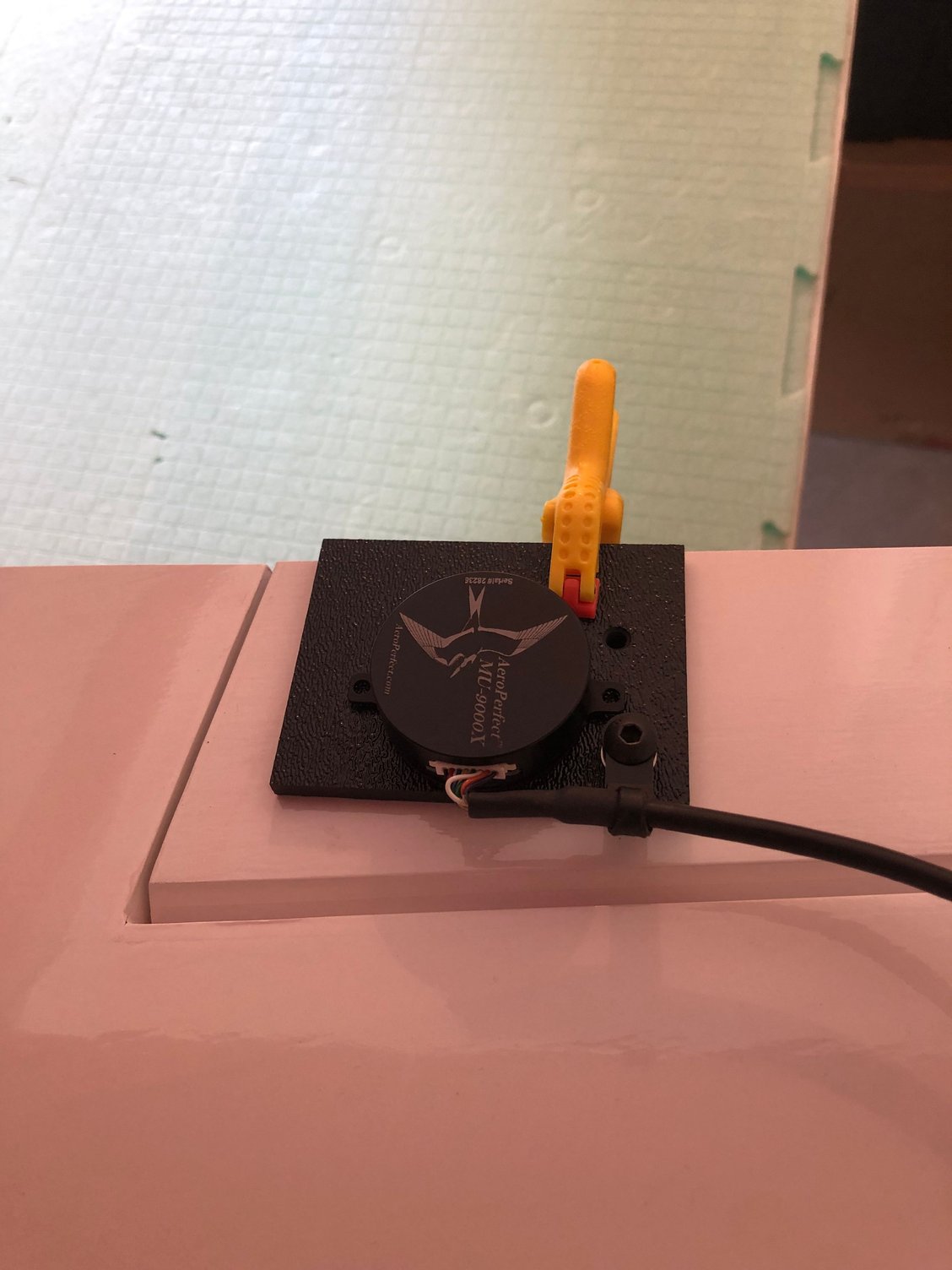
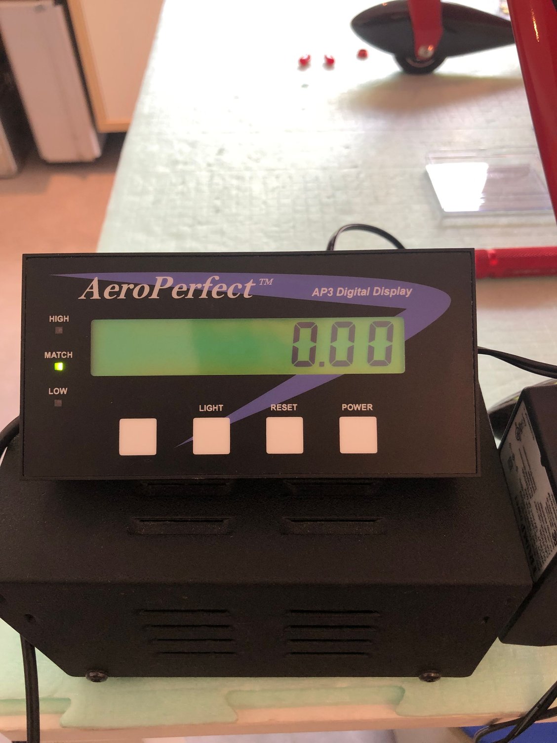
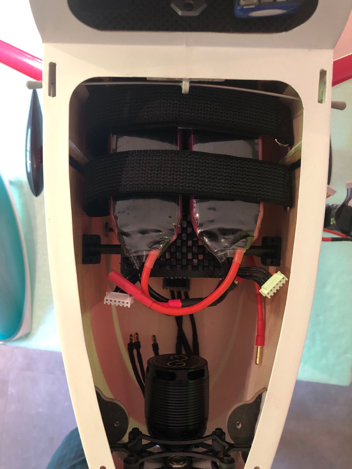
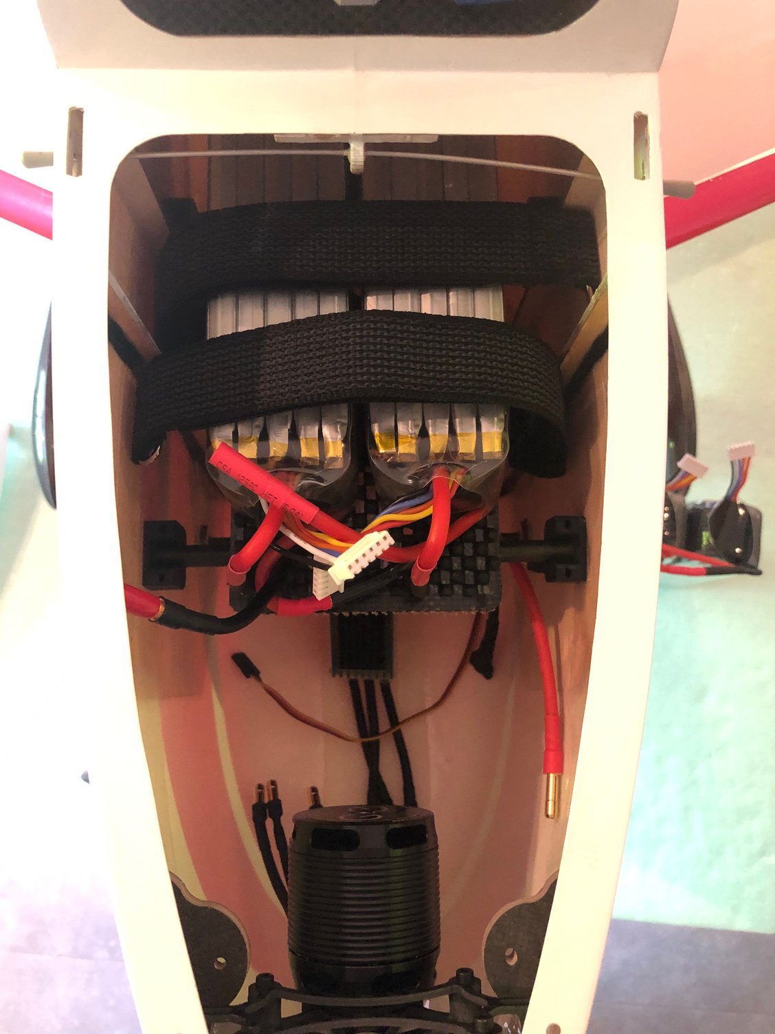
Muscle Cloud is now ready.
ADVERRUN V3 is installed with a D3 ESC and a pair of FALCON 23 X20 props
FUTABA T32 WC radio is programmed, failsafe checked with both RX.
I asked BJ confirmation about the CG :
He recommend 220 mm in Europe, while in hot and thin air area 230 to 240 mm
Muscle Cloud MAC is 265mm, and with the sweep back wing , he said there is a very wide range.
The Xicoy is the perfect tool to determine accurately the battery position of different packs to achieve the required CG :
Position of THUNDER POWER F3A LINE 5000, HACKER 5400, THUNDER POWER 6000
Looking to my plane pictures, he remarked I had changed the standard landing gear by a canard type.
So he think I could experience some yaw stability problems, and recommend in this case to use a rudder drag plate
For memory wing fences are included in the kit with a setting jig.
BJ said they are related with spin entry only and necessary for thin air, high altitude flying field, or nose heavy settings.
He think as temperature is lower in Europe than in Singapore or Zhuhai, they should not be needed.
Temperature in Paris are expected to be 35 °C this weekend, so I will wait for more European temperatures for the first flight..
The following users liked this post:
rcprecision (06-21-2025)
06-21-2025 | 01:36 PM
#25

My Feedback: (26)
Joined: Sep 2002
Posts: 215
Likes: 0
Received 0 Likes
on
0 Posts
From: Springfield, MA
J-P
The D3 esc is suppose to be mounted an inch or two behind the air intake so it gets a direct blast of air, otherwise it may overheat. It looks like you have it mounted pretty far back.
The D3 esc is suppose to be mounted an inch or two behind the air intake so it gets a direct blast of air, otherwise it may overheat. It looks like you have it mounted pretty far back.

