


Electronic solutions to modifying glow engines of all sizes to gasoline
 11-11-2022 | 07:47 AM
#1126
The take-off surprised me a bit, I expected to be able to notice it becoming light before taking off, but turned out one moment it was rolling and the next moment it was 5 feet up.
From there it felt a bit sluggish for a few seconds before it gained some speed and steadied up. I did not retract the gear, and I did not push WOT too much, so I have no clue at all if it is fast or not. Due to the stress and focus, I had no time to take a look at engine temperature or airspeed (and I forgot to activate the log functions).
But all in all, I have confidence that the plane itself will fly without issues if the landing gear allows it. My biggest fear is that the repair is not adequate, because the glue-spots were hard to reach.
On full size AC the trailing link landing gear is generally known for bing a "soft" gear but I don't think its use on a nose gear is very wide spread and probably or some of the reasons you are seeing. Nose strut length is very critical (for setting ground attitude) but it becomes less critical if a plane has more effective of elevator control. You rarely hear a Twin Otter pilot snag or complain about a nose gear strut as the pitch control is very powerful. Some other planes on the other hand are touchy and Incorrect strut height causes a variety of take off "weirdness". While I agree that the strut is causing issues it might be an issue of elevator effectiveness adding to the issue.
By how it landed (rewatched the vid over and over) my conclusion is that CoG is a bit forward, and although next flight (tomorrow) will be done with this CoG, subsequent flights I will take 10 grammes out of the nose every flight until I am satisfied with attitude control during landing That is, IF the nose gear survives tomorrow.
But if all goes well, our ClubStalker Rob (who also helped design this plane) will bring his FPV drone and hopefully he can produce some marvellous footage. And if so, of course I will upload and post that here. Fingers crossed!
.
 11-11-2022 | 08:33 AM
#1127
5" behind the CG seems way far back for the mains. The aircraft will likely not want to rotate on take off without a lot of speed and elevator, then all of a sudden leap off the runway risking a stall. With the mains that far behind CG it's doubtful moving the CG back will help much with taking weight off the NG but will certainly help with the landing speed envelope.
Last edited by Glowgeek; 11-11-2022 at 08:53 AM.
11-11-2022 | 09:19 AM
#1128
5" behind the CG seems way far back for the mains. The aircraft will likely not want to rotate on take off without a lot of speed and elevator, then all of a sudden leap off the runway risking a stall. With the mains that far behind CG it's doubtful moving the CG back will help much with taking weight off the NG but will certainly help with the landing speed envelope.
I knew the 5" was a bit far back, and I did expect problems with rotating, but because of no other option, the stance of 3,5 degrees positive was chosen. That would ensure a take-off at sufficient airspeed. And in all fairness, when it comes to take-off, I prefer not being able to rotate but the LG dictating take-off speed. Better that, than pulling hard to lift the plane off and immediately go into a stall.
Now there is this thing with CoG, that it is not in its final position yet, it could possibly move aft by up to an inch (not expected, but possible) so we are going to adapt the drawings once final CoG is known. Relocating that main spar.
Tomorrow I hope to learn more.
On a more positive note: I was able to actually and accurately measure static thrust, and it turned out way better than P� Reivers' propcalc indicated.
@12K RPM I measured 1,95 kgf, while the calculator indicated only 1,55 kgf at that RPM.
That probably is because P�'s sheet takes the fuselage drag into account.
Modifying the muffler into a "pusher pipe" kept the plane a lot cleaner on the test-table, and also changed the exhaust note a bit, the tailpipe now blowing straight into the prop arc, but it makes choking a lot nastier when the muffler is hot...
Last edited by 1967brutus; 11-11-2022 at 09:26 AM.
11-11-2022 | 10:11 AM
#1129

That was actually the issue: Static, it stands 3,5 degrees positive. When rolling, the nose dips with increasiong speed until fully compressed at 0,9 degree negative: The nose (measured at the tip) dips almost 2,5" from full extended to full compressed nosegear. Those O-rings start interfering with spring stiffness at +2,6 degrees, so I have good hope the nose dipping will be limited to that.
Remember that geometry I was talking about? The first 3/4" of nose dip allready compresses the spring halfway through its travel. the remaining 1-3/4"of nose dip is spread over the remaining half of the spring travel, That is that change in leverage, and the spring being linear means that the resulting returnforce is not...
The issue is compounded by main gears with rather stiff springs and a rather progressive linkage.
To be honest, I think these legs are designed more for looks than for practicality.
 ... it was probably designed by a young labor from over seas... if you can get at the spring, replace it with one that offers a bit more preload on the nose gear
11-11-2022 | 10:23 AM
... it was probably designed by a young labor from over seas... if you can get at the spring, replace it with one that offers a bit more preload on the nose gear
11-11-2022 | 10:23 AM
#1130
Bert, this CG calculator is excellent. I used it to determine CG on a scratch built pattern plane I got a few years back. I entered in the required dimension values, set the static margin to 15%, hit the calculate button and maiden went off without a hitch.
https://www.ecalc.ch/cgcalc.php
https://www.ecalc.ch/cgcalc.php
11-11-2022 | 10:46 AM
#1131
5" behind the CG seems way far back for the mains. The aircraft will likely not want to rotate on take off without a lot of speed and elevator, then all of a sudden leap off the runway risking a stall. With the mains that far behind CG it's doubtful moving the CG back will help much with taking weight off the NG but will certainly help with the landing speed envelope.
11-11-2022 | 11:32 AM
#1132
Hence the O-rings on the outside of that plunger. What I can do, is have a buddy of mine, who is a CNC expert, make a swingarm with a different linkage that provides a more progressive springrate. But that will cause all kind of trouble with the shape and size of the wheelbay...
Tomorrow I'll know if the O-rings will work.
.
11-11-2022 | 12:34 PM
#1133
Well you could wind your own from some music wire... I use to make my own sprung loaded steerable tailwheels that worked a treat... different application I know, but still they turned out to work better than the ones that came in the package.
Check out The Spring Store also:
https://www.thespringstore.com/
Check out The Spring Store also:
https://www.thespringstore.com/
11-11-2022 | 12:39 PM
#1134
As I said, I don't see options to wind a heavier gauge than what they used, on such a narrow core. I am not able to find any heavier springs commercially and I am not able to wind my own.
It appears to be a 0,8 mm wire wound to a 5 mm outside diameter, meaning the core has to be about 3 mm or maybe even narrower than that to end up with that outer diameter.
I am stuck with that outer diameter, since the spring is in a bore inside the leg. Using 1 mm wire would only require an even narrower core.
I have no means to do that without overstressing the wire.
11-11-2022 | 02:40 PM
#1135
As I said, I don't see options to wind a heavier gauge than what they used, on such a narrow core. I am not able to find any heavier springs commercially and I am not able to wind my own.
It appears to be a 0,8 mm wire wound to a 5 mm outside diameter, meaning the core has to be about 3 mm or maybe even narrower than that to end up with that outer diameter.
I am stuck with that outer diameter, since the spring is in a bore inside the leg. Using 1 mm wire would only require an even narrower core.
I have no means to do that without overstressing the wire.
It appears to be a 0,8 mm wire wound to a 5 mm outside diameter, meaning the core has to be about 3 mm or maybe even narrower than that to end up with that outer diameter.
I am stuck with that outer diameter, since the spring is in a bore inside the leg. Using 1 mm wire would only require an even narrower core.
I have no means to do that without overstressing the wire.
11-12-2022 | 01:11 AM
#1136
I could try and figure that out, bt I ain't got the time left for that.
But in all fairness, I don't think packing the springbox will help, because it does not change the regressive characteristic of the linkage.
The O-rings make that a "second spring" comes in halfway the travel... Not the same as a progressive wound spring, but a bit similar.
But in all fairness, I don't think packing the springbox will help, because it does not change the regressive characteristic of the linkage.
The O-rings make that a "second spring" comes in halfway the travel... Not the same as a progressive wound spring, but a bit similar.
11-12-2022 | 08:23 AM
#1137
Looks like I really have to redesign the landing gear set-up, because again, I could not get the Delta to fly, and in attempts to handlaunch it, I basically wrecked the retracts... 
Oh well, I guess in 6 months I will have the time to build another one...
Oh well, I guess in 6 months I will have the time to build another one...
11-12-2022 | 09:03 AM
#1139
Well that sucks, sorry to hear the retracts didn't survive.
Instead of redeigning the wing spar location you could mount the main gear 1" behind the main spar and use down elevator for the rollout to keep the nose gear planted. Just a matter of letting off the down elevator as it comes up to takeoff speed. The opposite of what we do with tail draggers.
Nevermind, being a pusher that probably wouldn't work.
Last edited by Glowgeek; 11-12-2022 at 09:05 AM.
11-12-2022 | 10:30 AM
#1140
I was a bit frustrated because I had the plane airborne ONCE, but that happened exactly when I decided to abort near the end of the runway. Had I kept my foot down, it WOULD have flown, and after that, despite several attempts I could not get it to lift off again.
Well that sucks, sorry to hear the retracts didn't survive.
Instead of redeigning the wing spar location you could mount the main gear 1" behind the main spar and use down elevator for the rollout to keep the nose gear planted. Just a matter of letting off the down elevator as it comes up to takeoff speed. The opposite of what we do with tail draggers.
Nevermind, being a pusher that probably wouldn't work.
Instead of redeigning the wing spar location you could mount the main gear 1" behind the main spar and use down elevator for the rollout to keep the nose gear planted. Just a matter of letting off the down elevator as it comes up to takeoff speed. The opposite of what we do with tail draggers.
Nevermind, being a pusher that probably wouldn't work.
Decisions have been made, and the current plane will be converted to a belly-lander and launched by means of a dolly, either on engine power, motorized dolly or bungee powered.
Fotunately, the damage to the retracts limits to one mechanics, and that is only a 16 bucks item.
11-12-2022 | 07:55 PM
#1141

My Feedback: (1)
Sorry to hear about your trouble Bert.. Frustrating when a plane showed great promises as a plane but wouldn't behave on the ground .... These "secondary system" issues are frustrating as we know the machine flies and we would really love to see it doing that...
I had a bit of success today - Got the e-pressure setup lit up and can report first tries show promise. I didn't bother setting up a curve, but rather played around with the setting to see where it was happy... You will see in the video I'm playing with he Mixture "control" and it responds well.. this is about a 20% bias control. I was able to get a fairly good bench run with little work.. The engine is a little power house easily turning 13K + on a 10-6 prop.
One issue is the HS needle is less than 1/2 a turn open. Its a fairly steep angle needle and one click makes a bit difference in mixture - with the pressure (and the bleed) I was Able to get it running well though.. Any tips on what to do to make the HS needle less critical
Here is the video
https://www.youtube.com/watch?v=5cZu...ature=youtu.be
11-13-2022 | 04:47 AM
#1142
One issue is the HS needle is less than 1/2 a turn open. Its a fairly steep angle needle and one click makes a bit difference in mixture - with the pressure (and the bleed) I was Able to get it running well though.. Any tips on what to do to make the HS needle less critical
1-Lower pressure range (this will make the influence of the self-controlling properties of the engine more pronounced because carb vacuum can play a larger role)
2-modifying needle taper while maintaining original thread (this will leave slop in the threads unchanged and might make the needle less critical but does nothing for accuracy)
3-finer threading (IMHO best option because it will also reduce slop and make settings also more constant)
11-13-2022 | 05:00 AM
#1143
For what it is worth: I had similar adjustments programmed on some planes but the adjustment would act on the solenoid, and that way of adjusting gave a noticably faster engine response. There is time involved in building up and bleeding off pressure, and that dead time is depending on the volume of air above the fuel. Full tank=fast response, empty tank is slower response.
The solenoid does not show that delay, making the engine respond faster to a movement of the knob.
Whether that is of importance in flight (with operational curves and such) I don't know. What I do know is that the muffler pressure rising and falling with RPM as opposed to constant pressure, was what was making THE difference between bench and plane. So the critical point of this set-up will be to determine the RPM-based part of the pressure correction curves.
Maybe it is useful to know what relation there is between RPM and muffler pressure for a given throttle opening and (slightly) varying RPM. Because I don't think that relation is linear.
Absolute values are probably less important, but whether it is exponential or not, and if so, what is the exponent...
11-13-2022 | 05:49 AM
#1144

What if you were to define the actual fuel pressure you wanted based on rpm and then control the pump based on an actual pressure sensor instead of a curve? Pressure would then be very specific for each rpm.
11-13-2022 | 06:14 AM
#1145
And then again it also is depending on mixture strength: For the same RPM and same throttle opening, if mixture is varied, muffler pressure also changes.
Under normal conditions that really is not a big issue, BUT it means you cannot just make a bunch of full throttle testruns with different propsizes (to alter RPM) and take muffler pressure readings and base an entire mapping on that. That measrement would be useful to determine the relation between (all else remaining unchanged) RPM and muffler pressure, and assume that that relation remains the same for other throttle openings
Or do you mean, that the pump is actually controlled by a sensor determining actual muffler pressure in a practical set-up? Yes, that would be exactly identical to real muffler pressure. But it would defeat the purpose of the system a bit, because then a craptrap is going to be a whole lot easier for most people.
11-13-2022 | 06:34 AM
#1146
I meant that the fuel pressure/muffler pressure is actually controlled to a specific pressure based on an actual pressure sensor that would vary the air pump speed, the bleed valve opening, or a combination of both.
11-13-2022 | 06:45 AM
#1147
I sure don't see why that would not work. It would IMHO work exactly as well as power steering or brake assist.
11-13-2022 | 07:19 AM
#1148
My Feedback: (1)
Needle valve.... I found a solution. The typical OS FSR type needles are identical length and thread (and sealing) but the taper is over twice as long . Will try today.
Did take some real quick muffler pressure readings yesterday and despite this being a fairly restrictive muffler (from an OS 40FP) the pressures were lower than I suspected. Also I noted that the mixture setting does change the pressure independent of rpm. As you tend toward lean at peak the pressure drops slightly which is not really what we want. The slight pressure drop seems to proceed the rpm decay just slightly..
The other thing ii noticed is that the pressure is a bit more linear that I expected and this bears out with most gas conversions going rich in the mid range - My quick running setup yesterday pushed very little pressure under half throttle when transitioning (and running) through the mid range. Muffler pressure is typically higher here...
We could drift down the road of adding sensors to measure and relay data but in an effort to KIS I think we might have two basic options now - the E-pressure is not much simpler than the solenoid setup but it is cheaper as the pump is $3 and easy to find.
Will do some more runs today and get some better data if I can...
11-13-2022 | 09:26 AM
#1149
Did take some real quick muffler pressure readings yesterday and despite this being a fairly restrictive muffler (from an OS 40FP) the pressures were lower than I suspected. Also I noted that the mixture setting does change the pressure independent of rpm. As you tend toward lean at peak the pressure drops slightly which is not really what we want. The slight pressure drop seems to proceed the rpm decay just slightly..
To me it seems the E-pressure set-up is bulkier?
11-13-2022 | 02:10 PM
#1150
My Feedback: (1)
Waiting for videos to upload from testing today - Good success today...
I did get a "pressure curve" from the muffler tap today and its quite exponential as Bert expressed - Here is the quick graph of it..
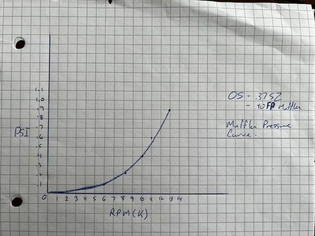
I stated yesterday that muffler pressure seemed low but the numbers today were better - I put a 4 oz tank in line to add a buffer and got better numbers on the manometer - I think it does a bit of a sampling average and the pulsating when hook directly must have effected it. It showed about .9 psi at WOT so one of the test I ran I closed in the bleed to mimic that pressure and it ran well at this setting.

I think you might think the pump is bigger than it is Bert - Its quite small... controller would be the same size and still runs of the receiver power with very little draw. The pump weighs 5 grams more than the solenoid and we don't need a crap trap. The needle will be a simple "restrictor" in the vent line tee when we know what size it must be. Overall I think the volume and weight will be less. It's a less precise system based on early test but seems less critical in setup also.
Will post video when processed...
I did get a "pressure curve" from the muffler tap today and its quite exponential as Bert expressed - Here is the quick graph of it..
I stated yesterday that muffler pressure seemed low but the numbers today were better - I put a 4 oz tank in line to add a buffer and got better numbers on the manometer - I think it does a bit of a sampling average and the pulsating when hook directly must have effected it. It showed about .9 psi at WOT so one of the test I ran I closed in the bleed to mimic that pressure and it ran well at this setting.
I think you might think the pump is bigger than it is Bert - Its quite small... controller would be the same size and still runs of the receiver power with very little draw. The pump weighs 5 grams more than the solenoid and we don't need a crap trap. The needle will be a simple "restrictor" in the vent line tee when we know what size it must be. Overall I think the volume and weight will be less. It's a less precise system based on early test but seems less critical in setup also.
Will post video when processed...
Last edited by Cat 1; 11-13-2022 at 02:11 PM. Reason: spelling

