


Electronic solutions to modifying glow engines of all sizes to gasoline
 11-13-2022, 02:36 PM
#1151
Senior Member
Thread Starter
0,9 psi is 62 mBar, correct? If so, that is pretty consistent with what I measured which was around 60 cm of water column.
That pump indeed is fairly small. What kind of service life expectation are we talking about? It is a brushed motor after all.
That pump indeed is fairly small. What kind of service life expectation are we talking about? It is a brushed motor after all.
 11-13-2022, 04:54 PM
#1152

They claim 100 hours of service life. They are typically used in medical equipment (BP measurement). They are very simple and efficient for air output for their size.. I have a couple of different styles inbound to see if there are internal and quality differences.
Here are the videos today...
First is the first curve run test - Still a bit rich in the middle but I have to tweak the software to add a bit more base exponential.. My test today showed that I can mimic the muffler curve but that too would probably be a bit thick in the middle -
Second is a short video of the idle - I went into the shop to get something and it idled like this for 2 minutes. Shot some video and was pleased to see it took throttle (albeit loaded up a bit)
Third is a run where I adjusted to mimic the Muffler pressure curve - I didn't work the curve at all just raised the pressure and closed the HS needle 2 clicks to adjust for the higher pressure (0.9PSI vs 0.6). Was playing a bit to try and clean up the mid range...
11-14-2022, 01:26 AM
#1153
Senior Member
Thread Starter
Chris, can I suggest something?
Can you make a visual indicator on your teststand for throttle movement? That makes it easier for us to judge how well the engine follows the throttle.
I am saying this, because a lot of videos out there (especially the ones from Morris Mini Motors) show engines that APPEAR to have a snappy throttle response until you enlarge to full screen and watch the relation between engine RPM and throttle movement.
Just a thought.
I myself am planning to fit a 2nd servo on the teststand that has no other function than to move a big dial indicator so the throttle position and movement are clearly visible in the video.
The following users liked this post:
TheEdge (11-14-2022)
11-14-2022, 11:02 AM
#1154
Chris, can I suggest something?
Can you make a visual indicator on your teststand for throttle movement? That makes it easier for us to judge how well the engine follows the throttle.
I myself am planning to fit a 2nd servo on the teststand that has no other function than to move a big dial indicator so the throttle position and movement are clearly visible in the video.
I haven't started into slow down setting on this one yet and I think it needs some work in this area.. With only RPM following it was OK but as soon as I introduced curves (bias) I could tell the pressure was leading the engine on certain occasions and needed a quick manual "lean adjustment" for a second to clear out before returning to the called for setting.
 11-16-2022, 05:24 AM
#1156
11-16-2022, 07:44 AM
#1158
Senior Member
Thread Starter
Years ago, I experimented with direct volumetric metering. I used an old window-washer pump (one with a rubber impeller, pretty much leak-free and fairly precise) and I used an old servomechanics as drive. That ittybitty tiny pump had to turn so unvelievably slow, it was a total PITA to control the fuel flow. It was unstable as heck, since a leaning out of the engine would cause a rise in RPM, which would in turn increase the air intake volume, but the fuel flow remained the same. Resulting in further leaning out.
There is no stability in such a system, it has to be actively stabilized. Which means control-loops with Proportional, integral and derivative action...
Here I was still controlling by hand:
11-16-2022, 02:46 PM
#1159


 11-16-2022, 06:16 PM
#1161
Thanks about right.. Remember the faster they go there clearance they like - I have a great article somewhere on modding the OS rod ends to survive IC ducted fan use - I will try to dig it up - Had an K&B .48 fan engine that I sent back because I thought they mis machined the Rod - very loose - Got it back with a nice note that the lower rod clearance was to spec and it had to be that way to survive- It ran well and lasted long - Sounded terrible turning it over though.
IT IS!!! IT IS!!!!!
 11-17-2022, 02:18 AM
#1164
Senior Member
Thread Starter
11-20-2022, 10:22 AM
#1165
i started playing with code a bit this morning. first was to add build options to disable the oled. and s.port and to enable the airpump...
next is to find an s.bus library and hopefully i can read additional channels without needing to modify the circuit. the hope is to repurpose the mixture channel input on pin 2 to read s.bus. this way we can add as many channels as we need such as air pump curve channel and even a few control channels to enable things like electronic choke, tuning of an electronic acceleration pump, etc. currently pin 0 is used for s.port but could possibly be repurposed for HOTT telemetry (just for you, chris) or even an engine rpm input (although my feeling is that rpm needs a new pin because if i start using rpm for calculations, i'd want to add it to the s.port telemetry which means the s.port pin needs to be separate from the RPM input pin. the same would apply if I add HOTT telemetry.)
chris, are you using the air pump for fuel pressure in conjunction with the solenoid or in place of the solenoid? my gut says we may want both but i'm not sure here since i haven't played with an air pump and don't currently have one.
Code:
//define build options here change to 0 to omit
boolean USE_SPORT =1;
boolean USE_OLED = 1;
boolean USE_AIRPUMP = 0;
chris, are you using the air pump for fuel pressure in conjunction with the solenoid or in place of the solenoid? my gut says we may want both but i'm not sure here since i haven't played with an air pump and don't currently have one.
 11-20-2022, 11:07 AM
#1167
11-20-2022, 02:42 PM
#1168
11-20-2022, 04:54 PM
#1169
I am working on a "package" for the unit to make it neater.. Should have something soon.
11-20-2022, 05:04 PM
#1170
Seems to me that the change in tank pressure, if we're talking about a controller based on tank pressure only, would have a fairly long time constant and wouldn't be able to keep up with the throttle changes the way the solenoid does, but a controller with both an air pump for fuel pressure and a solenoid valve might be an improvement over just a solenoid. Is it worth building a controller with mixture input to control the solenoid, rpm input to control the air pump, and throttle channel input to calculate an acceleration quantity of fuel to add?
11-20-2022, 07:30 PM
#1171
The pump is actually a quick responding setup Dave - Not as precise as the solenoid but very capable of keeping mixture in check - Im thinking the feedback from the rpm is helping in this regard but I have seen no delay issues with the response. Remember we are talking less than 1psi and the changes happen quick and very repeatable as its a positive displacement pump. I'm not sure if Acceleration function is needed with the air pump as I think by what I have seen it helps in this regard.
here are some pics of the module unit - Slightly bigger than a standard servo and about the same weight. simple hookup - one to ignition and one to open channel - air line to vent of tank.
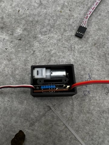
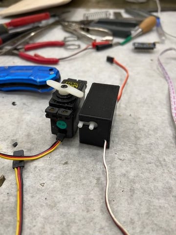
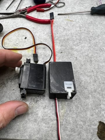
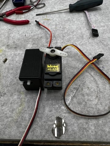
here are some pics of the module unit - Slightly bigger than a standard servo and about the same weight. simple hookup - one to ignition and one to open channel - air line to vent of tank.
11-20-2022, 07:49 PM
#1172
So you think it should be solenoid or air pump control. Okay, we should add rpm input to the xiao controller and have the option to use the air pump attached in place of the solenoid to make things simpler; build o e controller, use it with a solenoid or an air pump by flashing the proper firmware. I also wonder if the air pump could benefit from some more resolution than 215 steps.
So, I'll add rpm input to my controller and an option for the air pump in place of the solenoid. Do we need atmospheric compensation with the air pump? I think we do. I'll try to also add hott telemetry if I can find a hott library but I won't be able to test it so if I do, can I send you some coffee de to try?
This rewrite would be a few weeks out and probably happen in several steps to test on parts as I write them. I should order a few pumps too.
11-20-2022, 07:52 PM
#1173
Just read through my last post and didn't like how it seemed to imply that this is a full on replacement for the solenoid - I don't think it is... I think it will work well on some less critical installs (like my OS .37SZ) but I think the solenoid will still be beneficial in a lot of cases.
As it is built now if the power lead is plugged into a mid stick fixed output - It strictly acts like muffler pressure - the RC range 1000 - 2000 ms can add a 20% bias either way to do simple mixture adjustment but 1500 is the fixed curve set by the program with RPM input.
As it is built now if the power lead is plugged into a mid stick fixed output - It strictly acts like muffler pressure - the RC range 1000 - 2000 ms can add a 20% bias either way to do simple mixture adjustment but 1500 is the fixed curve set by the program with RPM input.
11-20-2022, 07:56 PM
#1174
Are you or will you be running this air pump/controller in conjunction with the solenoid and xiao controller? Is that something that is desirable? If so, we should consider adding the option to the xiao controller and make it to all one controller.
11-20-2022, 08:38 PM
#1175
On my Boxer I will be running this pump with the solenoid - The reason for chasing this pump solution was to eliminate the need to "restrict" the short 4 stroke exhaust to get a decent muffler pressure. An all in one solution would be great in this case and it would not require the bias adjustment of pressure. Just the rpm input to Pump output to mimic the muffler pressure. Mixture would be done by the system as it is now with the solenoid.