


TOP FLITE SPITFIRE BUILD


 07-17-2006 | 05:05 PM
#56
Here are the latest photos. I still have to finish work on the landing gears, make a more scale tail wheel strut, add a light to the rudder, and clearcoat. Then it's setup the gear and ballance. All the major paint and artwork are done. The end is in sight.
Scott
Scott
07-18-2006 | 12:33 PM
#57

Simply beautiful work, Saramos.
Your work is a fine bit of inspiration for my Mustang project.
Have you tested the RCV with that 4-blader? How much thrust
are you getting? I ask because I was thinking about my Mustang
project which will use an RCV SP engine, and it occured to me to
perform the first flight with a 2-blader, just to be safe. Then after
I'm sure that all the miscellaneous bugs are worked out of the plane,
I'll start to slowly reconfigure it with the 4-blade prop and then with
the whole fan cooling system that I envision.
07-18-2006 | 05:38 PM
#58
IL2,
Thanks for the comments.
I have only run the RCV on the bench with a 2 blade. I have not decided if I will use a 2 or the 4 blade for the maiden. I think I'll do some ground taxiing with the 4 blade and then decide.
Here's some photos of the cooling system I'll be experimenting with. I have not run the engine installed in the plane yet. I will post results when I test it out.
Scott
07-18-2006 | 06:10 PM
#59
So saramos, how will that fan get air to the engine?
It looks to me that it will be blowing the air into the engine block.
Or is it simply meant to push the air out as well as the exhaust.
Looking forward to the engine run results.
By the way, I mentioned this somewhere else:
I'll be doing a similary experimental fan cooling system, and I thought
that a good way to test the engine performance in a moving air stream
(without flying) would be to mount the fuselage to the top of my car.
Then I'd put thermocouples inside the engine area and run the cords
to a digital meter in the car, where I could observe the readings while
I drive on a desolate road. What do you think?
I also think I'll be doing the maiden flight with the cowl off, or with a
second cowl that has big air holes in it.
07-18-2006 | 08:24 PM
#61
The fan is blowing the air out of the cowl, creating a low pressure area behind the engine. I hope to be able to draw enough air between the spinner and cowl. There is about a 1/16" or so gap between them providing about a square inch of inlet. I'll start with that, then open a larger inlet as needed. I do have another third party fiberglass cowl waiting if needed.
Scott
Scott
07-19-2006 | 10:29 AM
#63
Want to see videos of the test setup, huh tfarmer?
Sure! Probably next year! LOL. I have a LOT of work to do before that.
Thanks for spelling out your cooling system, Saramos. I hope that it will
work great! Here's kinda what i have in mind for the Mustang:
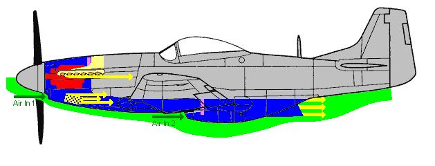
The green area is a representation of the pressure zone beneath the aircraft,
Blue is the path air will travel through the plane, yellow is air exitting the plane.
Air will enter below the nose, as it does in the real aircraft (and now I think I
will try to make it enter around the spinner too. Thanks Saramos!). I will try
to fit a fan behind the engine (purple) which will force air out of the exhaust
stacks. If it cannot be fit, then hopefully some air will be forced out naturally.
Similarly, there will be holes drilled in the chin (like on the real aircraft) that I
hope will remove some air. The rest will be sucked into a duct (which has a fan)
that will send it to the rear radiator. The radiator door will move with the throttle.
The duct will probably differ from this figure. It will travel above the wing to avoid
the ribs & spars.
As an alternative, I might install a fan underneath the engine to pull air in through
the hole pattern in the chin and blow it upwards at the engine.
One question about cooling in general:
I've read on these forums that it doesn't really matter how SMALL your inlet area is,
as long as your exit area is at least twice (or three) times as big. I can't seem to
wrap my head around that one. What do you guys think?
Sure! Probably next year! LOL. I have a LOT of work to do before that.
Thanks for spelling out your cooling system, Saramos. I hope that it will
work great! Here's kinda what i have in mind for the Mustang:
The green area is a representation of the pressure zone beneath the aircraft,
Blue is the path air will travel through the plane, yellow is air exitting the plane.
Air will enter below the nose, as it does in the real aircraft (and now I think I
will try to make it enter around the spinner too. Thanks Saramos!). I will try
to fit a fan behind the engine (purple) which will force air out of the exhaust
stacks. If it cannot be fit, then hopefully some air will be forced out naturally.
Similarly, there will be holes drilled in the chin (like on the real aircraft) that I
hope will remove some air. The rest will be sucked into a duct (which has a fan)
that will send it to the rear radiator. The radiator door will move with the throttle.
The duct will probably differ from this figure. It will travel above the wing to avoid
the ribs & spars.
As an alternative, I might install a fan underneath the engine to pull air in through
the hole pattern in the chin and blow it upwards at the engine.
One question about cooling in general:
I've read on these forums that it doesn't really matter how SMALL your inlet area is,
as long as your exit area is at least twice (or three) times as big. I can't seem to
wrap my head around that one. What do you guys think?
07-19-2006 | 11:30 AM
#64
Oh yeah, and here are the fans I'm using.
They are computer fans. 6cm diameter, 1cm thickness.
I got 5 of them for about $8 on ebay.
They are rated for a 12V power supply (eek!), but they kick on
at a lower speed with a voltage of 6V (four regular AA batteries).
This means that I'll probably be carying 6-8 batteries on my plane,
which will be on a seperate circuit to run the fans. It would be
standard to use AA cells, but I'm going to try AAA's because there
are significant weight savings and they have the same voltage rating.
It just means that I will have less run time.
The fans run on a current of 120 mA, while rechargable AAAs are
usually rated at about 1000 mAh. So to run 3 fans should get about
2.7 hours of run time. Do you guys concur?
(3)(120mA) / (1000 mAh) = 2.7 hour
Each rechargable AA or AAA gives 1.25V each.
Non-rechargable AAs and AAs give 1.5V each.
So an 8-pack of rechargable AAAs will deliver 10V
07-19-2006 | 11:38 AM
#65
Depending on where you are mounting the fan and batteries, the extra weight might be an advantage. A lot of warbirds require the addition of weight to the nose to balance. For example, in my case, I'll need around 2 lbs in the nose to balance. The added weight of the DF, controller and battery will offset some of the lead I will need to add.
Scott
Scott
07-19-2006 | 11:53 AM
#66
I'll have plenty of weight in the nose, me thinks 
I just bought a Zinger 4-blade prop (thank you ebay, once again!),
and was quite suprised by the weight of the assembly. I bet it's at
least 8 ounces. What 4-blader are you using, Saramos?
I fear that by the time I'm through, I will not only have a scale-looking
mustang, but also one with a scale power-to-weight ratio!
I actually have another P-51, an ARF that was given to me. It's not
very scale looking, so naturally I don't like it much :P. But, I think I
will make good use of it as a P-51 trainer so that I can get some
mustang stick time before sending my beauty in the air. I'll probably
have to put a lot of weight in that ARF to make it fly like the other.
The fans weigh next-to-nothing.
07-20-2006 | 01:26 AM
#68
For now, I am going with the 15.5 x 12 APC prop. I did the engine break in using an 18 x 12 2 blade APC.
I too have seen it suggested that the outlet should be 2 to 3 times the inlet. I guess the best answer for the size of the inlet is, big enough to get the cooling done. The ratio of inlet to outlet is to help insure good airflow. Inlet size will matter, but it depends on things such as what size engine, what type of flying, how lean it's run, type of fuel, so fort and so on. Regardless of the size of the inlet, the ratio should still be about 2:1 to 3:1. After reading as many threads I can find on engine cooling, it seems that 1 to 2 inches of inlet is what I find being described for a plane and engine in this size range. I'm going to try and start with the minimum inlet possible to avoid cutting more of the cowl than necessary. I don't think that the spinner gap would provide much airflow without the fan. I would think that with the fan, the effect of pulling air through would decrease the overall size needed for the inlet and outlet. If it works out with just the spinner gap, I'll be very very happy. The other area that I will be looking into are baffles. I have made a couple of baffles, but may make further adjustments. From what I've read, as well as what I've seen on full scale air cooled engines, it's best to keep the airflow as close to the cylinders as possible. I will probably work over my baffles again before testing. I'll be sure to take some photos.
With the chin scoop of the mustang, I think cooling would be a bit easier. One thought I had about the duct from the front to the scale radiator exhaust, are you going to have to make the duct removable in order to access the radio bay? I'll be very interested in your solution as my next project will be a TF P-51B. If the RCV works out well in the spit, I may use another in the P-51. The other route I am considering would be electric. I really do have a desire to turn 4 blades. Electric or the RCV are the only reasonable options I've seen.
Scott
07-20-2006 | 11:37 AM
#69
I guess the best answer for the size of the inlet is, big enough to get the cooling done.
So you've heard that 1-2 inches of inlet is enough huh? I hope
that rings true! If so, I'll be a very happy builder. I noticed on
some of the above spitfire pictures that there is a hole in the
cowl below the scale muffler stacks. Is that an inlet hole? I
almost didn't notice it at all.
I'll be adding a ramp from the chin scoop to the engine cylinder,
and then I'm leaning toward pulling air in from that hole pattern
on the side of the chin. A fan could sit nicely behind this chin
ramp in a flat position, and blow a nice amount of air on to the
cylinder.
Someone did mention the need to have a removable duct for
that reason, and I think they were dead-on right. I'm still not
sure how I will make the duct. Maybe some sort of thin plastic
(like transparency sheets) will work nicely. We'll see. But yeah,
I think I'll have to have sections of it that are removable. An
added complexity!
Have you seen the electric 5-bladed spitfire thread in the Warbirds
forum yet?
07-20-2006 | 07:00 PM
#70
The hole in the side of the cowl is to allow clearance for the throttle linkage. Even with it's design, the fit of the engine is tight in width, and the carb is mounted on the side with the glow plug on top and exhaust at the bottom. The full scale spit has a smaller bulge at that point and I may cover it with an oversized version. It should add a little more flow but not much. There is also a small cutout in the plastic that the stacks are mounted to allow for clearance for the carb itself.
Yes, I have seen the 5 blade spit. It's nice to see others attempting to go for a more scale prop. I know the APC blade that I am using doesn't come close to the scale outline of the real prop, but to me, it still looks a lot better than a 12 to 14" 2 blade. If he gets that 5 blade working well, it'll be a big head turner at the airfield.
Scott
07-21-2006 | 12:35 AM
#71
Saramos, are you going to use the starter crank on the side of the engine?
I guess getting to the engine when it is mounted would require another hatch.
Still, it looks like a nice way to start an engine, and much safer. Is there an
adaper of some kind that must be bought, or is it a standard size socket that
one could use with a power drill?
That 5-blade spitty is one of the best electric birds I've seen. In his video
you can hear the Merlin sound system. Very realistic sounding. If he can
demonstrate a 5-blade system, I might just have to build an electric Sea Fury.
We're on experimental ground with these 4 blades! Makes it fun and challanging.
07-21-2006 | 09:12 AM
#72
I plan on using a starter on the spinner. Using the starter adapter would, as you pointed out, require another hole in the cowl. I forgot to mention that I actually have another hole in the cowl for the needle adjustment.
Using the adapter from behind the prop is certainly safer. If you do go this route, the one drawback with using a drill is if the engine kicks back, the drive cap screw can unscrew. If you did use a drill, I would think that you could cut a driver from a standard alan. The adapter that you get from RCV is designed to fit the shaft of a starter. Also, when starting from the crank, you have to reverse the rotation because of the gearing. With a starter, you just connect your starter with the red clip to the black terminal on your battery and the black clip to the red terminal.
I think we are also blazing a trail in the area of fan assisted cooling too. (perhaps blazing isn't the word to use to describe cooling!)
Scott
07-21-2006 | 10:17 AM
#74
tfarmer, I'll be running my fans on an independent electrical circuit
with a seperate battery pack. I *might* run a set of landing lights
on the same battery pack. I think it would be risky to run these
supplemental systems off the receiver pack.
saramos, I don't understand why you start the engine "in reverse".
The prop spins in the same direction as most engines, right?
Sorry - confused.

