


High Flow fuel systems
 01-07-2016 | 04:38 PM
#1

I have all 3/16 Fuel tank fittings and 3/16 fuel tubing all the way to the UAT, should I take it down to 6mm for a tighter fit or just safety wire the 3/16 line to the BVM UAT then use 6mm to pump?
Thoughts?
OR 3/16 clunk/suction to 1/8 to UAT?
Thoughts?
OR 3/16 clunk/suction to 1/8 to UAT?
 01-07-2016 | 05:13 PM
#2


My Feedback: (39)
Since you are apparently plumbing your plane to accomodate a bigger turbine, I wouldn't use a BVM UAT at all. Read this: http://www.ultimate-jets.net/blogs/f...ing-cavitation
01-07-2016 | 05:49 PM
#4

Agree with bluelevel. UAT is marginal for even 120, due to the soft sides of the bottle, which start to collapse under vacuum, reducing the working area on the mesh trap. . You want a larger capacity and rigid sides. Take a look at GBR CATs. They come with larger fittings to accommodate 5/16 Tygon. You want to run 5/16 almost all the way to the pump if possible.
Apart from this, it is risky to safety wire the big tygon to a barb deigned for 1/4 Tygon. No matter how tight you get the wire, it may still pull in air at the fitting. Not worth the risk.
Also, be careful using 3/16 fittings inside the tank. You may need to go one tube size up to 7/32 (solder over the 3/16 to ensure a secure fit. If you are using 5/16 Viton inside the tank, you will need to go 1/4 to ensure snug fit. That's even with safety wire.
Last edited by TTRotary; 01-07-2016 at 05:52 PM.
01-07-2016 | 06:47 PM
#6
Agree with bluelevel. UAT is marginal for even 120, due to the soft sides of the bottle, which start to collapse under vacuum, reducing the working area on the mesh trap. . You want a larger capacity and rigid sides. Take a look at GBR CATs. They come with larger fittings to accommodate 5/16 Tygon. You want to run 5/16 almost all the way to the pump if possible.
Apart from this, it is risky to safety wire the big tygon to a barb deigned for 1/4 Tygon. No matter how tight you get the wire, it may still pull in air at the fitting. Not worth the risk.
Also, be careful using 3/16 fittings inside the tank. You may need to go one tube size up to 7/32 (solder over the 3/16 to ensure a secure fit. If you are using 5/16 Viton inside the tank, you will need to go 1/4 to ensure snug fit. That's even with safety wire.
Apart from this, it is risky to safety wire the big tygon to a barb deigned for 1/4 Tygon. No matter how tight you get the wire, it may still pull in air at the fitting. Not worth the risk.
Also, be careful using 3/16 fittings inside the tank. You may need to go one tube size up to 7/32 (solder over the 3/16 to ensure a secure fit. If you are using 5/16 Viton inside the tank, you will need to go 1/4 to ensure snug fit. That's even with safety wire.
clunk is http://www.dreamworksrc.com/catalog/Bvm-High-Flow-Clunk
fuel tubing so far is http://www.dreamworksrc.com/catalog/...uel-Tubing-316
I guess I have a NIB BVM UAT for sale..LMAO
So is it ok to use 3/16 on clunk lines/Vents all the way to "NEW Air trap" then hard fuel line to pump correct?
 01-07-2016 | 11:52 PM
#8
You are on the right path. 2 questions: what ID is your hard line from air trap to pump? Ideally, you want to keep the large ID all the way to, or as close the pump, as you can. Pumps are weak on the suction side and strong on the pressure side. Also, the harder the pump has to pull on the suction side due to restriction to deliver target flow on the pressure side, the more you increase the possibility of sucking an air bubble from a connection, or even causing the airtrap's membrane itself to cavitate (yes, this can also happen). For that turbine, you want to maintain 3/16 ID all the way to the pump if possible.
Second question: What is your clunk line? I just pulled Tygon out of a 2 year old fuel system and could not believe what poor shape it was in. Literally disintegrating. Use Viton if possible inside the tank. They make various sizes including 3/16 ID and McMaster Carr carries it. The BVM HF clunk is a great choice. Make sure all the internal passages have been thoroughly cleaned to remove brass particles. The tygon you selected is fine outside the tank and will last a long time as long as both side are not soaked in fuel.
Second question: What is your clunk line? I just pulled Tygon out of a 2 year old fuel system and could not believe what poor shape it was in. Literally disintegrating. Use Viton if possible inside the tank. They make various sizes including 3/16 ID and McMaster Carr carries it. The BVM HF clunk is a great choice. Make sure all the internal passages have been thoroughly cleaned to remove brass particles. The tygon you selected is fine outside the tank and will last a long time as long as both side are not soaked in fuel.
Last edited by TTRotary; 01-07-2016 at 11:55 PM.
01-08-2016 | 12:46 AM
#9
There is nothing wrong with a plastic bottle UAT, actually I'd use nothing else! If yours are sucking in then you have restrictions to the UAT and the plastic bottle is telling you that!
I use the MAP traps and they have std and Hi Flow versions. I use the Hi-Flow on any RXi JetCat and any turbine 180-250N
This is only part of it, clunk, clunk line and overflow fitting need to match the throughput!
Hard walled hopper tanks mask problems...not solve them! The daddy of composite tanks BV still uses a plastic hopper tank (they offer a high flow nipple version too) Don't you think if he thought hard walled was the way to go he would not have introduced one 10 years ago!!
This is a high flow MAP , the filler nipple is std size and feeds both 4.9mm
01-08-2016 | 02:14 AM
#11

My Feedback: (9)
Don't want to start a mess but we have been having problems with customers planes having flameouts with the CAT uat. I think dirk is going to try one on the test cell to look at what is going on.
Dirk will tell you use any other uat and your fine . I have used the bvm for a few years with out issues with a k180. The kingtech uat has also been perfect up to a 210.
Dirk still has more testing to do but in every case when a customer removes the CAT and installs some thing else engine runs perfect.
01-08-2016 | 02:14 AM
#12
My Feedback: (9)
Don't want to start a mess but we have been having problems with customers planes having flameouts with the CAT uat. I think dirk is going to try one on the test cell to look at what is going on.
Dirk will tell you use any other uat and your fine . I have used the bvm for a few years with out issues with a k180. The kingtech uat has also been perfect up to a 210.
Dirk still has more testing to do but in every case when a customer removes the CAT and installs some thing else engine runs perfect.
Dirk will tell you use any other uat and your fine . I have used the bvm for a few years with out issues with a k180. The kingtech uat has also been perfect up to a 210.
Dirk still has more testing to do but in every case when a customer removes the CAT and installs some thing else engine runs perfect.
01-08-2016 | 02:27 AM
#13
My Feedback: (9)
Don't want to start a mess but we have been having problems with customers planes having flameouts with the CAT uat. I think dirk is going to try one on the test cell to look at what is going on.
Dirk will tell you use any other uat and your fine . I have used the bvm UAT for years with out issues with a k180. The kingtech UAT has also been perfect up to a 210.
Dirk still has more testing to do but in every case when a customer removes the CAT and installs some thing else engine runs perfect. Also another friend showed me he was having problems using the smaller CAT in his aircraft. He thinks it was to small and that was the problem but removed it and installed a BVM UAT and all is well.
Last edited by gunradd; 01-08-2016 at 04:09 AM.
01-08-2016 | 02:44 AM
#14
My Feedback: (4)
Joined: Dec 2001
Posts: 2,341
Likes: 0
Received 0 Likes
on
0 Posts
From: Longwood ,
FL
Let me give you guys some info on the BVM High Flow UAT and the associated parts of our High Flow fuel system.
We have addressed the problem and updated the UAT and the remainder of the fuel system to allow high flow by increasing the fitting and line sizes.
Read this: http://www.bvmjets.com/Pages/Catalog/HiFlow.htm
Here's the system diagram which can be applied to most other airframes:http://www.bvmjets.com/images/K7300-32_34.pdf
We used my Ultra Bandit as a test bed for the system validation. With the new system, the P200 was very happy, and did not suffer from fuel starvation. The side walls of the plastic bottle did not suck in during full thrust operation when the flow demand is the highest.
Here's another article from the BVM website that is informative: http://www.bvmjets.com/Pages/Tips/FuelSystem.htm
Happy reading!
Last edited by Harley Condra; 01-08-2016 at 02:49 AM.
01-08-2016 | 04:15 AM
#15

My Feedback: (57)
There is nothing wrong with a plastic bottle UAT, actually I'd use nothing else! If yours are sucking in then you have restrictions to the UAT and the plastic bottle is telling you that!
I use the MAP traps and they have std and Hi Flow versions. I use the Hi-Flow on any RXi JetCat and any turbine 180-250N
This is only part of it, clunk, clunk line and overflow fitting need to match the throughput!
Hard walled hopper tanks mask problems...not solve them! The daddy of composite tanks BV still uses a plastic hopper tank (they offer a high flow nipple version too) Don't you think if he thought hard walled was the way to go he would not have introduced one 10 years ago!!
This is a high flow MAP , the filler nipple is std size and feeds both 4.9mm
I use the MAP traps and they have std and Hi Flow versions. I use the Hi-Flow on any RXi JetCat and any turbine 180-250N
This is only part of it, clunk, clunk line and overflow fitting need to match the throughput!
Hard walled hopper tanks mask problems...not solve them! The daddy of composite tanks BV still uses a plastic hopper tank (they offer a high flow nipple version too) Don't you think if he thought hard walled was the way to go he would not have introduced one 10 years ago!!
This is a high flow MAP , the filler nipple is std size and feeds both 4.9mm
I couldn't agree more. The BVM UAT will let you know that something is not setup correctly, or you have a vent obstruction by collapsing. In my opinion....still the simplest, and best UAT out there. I've seen some stuff out there that is just ridiculous overkill.
David
01-08-2016 | 04:18 AM
#16
My Feedback: (57)
And BTW I have been flying smaller engines without a UAT for a while now...................with absolutely no issues nor complications. Perhaps we should focus on eliminating UATs altogether by setting up and sizing our fuel systems properly (something that most model airplane companies just don't do correctly).
01-08-2016 | 04:30 AM
#17
Let me give you guys some info on the BVM High Flow UAT and the associated parts of our High Flow fuel system.
We have addressed the problem and updated the UAT and the remainder of the fuel system to allow high flow by increasing the fitting and line sizes.
Read this: http://www.bvmjets.com/Pages/Catalog/HiFlow.htm
Here's the system diagram which can be applied to most other airframes:http://www.bvmjets.com/images/K7300-32_34.pdf
We used my Ultra Bandit as a test bed for the system validation. With the new system, the P200 was very happy, and did not suffer from fuel starvation. The side walls of the plastic bottle did not suck in during full thrust operation when the flow demand is the highest.
Here's another article from the BVM website that is informative: http://www.bvmjets.com/Pages/Tips/FuelSystem.htm
Happy reading!
We have addressed the problem and updated the UAT and the remainder of the fuel system to allow high flow by increasing the fitting and line sizes.
Read this: http://www.bvmjets.com/Pages/Catalog/HiFlow.htm
Here's the system diagram which can be applied to most other airframes:http://www.bvmjets.com/images/K7300-32_34.pdf
We used my Ultra Bandit as a test bed for the system validation. With the new system, the P200 was very happy, and did not suffer from fuel starvation. The side walls of the plastic bottle did not suck in during full thrust operation when the flow demand is the highest.
Here's another article from the BVM website that is informative: http://www.bvmjets.com/Pages/Tips/FuelSystem.htm
Happy reading!
Harley, what is the internal setup of the High Flow BVM UAT? I have the regular one now and if it works then no need to upgrade it! LOL
Last edited by Dblex; 01-08-2016 at 04:40 AM.
01-08-2016 | 06:25 AM
#19
My Feedback: (4)
Joined: Dec 2001
Posts: 2,341
Likes: 0
Received 0 Likes
on
0 Posts
From: Longwood ,
FL
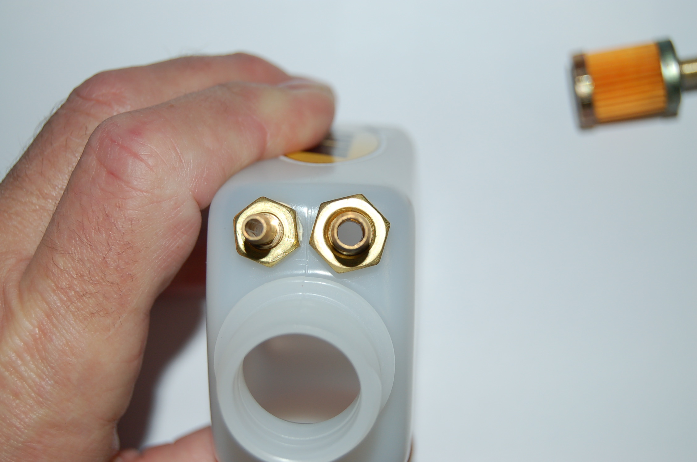
The internals were in no need of a change. The changes involved increasing the bore diameter of the feed and transfer fittings.
The feed fitting (The one on the UAT cap) was increased from .112 (2.84 mm) to .210 (5.33 mm) which is a 57% increase, and the bore diameter of the transfer fitting was increased from.102 to .175 (4.44 mm) which is a 52% increase. As shown in the photos, the feed fitting is now a barbed fitting. The filler fitting was not changed, for obvious reasons
.
Last edited by Harley Condra; 01-08-2016 at 06:30 AM.
01-08-2016 | 07:39 AM
#20

BVM does make a new hi flow version of their UAT, I think the best bang for your buck is the MAP, its a very nice UAT and I personally have ran a P200 on one with no issues. I have one of the new interairco hi-flow UATs in my latest jet but havent had a chance to test it. Looks great and deff has less restriction than the MAP just due to the style but my only worry is how the designed the port that connects to the tank, its not a open shot to the UAT like the normal style.
 01-08-2016 | 07:45 AM
#21
Joined: Jan 2007
Posts: 3,294
Likes: 0
Received 1 Like
on
1 Post
From: farnborough, , UNITED KINGDOM
CAT update.
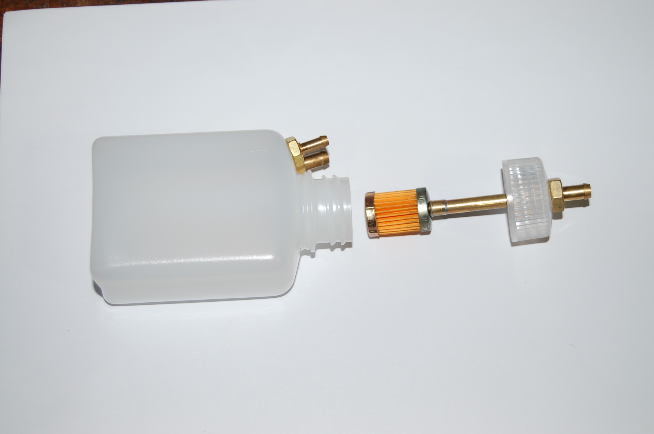
The CAT uses a PPF (pleated paper filter), designed for use in fuel systems as its central pickup, compared to many other UAT products this filter is relatively large in relation to the container it is housed in. This is to make sure the surface area of the filter is as large as it can be which in turn removes the chances of cavitation which can occur when fuel restrictions are present.
The system when new is supplied dry, once fuel is added the filter takes on a characteristic where it freely allows fuel to pass through even during intermittent exposure to air (possibly during energetic flying and when the main tank is low). On the flip side if the fuel level in the CAT is allowed to drain down to below the PPF for extended periods, i.e. during transportation, travel or storage air will slowly bleed through the fuel soaked filter and into the PPF.
When the turbine next runs this air will at some point pass through to the turbine. The method as Oli states (in a new thread on this forum) is to run the turbine and purge the CAT whilst tapping it to dislodge any air that may be inside the filter.
The PPF is brilliant at stopping air passing through it during normal flying use but when air does bleed into it during situations mentioned above, its equally brilliant at keeping it inside!
As a rule of thumb once you fill your CAT leave the CAT fully fuelled at all times, it's how it was designed to be, any air which enters the CAT tank during filling with fuel can be removed by reversing your filling pump for a second or two when the system is full to suck out the air (make sure fill barb is uppermost).
Safe flying.
marcs
 01-08-2016 | 08:10 AM
#23
My Feedback: (9)
Great info Marc.
I see so many people out their that defuel their plane after flight... Drives me crazy. nothing worse for any UAT then to sit dry after being in fuel.
I see so many people out their that defuel their plane after flight... Drives me crazy. nothing worse for any UAT then to sit dry after being in fuel.
CAT update.
The CAT uses a PPF (pleated paper filter), designed for use in fuel systems as its central pickup, compared to many other UAT products this filter is relatively large in relation to the container it is housed in. This is to make sure the surface area of the filter is as large as it can be which in turn removes the chances of cavitation which can occur when fuel restrictions are present.
The system when new is supplied dry, once fuel is added the filter takes on a characteristic where it freely allows fuel to pass through even during intermittent exposure to air (possibly during energetic flying and when the main tank is low). On the flip side if the fuel level in the CAT is allowed to drain down to below the PPF for extended periods, i.e. during transportation, travel or storage air will slowly bleed through the fuel soaked filter and into the PPF.
When the turbine next runs this air will at some point pass through to the turbine. The method as Oli states (in a new thread on this forum) is to run the turbine and purge the CAT whilst tapping it to dislodge any air that may be inside the filter.
The PPF is brilliant at stopping air passing through it during normal flying use but when air does bleed into it during situations mentioned above, its equally brilliant at keeping it inside!
As a rule of thumb once you fill your CAT leave the CAT fully fuelled at all times, it's how it was designed to be, any air which enters the CAT tank during filling with fuel can be removed by reversing your filling pump for a second or two when the system is full to suck out the air (make sure fill barb is uppermost).
Safe flying.
marcs
01-08-2016 | 08:53 AM
#24
The paper style like the MAP using is supposed to be kept wet, if not the fuel will evaporate and the oil left will eventually gum up the paper.
it may just be me but I feel the biggest mistake people make is not using large enough fittings on the Vent side of the system. The fuel pressure from pulling fuel through system really grows when you restrict how much air you can pull into the tank. If the fuel leaving the tank is overcoming the the ability to pull air in things start to go bad.
it may just be me but I feel the biggest mistake people make is not using large enough fittings on the Vent side of the system. The fuel pressure from pulling fuel through system really grows when you restrict how much air you can pull into the tank. If the fuel leaving the tank is overcoming the the ability to pull air in things start to go bad.
Last edited by FenderBean; 01-08-2016 at 09:01 AM.


