


F-16XL ARF by Global Knight Models from Global Jet Club
 04-09-2021, 06:47 PM
#101

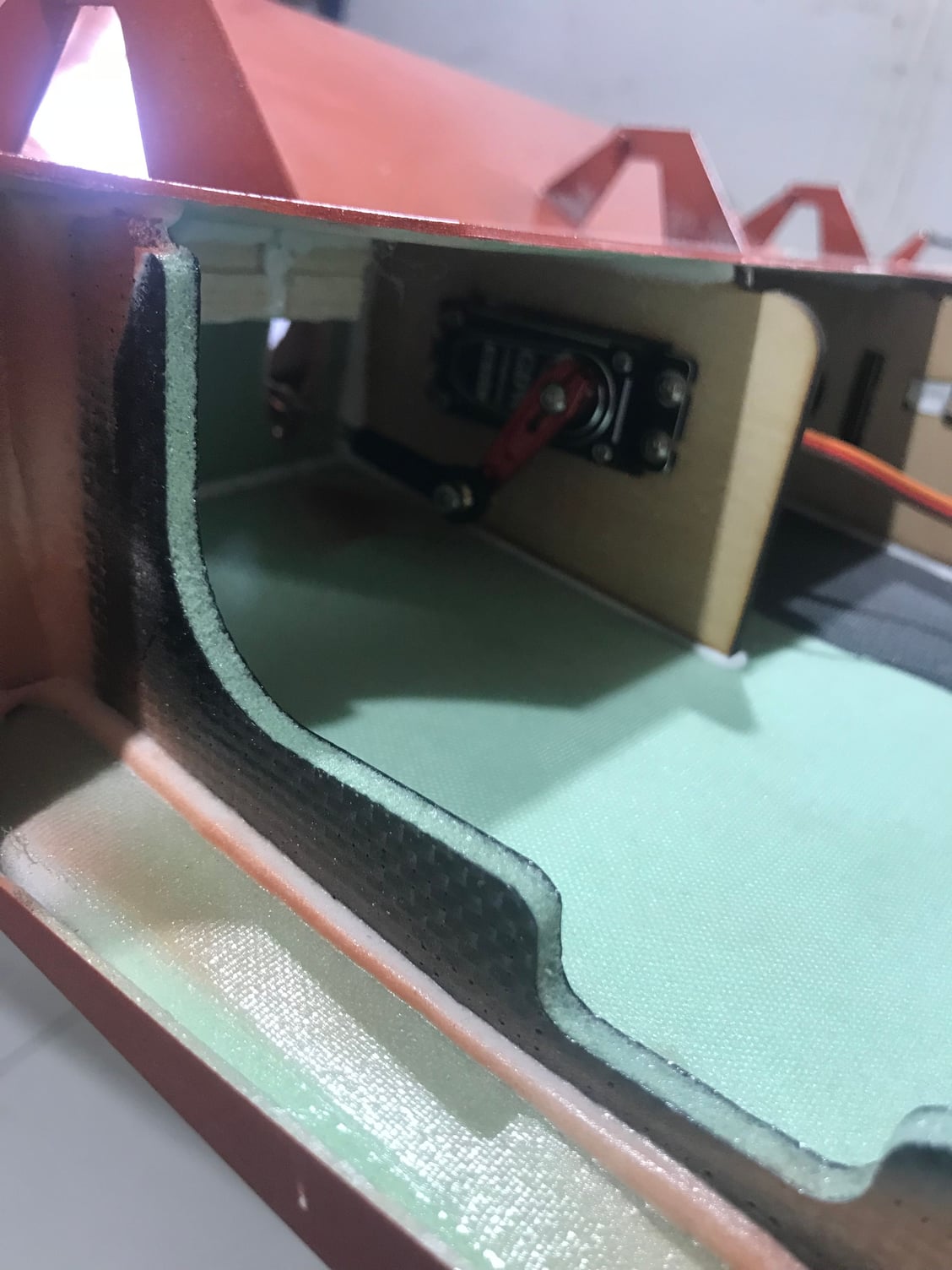
Working on the second xl I threw mine together to get flying but taking my time with f900 xl here are a few pictures of the carbon beef up on the strakes. I made a C channel between the 2 mounts and tied it in with the fiber glass tubes. Altho I still think this is in needed it gives my buddy piece of mind.

 04-10-2021, 04:50 PM
#102
Thread Starter
My Feedback: (20)
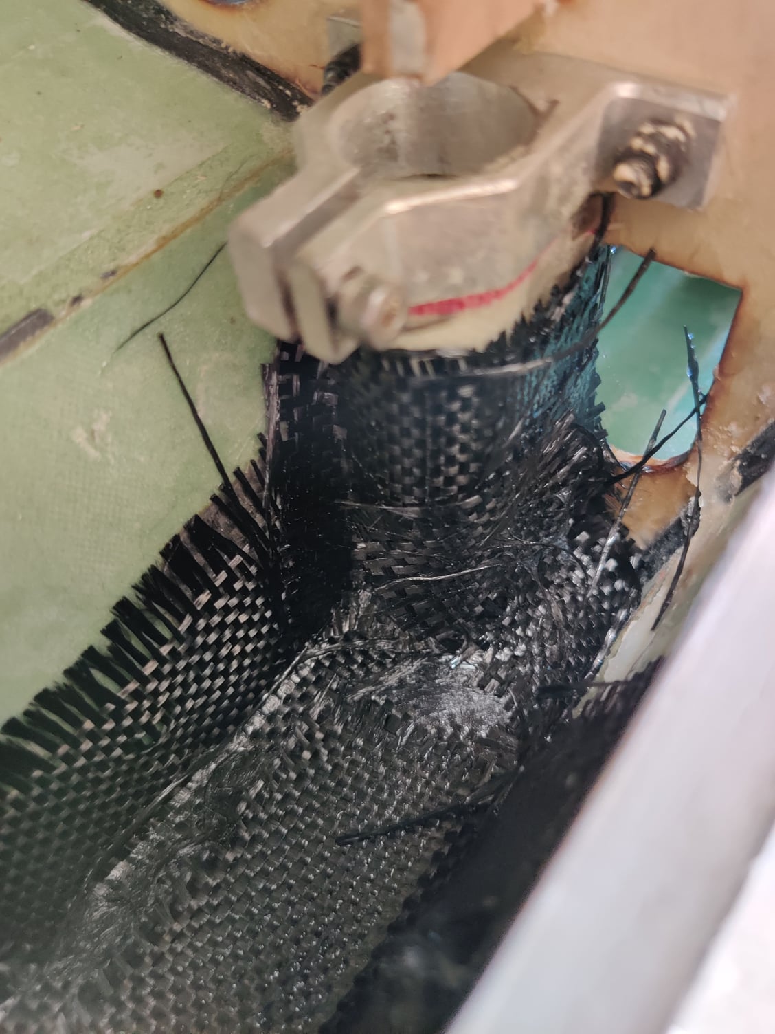
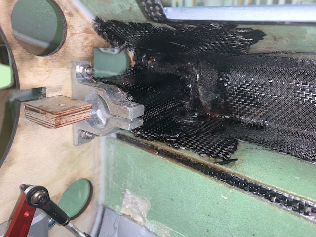
Carbon fiber reinforcements of wing tube sleeves and wing box.
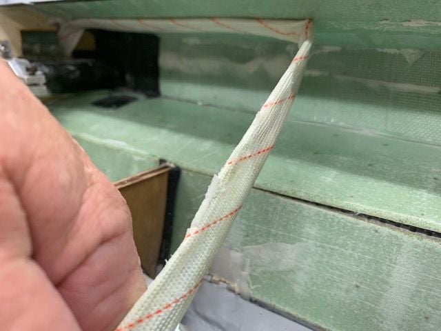
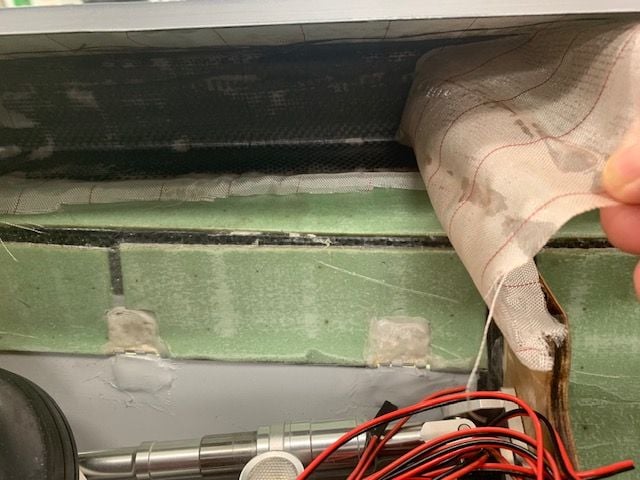
I think the factory wing join system was probably strong enough but I wanted to add some insurance just in case. I basically copied the work and ideas that Josh used for F900's F-16XL build. First I removed the servo wires that were pre installed in a fabric tube above the saddle fuel tank compartments.
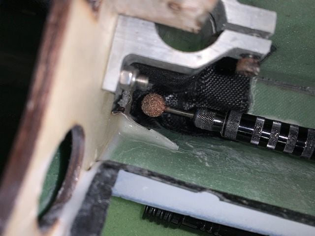
Ball grinder use to clean up the left over epoxy from the wire sleeves
This was the factory install with only one piece of CF cloth holding the sleeve in place. My goal is to make a carbon cage above and below each wing tube sleeve and then connect the two wing formers with a carbon C channel inside the fuse wing root forming a wing box inside the fuse skin. Then a plywood sub former will go above the tube sleeve to join sleeve to the CF reinforced fuse skins. This should lock the sleeve firmly to the former and help spread wing loads through the CF reinforced fuse skins.
First step was to lap a strip of CF over the tube sleeve tying it to the former so that positive G can not pull the tube up off the former.
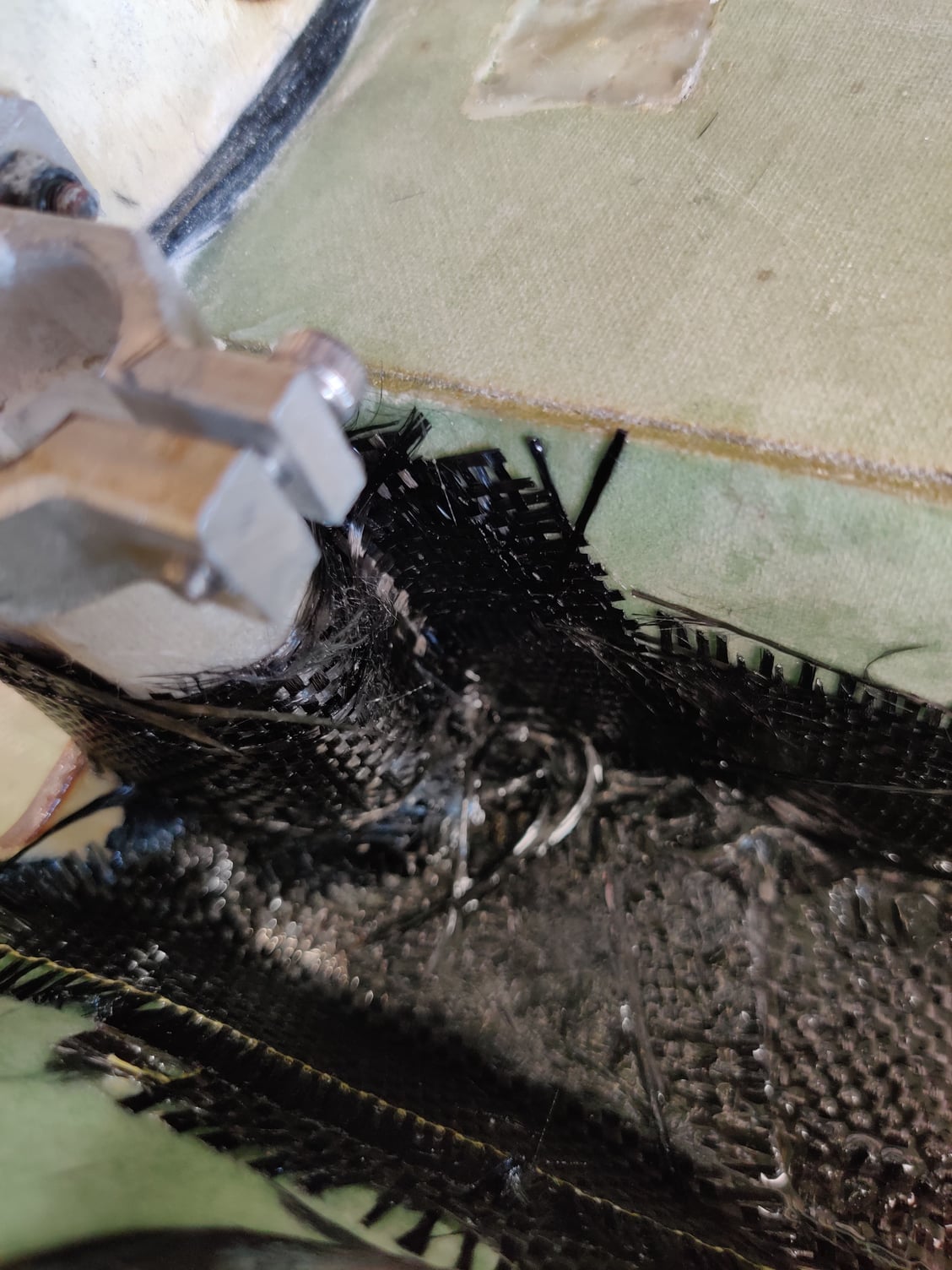
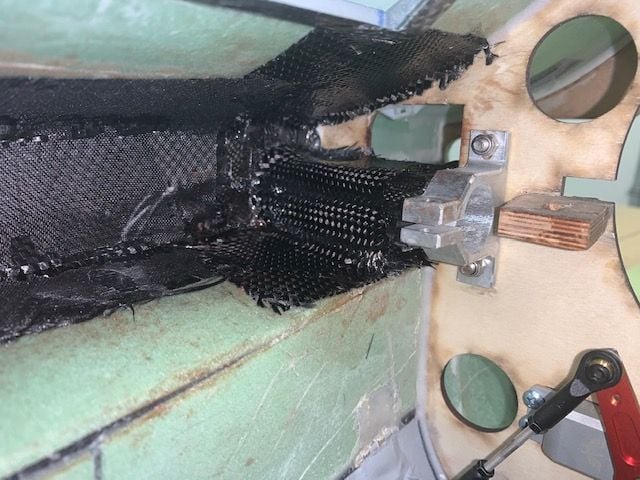
Next CF is applied above and below the tube sleeve to spread the wing tube loads into the reinforced fuse skin. I forgot to take a photo of the bottom pieces of CF below the tube sleeves.
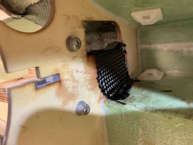
Next two strips of CF were applied to form a C channel in the wing root joining front and back wing tube sleeves. Peel ply was applied to help hold the CF in place.
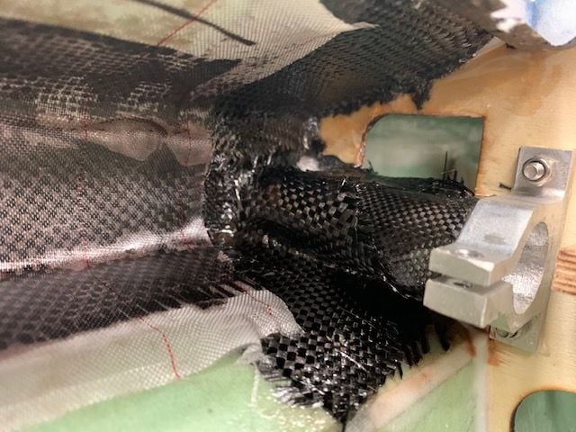
I first planned to put a plywood sub former below each wing tube sleeve but this became impractical after the CF was applied to the lower fuse skin. So I decided to wrap another piece of CF over the sleeve to tie it to the lower fuse skin after the peel ply was removed.
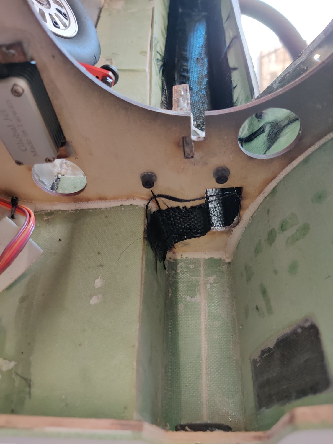
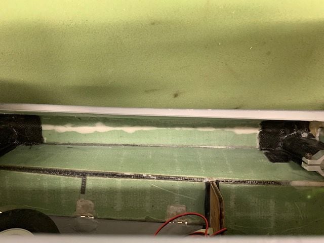
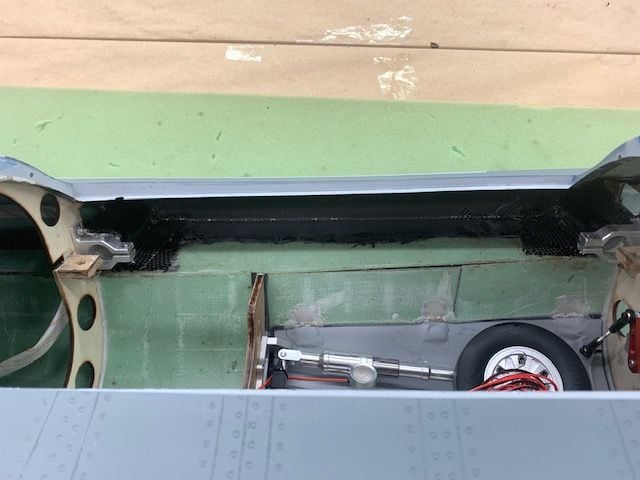
Peel ply removed after epoxy cured left a pretty flat CF surface.
The last CF strip was lapped over the tube sleeve to tie the sleeve down to the lower CF fuse skin.
Next will be a plywood sub former above the tube sleeve to connect the upper fuse skin with the tube sleeve to transmit wing load into the reinforced upper fuse skin.
Not perfect but will provide some insurance. Hopefully the GK factory can provide and more robust wing joint system in future production runs.
I think the factory wing join system was probably strong enough but I wanted to add some insurance just in case. I basically copied the work and ideas that Josh used for F900's F-16XL build. First I removed the servo wires that were pre installed in a fabric tube above the saddle fuel tank compartments.
Ball grinder use to clean up the left over epoxy from the wire sleeves
This was the factory install with only one piece of CF cloth holding the sleeve in place. My goal is to make a carbon cage above and below each wing tube sleeve and then connect the two wing formers with a carbon C channel inside the fuse wing root forming a wing box inside the fuse skin. Then a plywood sub former will go above the tube sleeve to join sleeve to the CF reinforced fuse skins. This should lock the sleeve firmly to the former and help spread wing loads through the CF reinforced fuse skins.
First step was to lap a strip of CF over the tube sleeve tying it to the former so that positive G can not pull the tube up off the former.
Next CF is applied above and below the tube sleeve to spread the wing tube loads into the reinforced fuse skin. I forgot to take a photo of the bottom pieces of CF below the tube sleeves.
Next two strips of CF were applied to form a C channel in the wing root joining front and back wing tube sleeves. Peel ply was applied to help hold the CF in place.
I first planned to put a plywood sub former below each wing tube sleeve but this became impractical after the CF was applied to the lower fuse skin. So I decided to wrap another piece of CF over the sleeve to tie it to the lower fuse skin after the peel ply was removed.
Peel ply removed after epoxy cured left a pretty flat CF surface.
The last CF strip was lapped over the tube sleeve to tie the sleeve down to the lower CF fuse skin.
Next will be a plywood sub former above the tube sleeve to connect the upper fuse skin with the tube sleeve to transmit wing load into the reinforced upper fuse skin.
Not perfect but will provide some insurance. Hopefully the GK factory can provide and more robust wing joint system in future production runs.
04-11-2021, 11:35 AM
#104
Thread Starter
My Feedback: (20)
Installing sub formers over wing tube sleeves
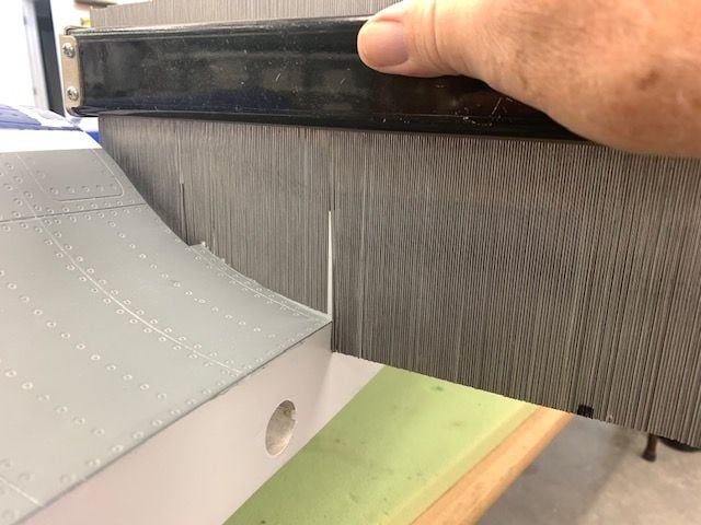
Pattern maker used to get the top of the fuse curved shape
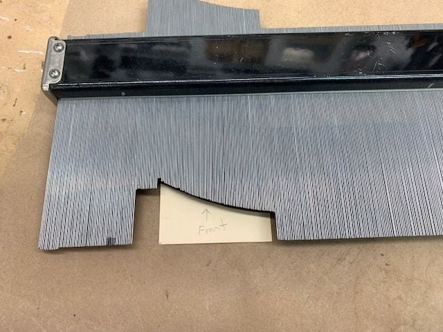
Shape transferred to cardboard template
Spent about 30 min grinding, filing, and sanding all the CF splinters and spikes around the edges of the CF layup. Nasty stuff after the epoxy cures on it. Then did the cardboard pattern test fit
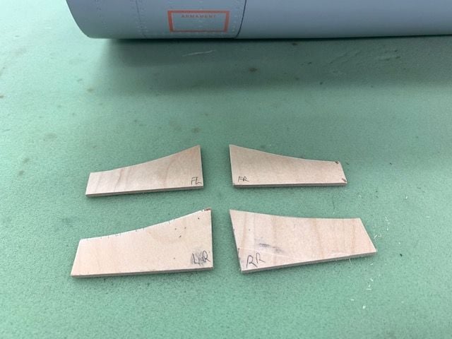
Plywood sub formers cut
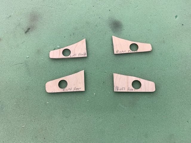
Final shapes after test fitting each sub former. Holes drilled for servo wires
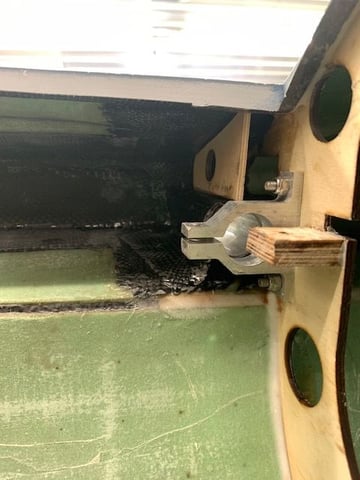
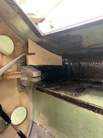
Formers tacked in with 5 min epoxy. Right rear shown here.
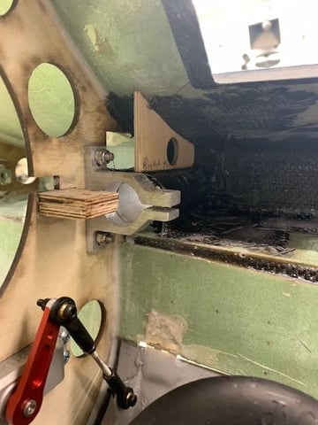
RIght front here
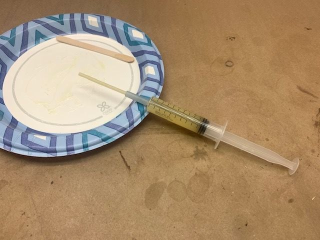
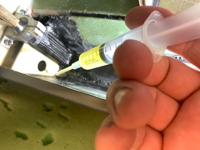
Syringe filled with West System Six10 epoxy. Extended applicator made from a piece of plastic tubing and silicon fuel tube
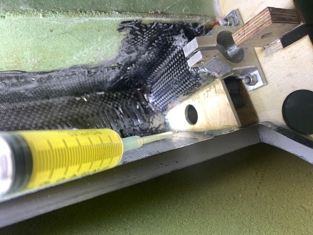
It proved impossible to get between the sub former and the wing former so I had to settle for an epoxy fillet just on one side
Now the wing tube sleeves are securely locked between the CF reinforced fuse skins and the main former. If I pull 20G some day the wing may break off but I'm sure the tube sleeve and tube will still be attached to the fuse!
Pattern maker used to get the top of the fuse curved shape
Shape transferred to cardboard template
Spent about 30 min grinding, filing, and sanding all the CF splinters and spikes around the edges of the CF layup. Nasty stuff after the epoxy cures on it. Then did the cardboard pattern test fit
Plywood sub formers cut
Final shapes after test fitting each sub former. Holes drilled for servo wires
Formers tacked in with 5 min epoxy. Right rear shown here.
RIght front here
Syringe filled with West System Six10 epoxy. Extended applicator made from a piece of plastic tubing and silicon fuel tube
It proved impossible to get between the sub former and the wing former so I had to settle for an epoxy fillet just on one side
Now the wing tube sleeves are securely locked between the CF reinforced fuse skins and the main former. If I pull 20G some day the wing may break off but I'm sure the tube sleeve and tube will still be attached to the fuse!
Last edited by Viper1GJ; 04-11-2021 at 04:17 PM.
The following users liked this post:
patf (04-13-2021)
04-12-2021, 04:37 PM
#105
Thread Starter
My Feedback: (20)
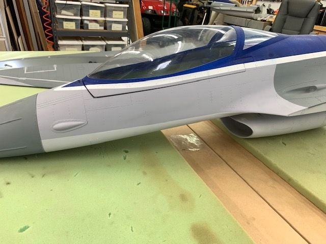
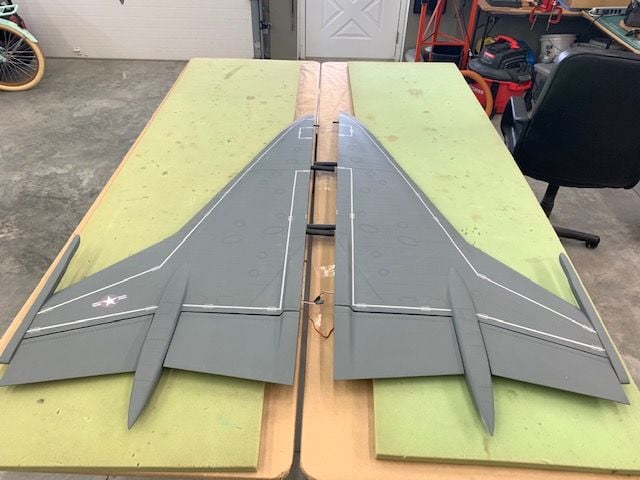
Repainting fuse
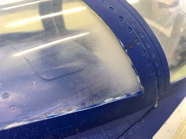
When preparing to repaint the cream color I noticed some overspray on the rear canopy from the factory paint job. Does anybody have recommendations for cleaning off the overspray with out messing up the canopy plastic?
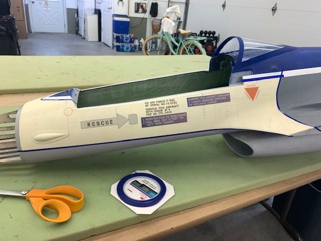
Masking off the cream color areas with 3M blue fine line vinyl tape
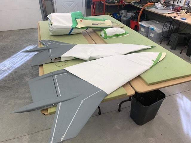
Masking prep complete, ready to spray new grey paint
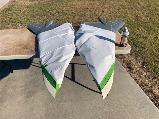
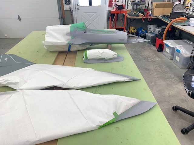
WIng first

Canopy next
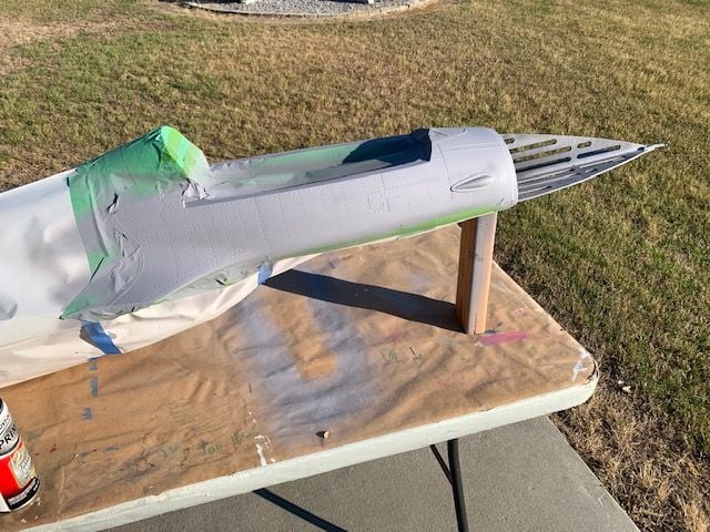
Forward fuse last
It took far longer to mask everything than to spray it.
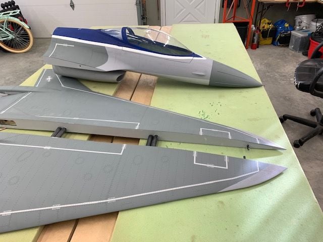
It's not a "cream puff" anymore! Grey color came out OK. My lines were better than the factory lines.
Josh reminded me that the grey lines were soft lines not hard lines so I may hit the grey on grey lines with an airbrush later to make the color separation lines soft. Just need more time to work on it.
Hope the decals come soon.
When preparing to repaint the cream color I noticed some overspray on the rear canopy from the factory paint job. Does anybody have recommendations for cleaning off the overspray with out messing up the canopy plastic?
Masking off the cream color areas with 3M blue fine line vinyl tape
Masking prep complete, ready to spray new grey paint
WIng first
Canopy next
Forward fuse last
It took far longer to mask everything than to spray it.
It's not a "cream puff" anymore! Grey color came out OK. My lines were better than the factory lines.
Josh reminded me that the grey lines were soft lines not hard lines so I may hit the grey on grey lines with an airbrush later to make the color separation lines soft. Just need more time to work on it.
Hope the decals come soon.
The following users liked this post:
drfred58809 (04-12-2021)
The following users liked this post:
Viper1GJ (04-12-2021)
04-12-2021, 05:43 PM
#107
Thread Starter
My Feedback: (20)
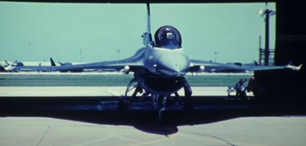
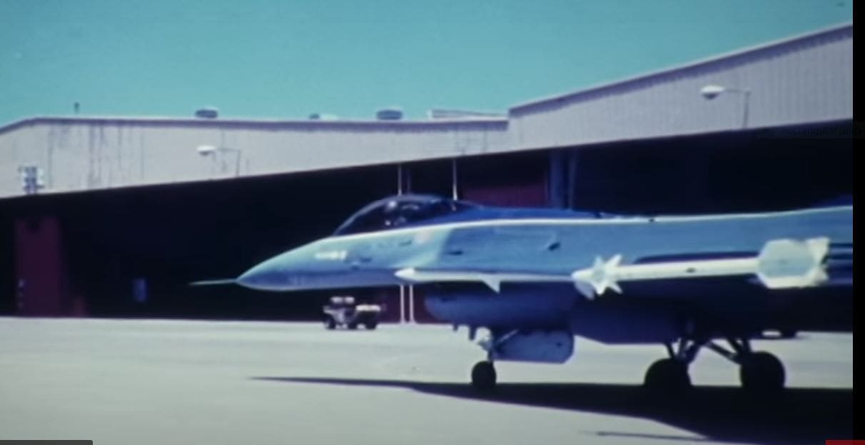
While looking for photos of the F-16 XL paint scheme as I work on the repaint I found this video. A little boring with no sound but it has some good side and top views in the GD prototype paint scheme. You can clearly see the soft grey color separation done with a spray gun. I may try to make mine look a little more like this.
Last edited by Viper1GJ; 04-12-2021 at 05:48 PM.
The following users liked this post:
drfred58809 (04-12-2021)
04-12-2021, 07:48 PM
#108
My Feedback: (2)
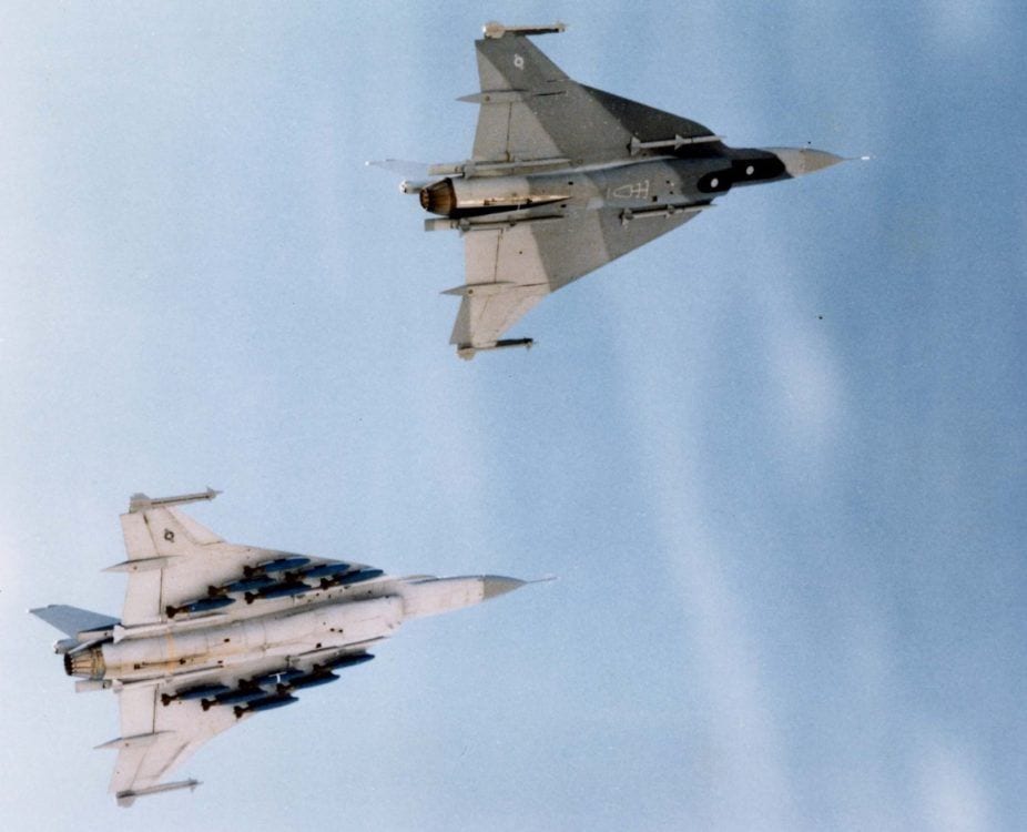
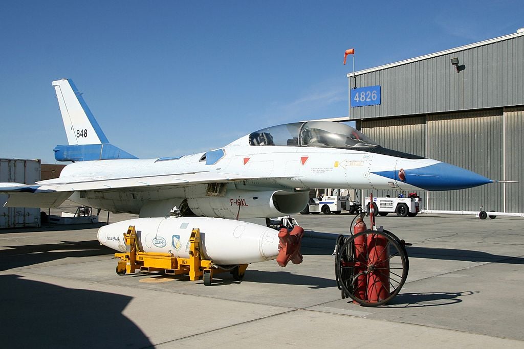
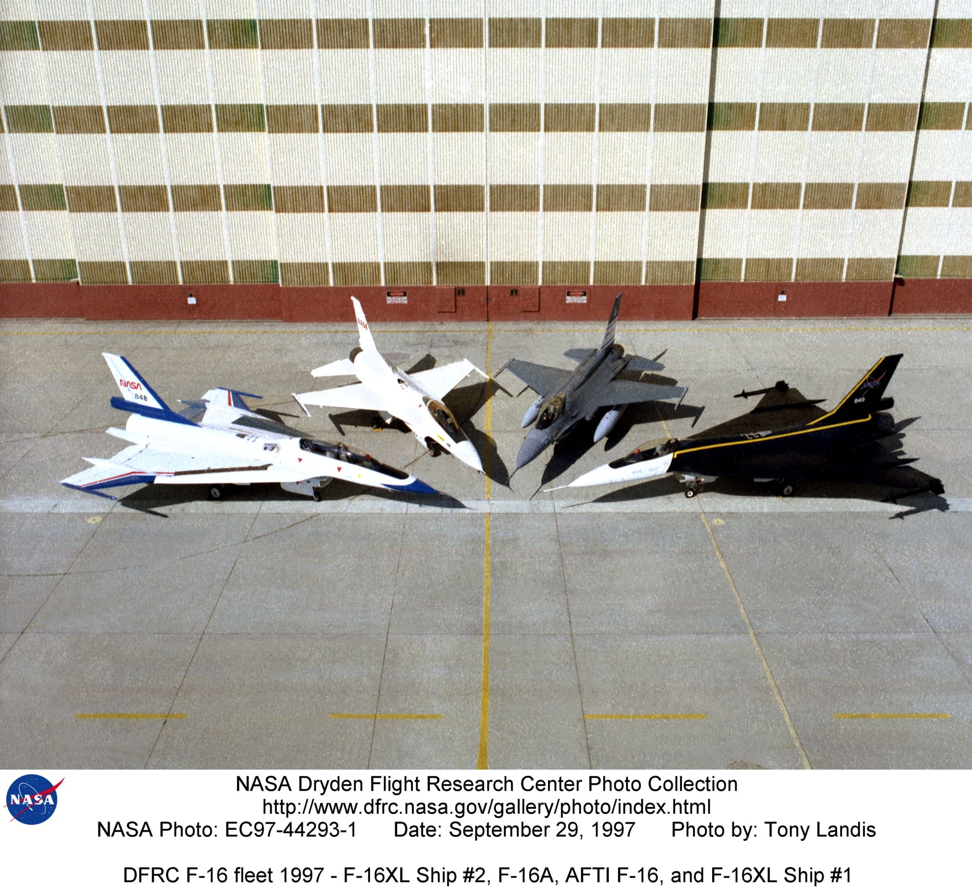
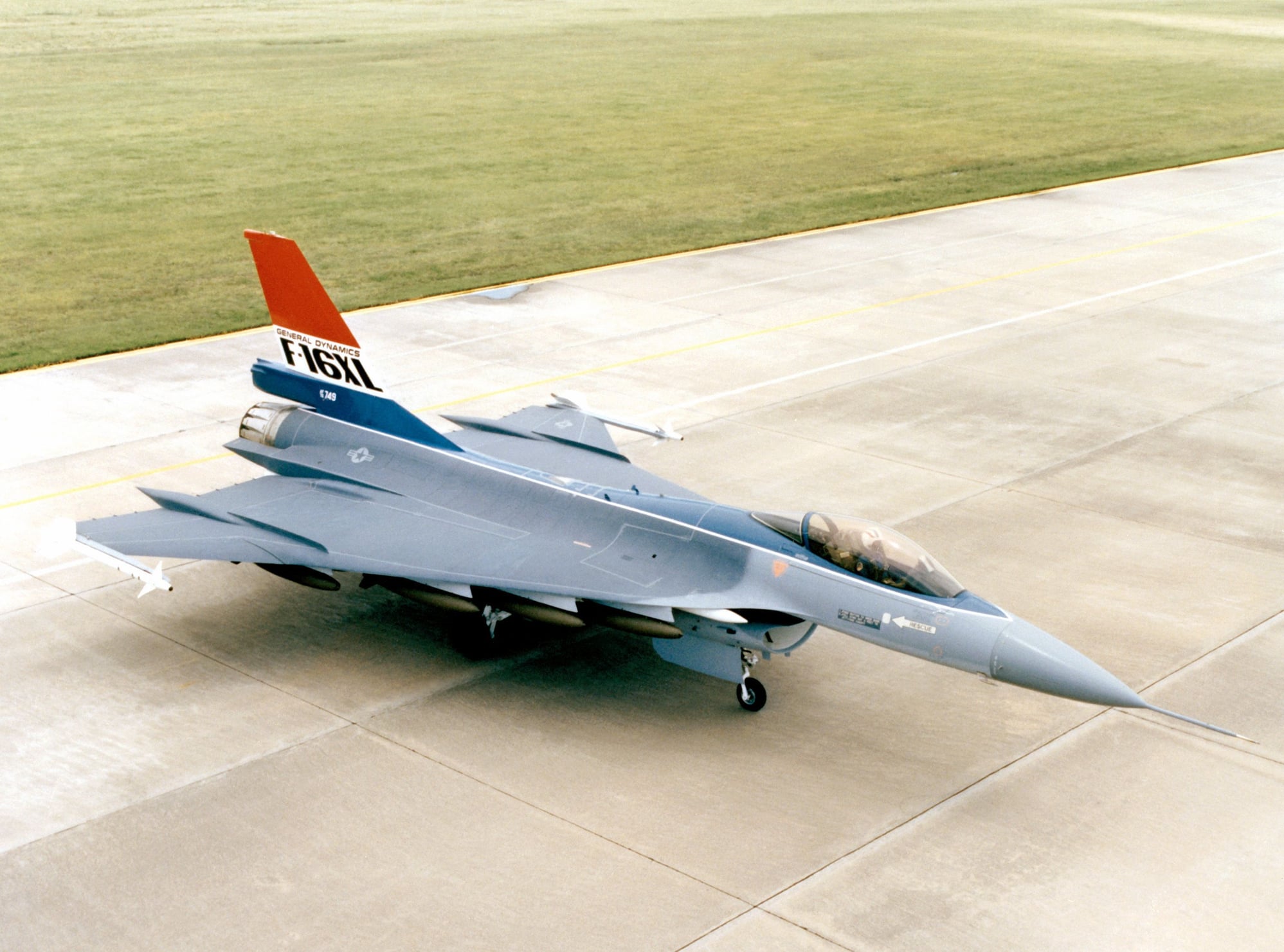
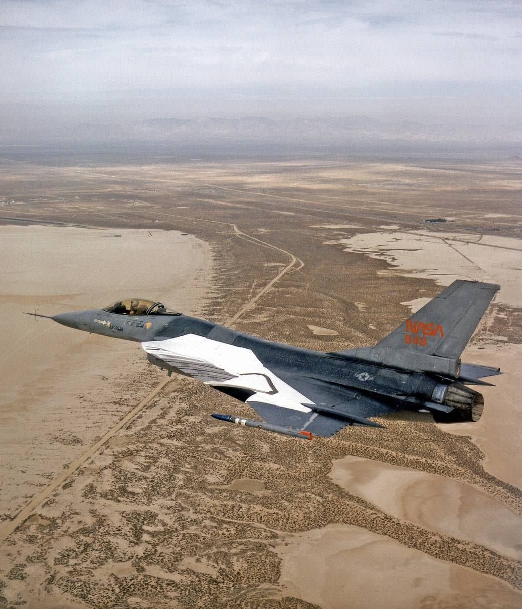
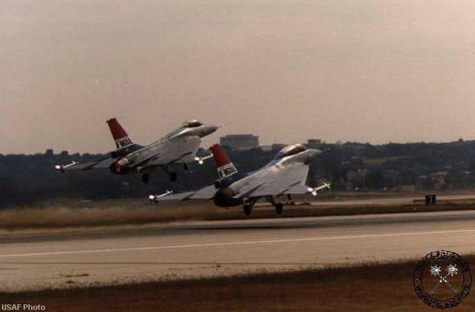
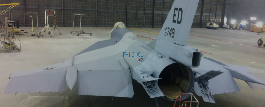
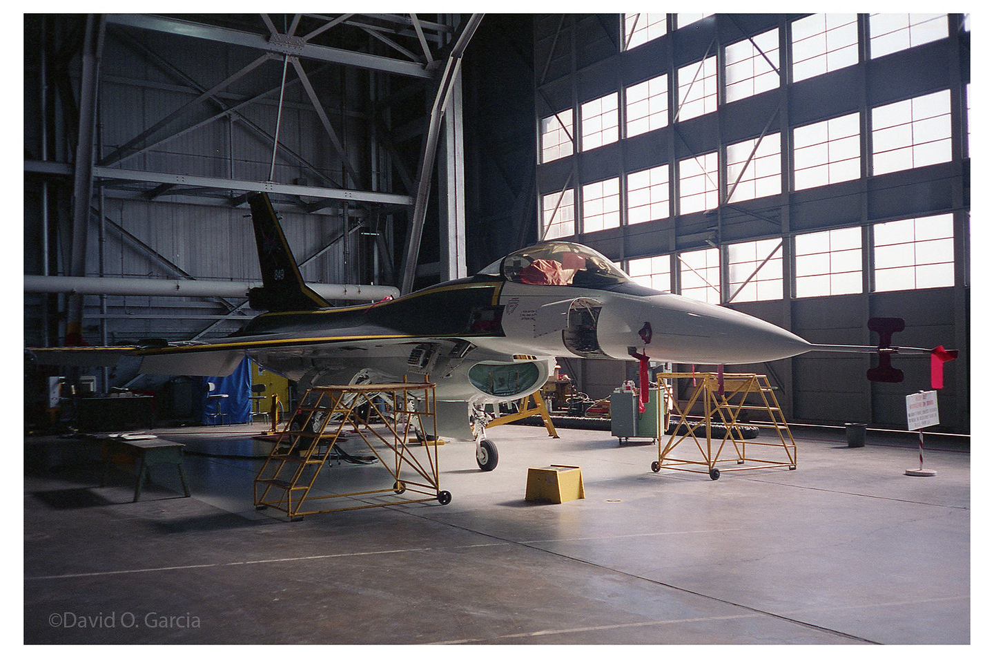
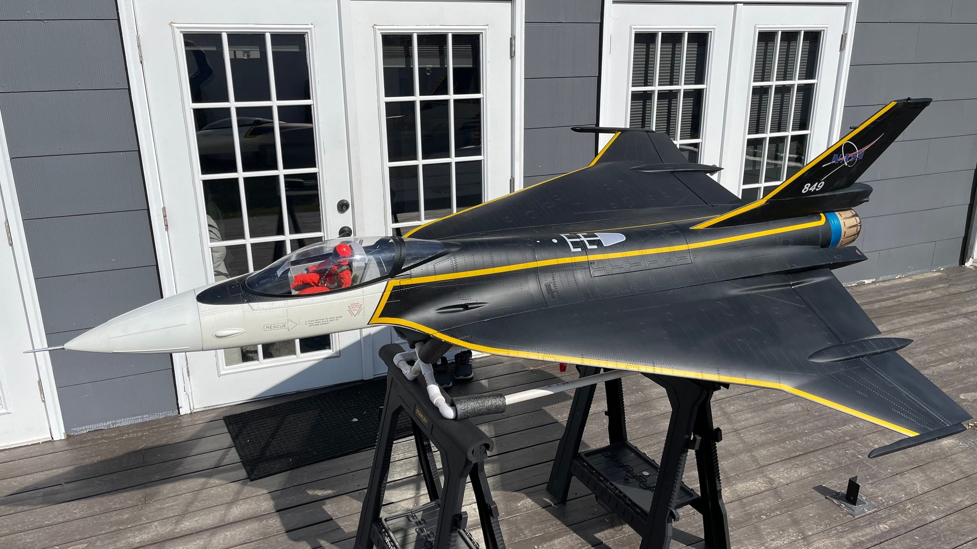
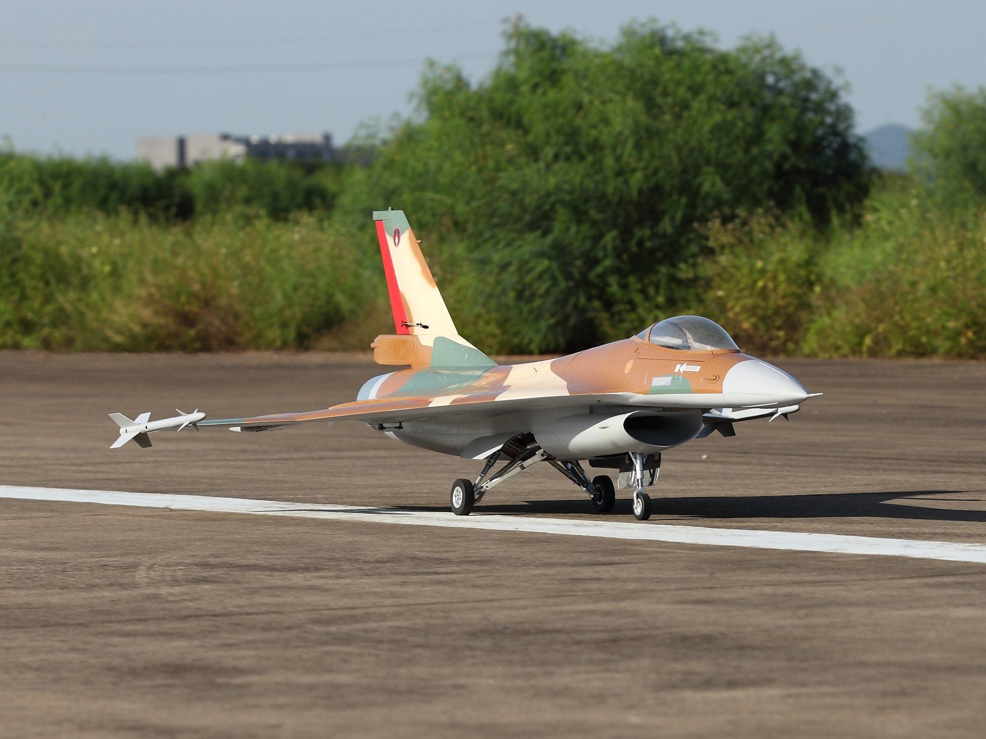
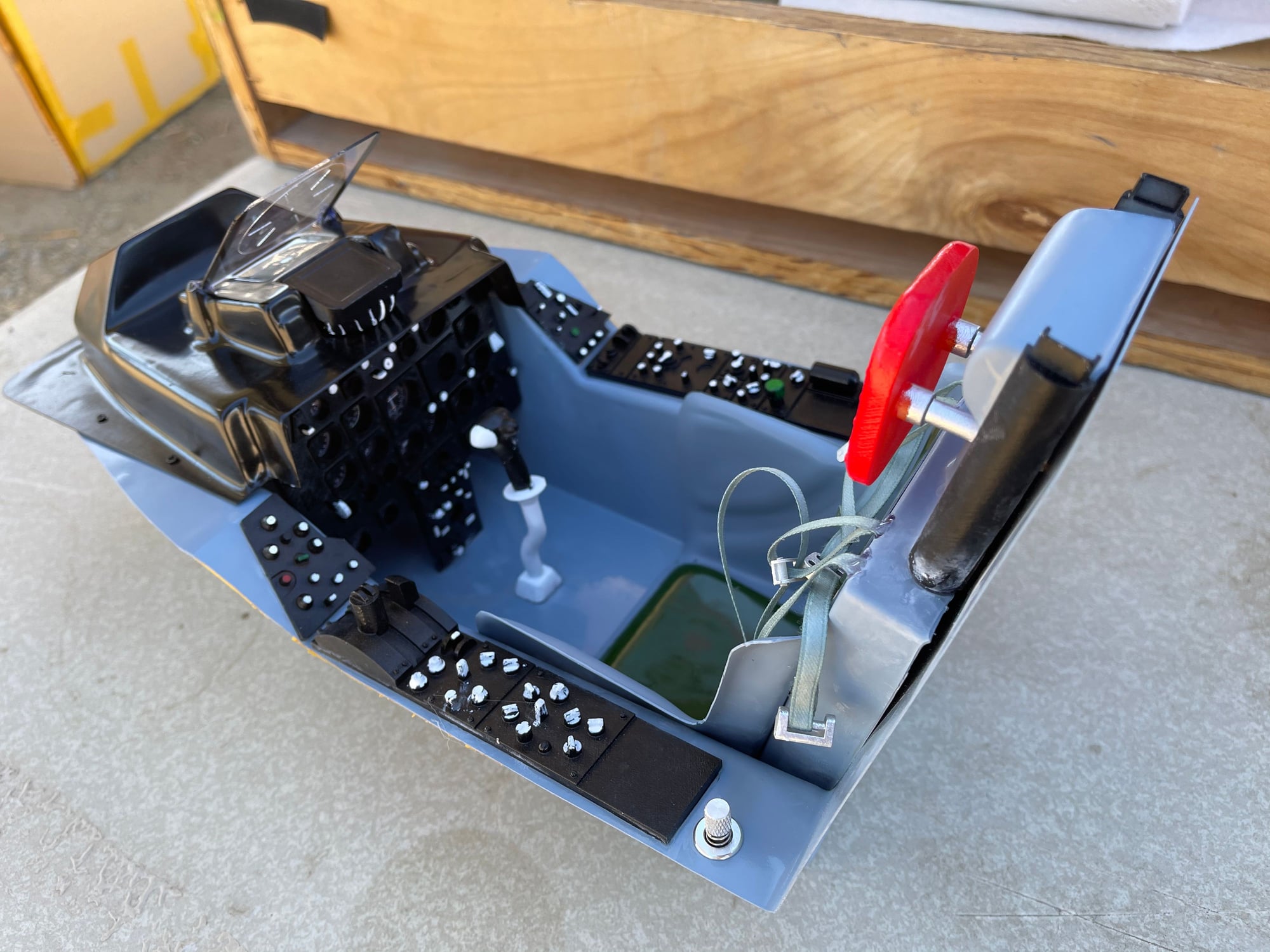
There is all kinds of interesting XL pictures and lots of information about them..here is just another sample of XL configurations and schemes.
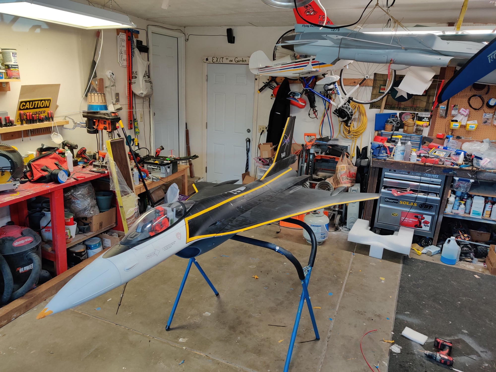
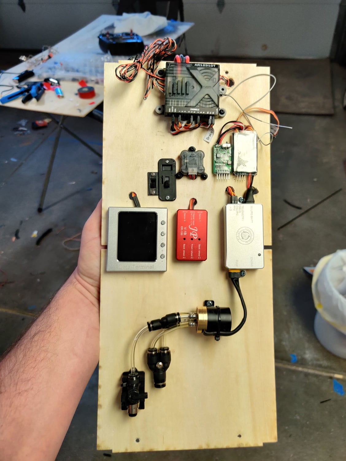
And my XL is about ready and now sits in my not flown hangar of jets, just some radio programing left and when the cold weather passes this week it will be ready for its 1st flight.
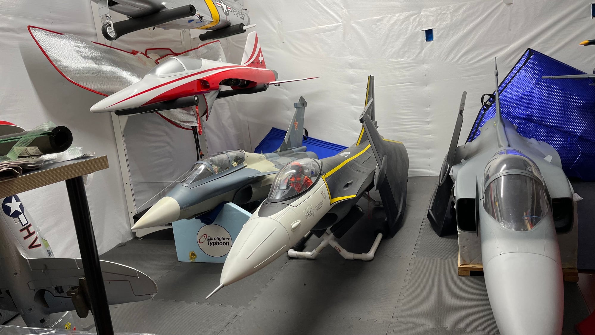
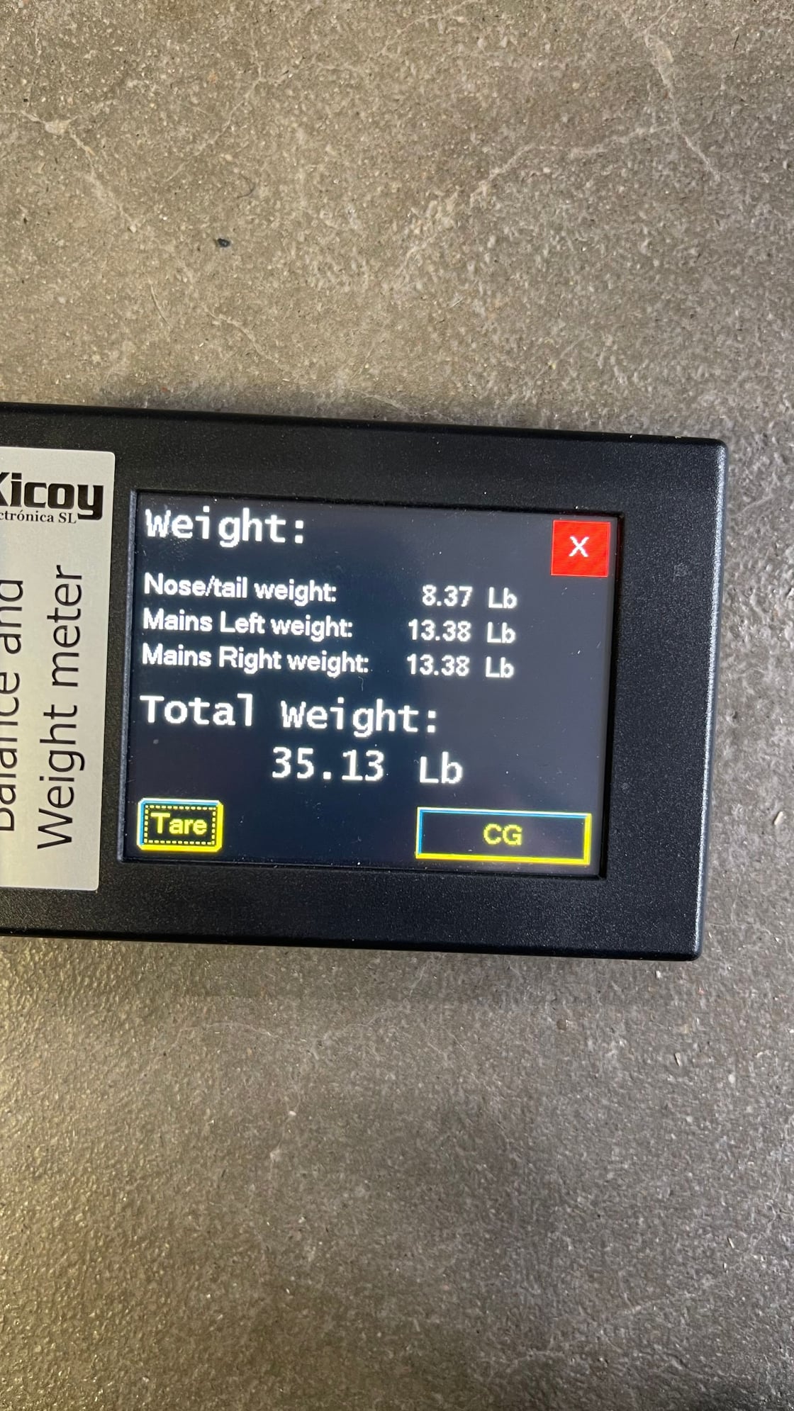
Weight came in lighter than Josh's but mostly due to the smaller turbine, interesting to note this is the 1st time I have seen left/right mains the same weight on any jet so thanks to Josh and his hard work taking the time to get balanced might be a fluke lol but all good, CG is nose heavy on mine but if I remember correctly at it was 0.4lbs nose heavy once the header tank is empty (same header tank as Gary's) ... Josh thinks it will be lighter on than nose than his but we will see here shortly and compare the 2XLs, but I think there will be very little difference in handing. Weight as shown is with gear down, UAT full, batteries installed etc..
And my XL is about ready and now sits in my not flown hangar of jets, just some radio programing left and when the cold weather passes this week it will be ready for its 1st flight.
Weight came in lighter than Josh's but mostly due to the smaller turbine, interesting to note this is the 1st time I have seen left/right mains the same weight on any jet so thanks to Josh and his hard work taking the time to get balanced
might be a fluke lol but all good, CG is nose heavy on mine but if I remember correctly at it was 0.4lbs nose heavy once the header tank is empty (same header tank as Gary's) ... Josh thinks it will be lighter on than nose than his but we will see here shortly and compare the 2XLs, but I think there will be very little difference in handing. Weight as shown is with gear down, UAT full, batteries installed etc.. 04-13-2021, 07:55 AM
#110

So per wikipedia there were only 2 built, but I've now seen 3 different schemes on full scale birds (these 2 above and the NASA 2 seater). Perhaps the multi-gray bottomed plane above was the 2 seater and was later given the NASA scheme.

 04-13-2021, 01:29 PM
#114
Interesting. So only two aircraft ever produced, but by my count so far 5 schemes between them. Looks like the 1-seater (AF 749, NASA 849) wore at least four schemes over the years. Cool history.
The following users liked this post:
Viper1GJ (04-13-2021)
The following users liked this post:
perttime (07-17-2021)
 04-13-2021, 04:41 PM
#117
Thread Starter
My Feedback: (20)
Hi Tom,
My understanding is the XL I have is a 1st production run from a new factory, Global Knight Models. It does have some issues for an ARF at this price point but I think they are taking notes and will make improvements on future production. I do not know where the GJC F-86 is made and it may be just fine.
I think this one will fly great but there are some improvements that are needed for sure.
Gary
Last edited by Viper1GJ; 04-13-2021 at 06:12 PM.
04-13-2021, 05:29 PM
#118
Thread Starter
My Feedback: (20)
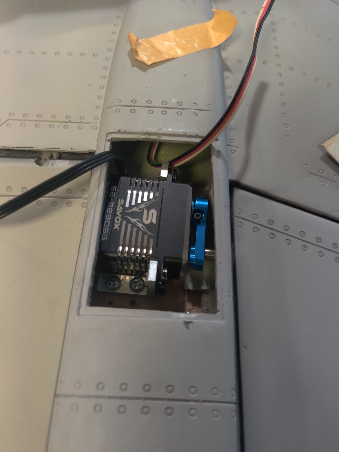
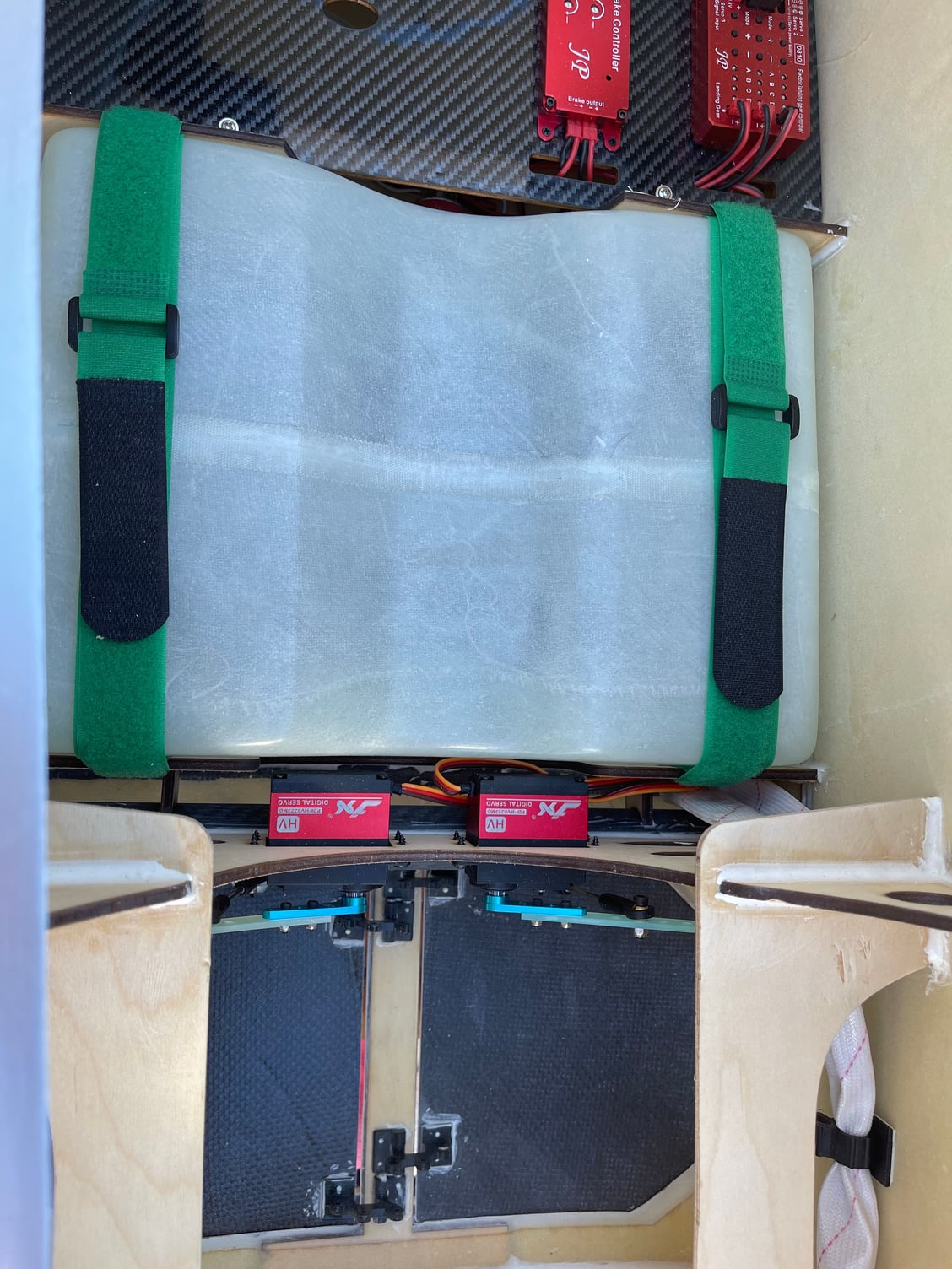
Aileron linkage issues
I was getting significant binding when ailerons were deflected past about 15 degrees.
Binding happened in both directions and put pressure on the missile rail hinge point. You could see the rail and trailing edge of the wing twisting.
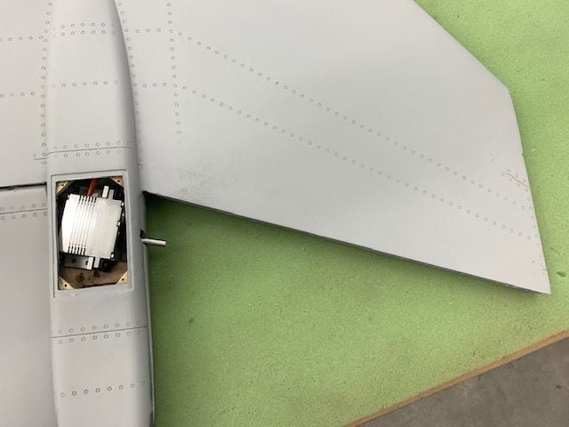
I discovered the reason was that because the hinge line is swept relative to the axis of the servo spline and pin. When the aileron moves, the root of the aileron changes angles and puts binding pressure on the pin in the slot. I tried rotating the servo to align as much as possible to the hinge line and it significantly reduced the binding and twisting of the missile rail so I remounted the aileron servos.
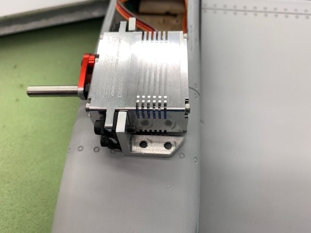
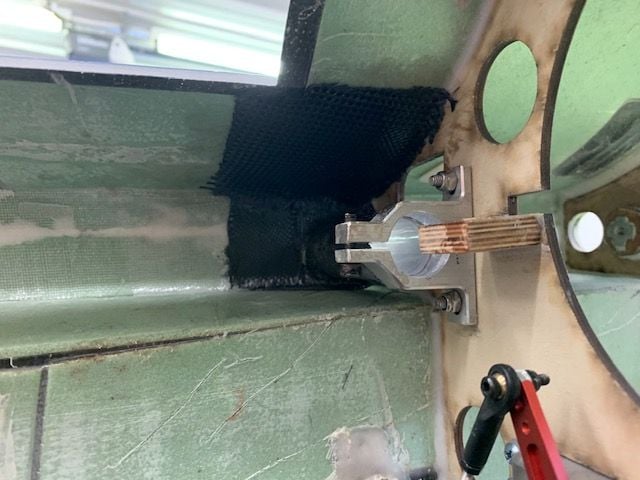
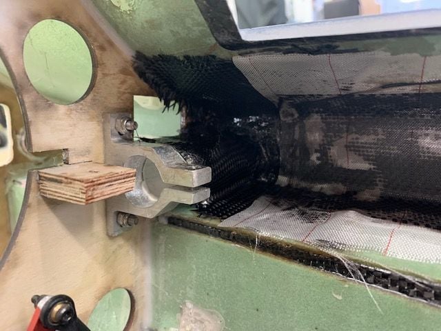
I trimmed the corner of the trailing servo mount lug
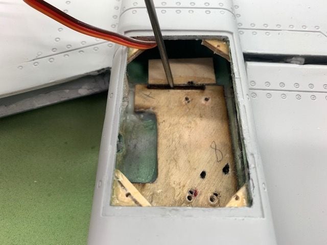
I added a block of wood ahead of the servo tray to catch the forward screw which wound up on the edge of the tray.
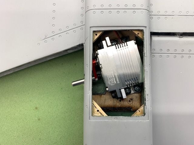
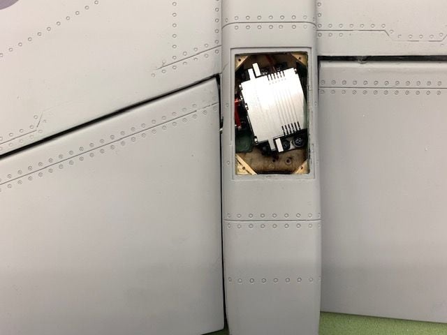
Servo remounted for testing
Now it works much better but I'm stilled not thrilled about the pin sliding in a plywood slot over time and developing slop.
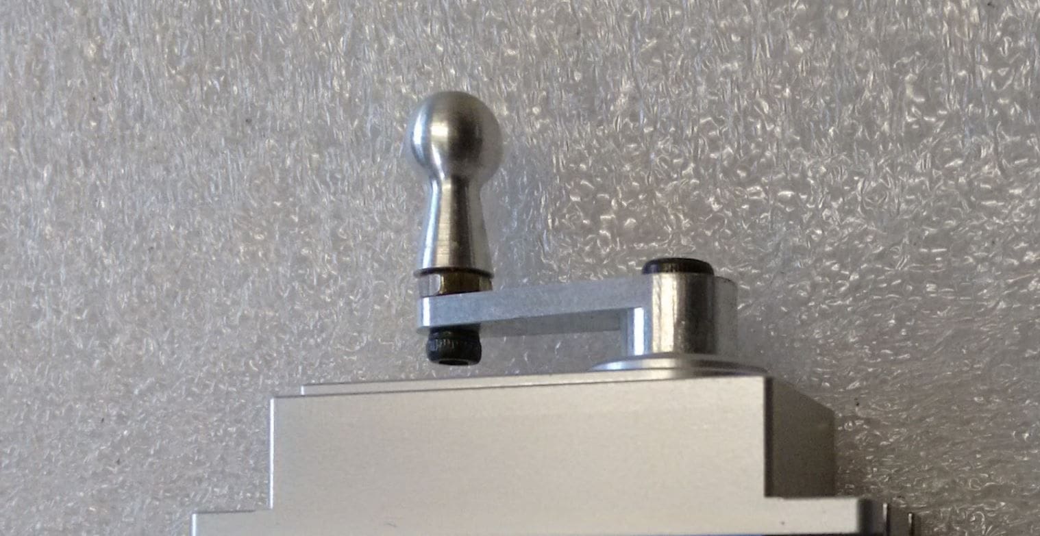
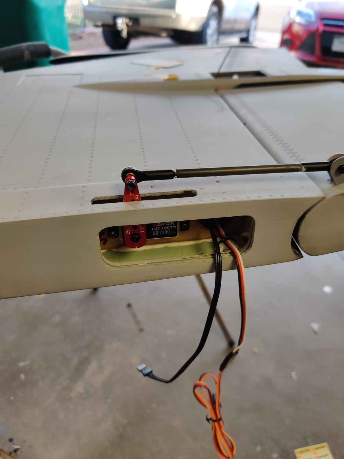
When using a direct servo drive into the root of the moving surface and the hinge line is not parallel to the servo spline and pin, I highly recommend using a ball stud drive similar to this. This solves the changing angle problem with the straight pin and results in a much smoother motion with no binding.
I also recommend the slot be machined metal or plastic so that the ball drive pin will not wear and develop slop over time.

The inboard elevator/elevon surface has a traditional pushrod setup and was installed with no issues. I had the proper size Pro Link turnbuckle on hand so it was easy to adjust.
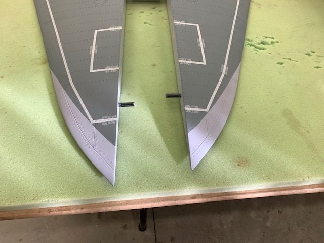
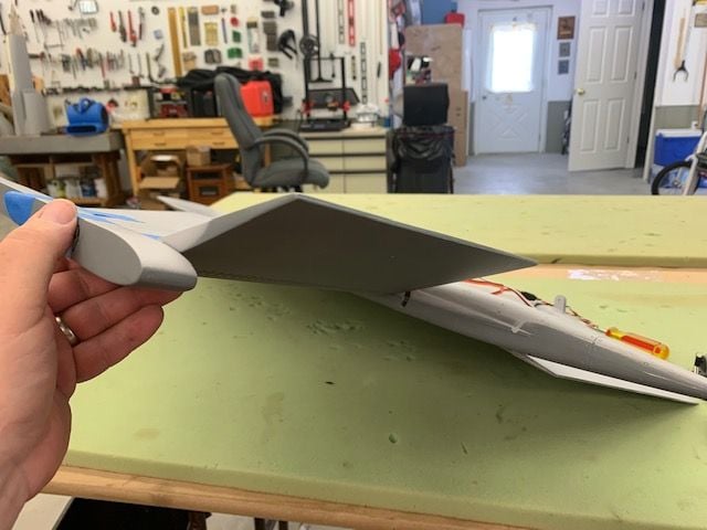
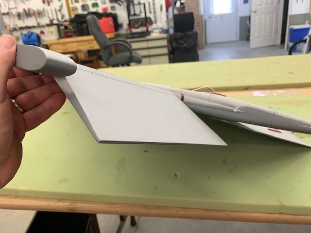
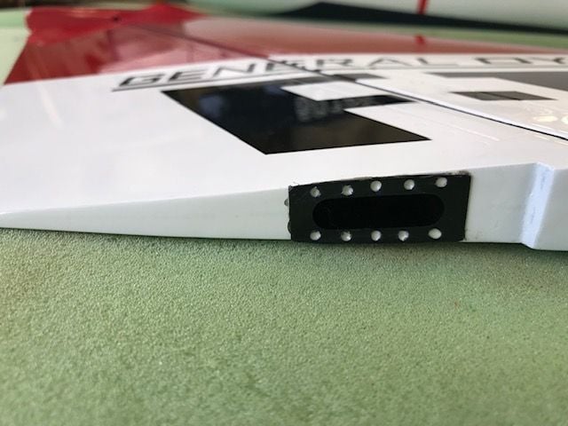
The wings were finished and missile rails installed. I noticed that both rails had a positive incidence angle which makes them look goofy. F-16 missile rails have a negative incidence angle. This will not be easy to fix since changing the angle of the rail effects the outside hinge point of the aileron and leaves the missile rail not centered on the wing tip. I'll just ignore it for now.
I had seen this before in photos of the prototype and other videos. I thought it was that the rail was just not adjusted correctly but it seems as if the factory installed missile rail bolts and blind nuts are set this way.
You can see the negative incident angle of the XL missile rails on both sides here.
Same here.
I was getting significant binding when ailerons were deflected past about 15 degrees.
Binding happened in both directions and put pressure on the missile rail hinge point. You could see the rail and trailing edge of the wing twisting.
I discovered the reason was that because the hinge line is swept relative to the axis of the servo spline and pin. When the aileron moves, the root of the aileron changes angles and puts binding pressure on the pin in the slot. I tried rotating the servo to align as much as possible to the hinge line and it significantly reduced the binding and twisting of the missile rail so I remounted the aileron servos.
I trimmed the corner of the trailing servo mount lug
I added a block of wood ahead of the servo tray to catch the forward screw which wound up on the edge of the tray.
Servo remounted for testing
Now it works much better but I'm stilled not thrilled about the pin sliding in a plywood slot over time and developing slop.
When using a direct servo drive into the root of the moving surface and the hinge line is not parallel to the servo spline and pin, I highly recommend using a ball stud drive similar to this. This solves the changing angle problem with the straight pin and results in a much smoother motion with no binding.
I also recommend the slot be machined metal or plastic so that the ball drive pin will not wear and develop slop over time.
The inboard elevator/elevon surface has a traditional pushrod setup and was installed with no issues. I had the proper size Pro Link turnbuckle on hand so it was easy to adjust.
The wings were finished and missile rails installed. I noticed that both rails had a positive incidence angle which makes them look goofy. F-16 missile rails have a negative incidence angle. This will not be easy to fix since changing the angle of the rail effects the outside hinge point of the aileron and leaves the missile rail not centered on the wing tip. I'll just ignore it for now.
I had seen this before in photos of the prototype and other videos. I thought it was that the rail was just not adjusted correctly but it seems as if the factory installed missile rail bolts and blind nuts are set this way.
You can see the negative incident angle of the XL missile rails on both sides here.
Same here.
Last edited by Viper1GJ; 04-13-2021 at 06:16 PM.
04-13-2021, 05:57 PM
#119
Thread Starter
My Feedback: (20)
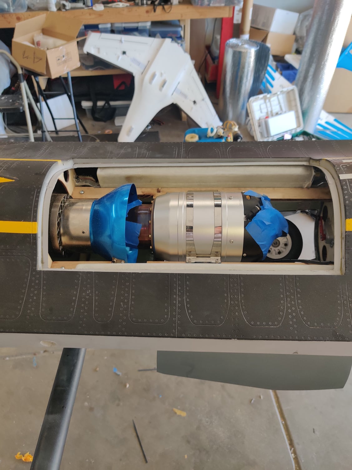
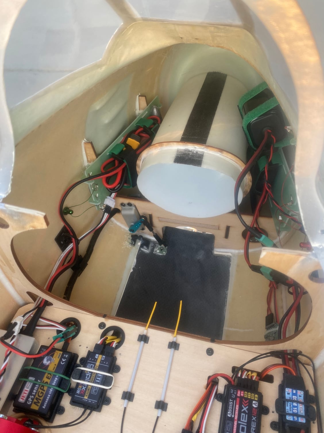
Mounting pipe and turbine
The factory pipe trailing edge position was planned to be about 2" inside the nozzle. I moved the pipe back flush with the trailing edge of the nozzle to shift weight aft based on recommendations Josh gave me.
The pipe and bell were moved aft about 33mm. The bell has to be removed from the pipe to get it in the fuse. I slid the pipe in from the rear and marked the position of the leading edge of the pipe and the new bell cutouts. New cutouts on the mounting rails were made and be bell reassembled.
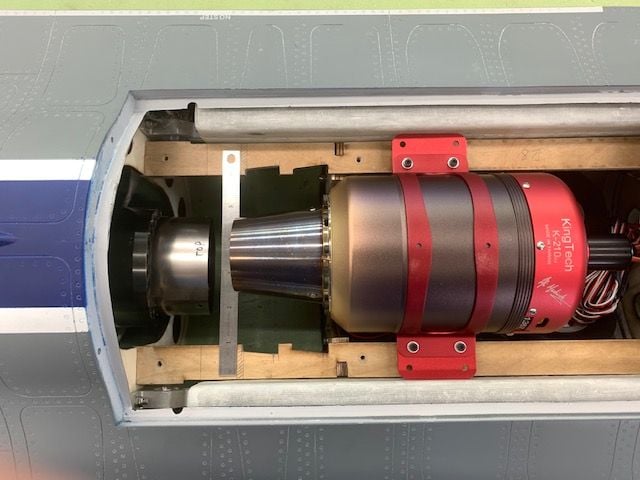
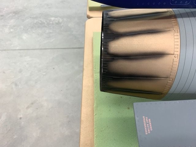
Trailing edge of the turbine nozzle is set 25mm ahead of the pipe and mounting positions marked
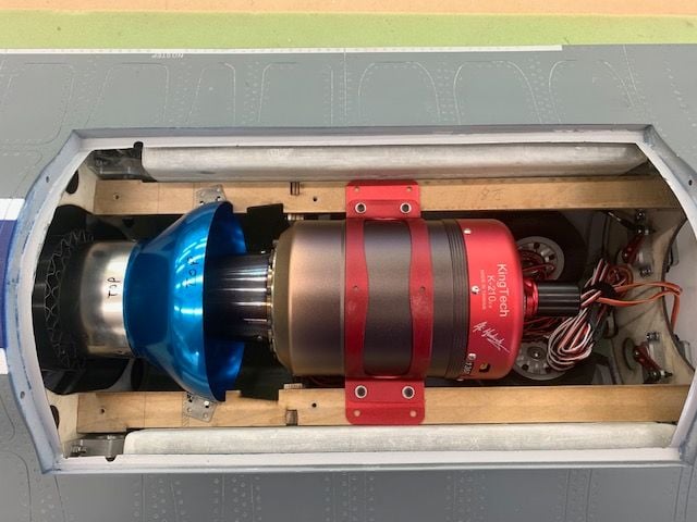
Relief cuts for the turbine bracket screws were made in the rails and the turbine set in place for dry fit.
At first look the turbine seems to be pretty close to center on the pipe. Not bad....
But the pipe is not centered in the nozzle. I'm not sure why. I've never seen an F-16 pipe that was not centered. I will have to investigate this one.
The factory pipe trailing edge position was planned to be about 2" inside the nozzle. I moved the pipe back flush with the trailing edge of the nozzle to shift weight aft based on recommendations Josh gave me.
The pipe and bell were moved aft about 33mm. The bell has to be removed from the pipe to get it in the fuse. I slid the pipe in from the rear and marked the position of the leading edge of the pipe and the new bell cutouts. New cutouts on the mounting rails were made and be bell reassembled.
Trailing edge of the turbine nozzle is set 25mm ahead of the pipe and mounting positions marked
Relief cuts for the turbine bracket screws were made in the rails and the turbine set in place for dry fit.
At first look the turbine seems to be pretty close to center on the pipe. Not bad....
But the pipe is not centered in the nozzle. I'm not sure why. I've never seen an F-16 pipe that was not centered. I will have to investigate this one.
04-13-2021, 06:05 PM
#120
Thread Starter
My Feedback: (20)
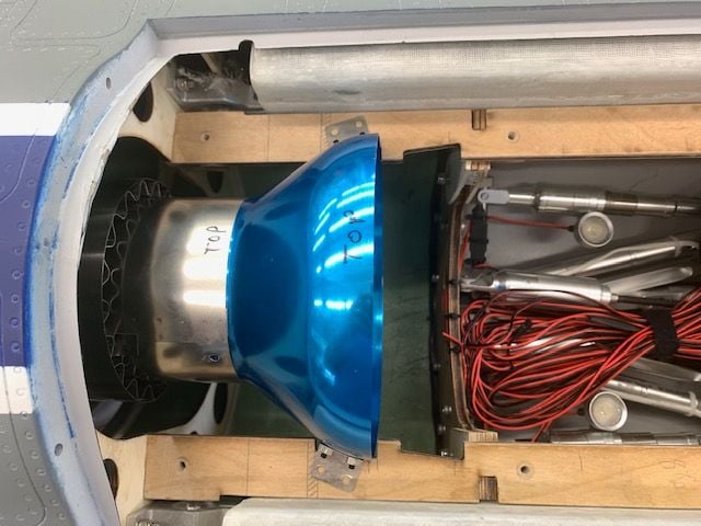
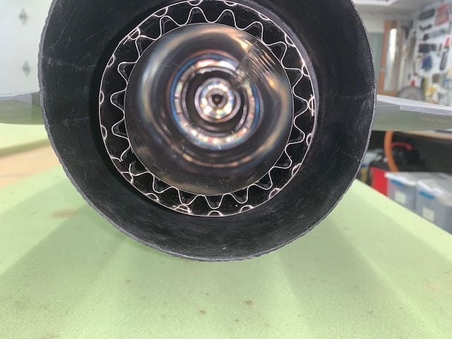
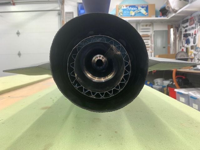
I need help with the LED afterburner ring.
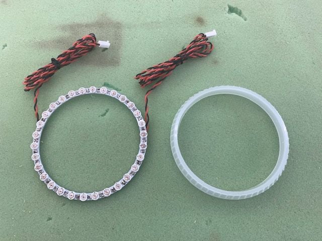
I have a nice Unilight LED AB ring and diffuser cover. I have not ever used one like this before. There are no mounting tabs or holes. Can anyone give me some advice on how to mount this ring and the diffuser cover?
The next question is the wiring. The long connector wires are soldered to the back of the LED ring. If the ring is mounted inside the nozzle someway, it seems that there is no way to unplug the AB ring to remove the nozzle. The wires would go forward well past the turbine bay where he plugs are. What do you guys who use these things do?
Advice requested!
Thanks,
Gary
04-13-2021, 06:29 PM
#121
My Feedback: (2)
Tp77fo -
My understanding is the F-86 is made by another factory. I saw and inspected it at Florida Jets and it was by far better quality, but as Gary mentioned these XL are 1st run, assuming Mike makes sure the improvements are made you should not have to do anything.
Regarding your F-86 decision and I do not speak for anyone at Global, but I have bought quite a few turbines and jets from them all I can say is if your unhappy with the quality or it does not meet your expectations, Ralph and I'm sure Mike will work with you to make sure your happy.
My experience so far has been that and same with this XL, it had issues similar to Gary's and inspection damage from customs (no fault of Global's) I could of returned it and got a full refund or a replacement without an issue, but rather put more unnecessary costs on expensive shipping back and fourth on Global I decided to work with them since they have always been fair and reasonable to deal with, anyone who knows me I don't paying fair value regardless of the cost, but I do expect as near as perfection as possible.
Untidy, poor built jets are not in my interests and the bonus you get with me is I am not easy to deal with lol, especially with when I know I'm getting the runaround from some RC companies that are not been upfront or transparent, but like I said that has not been my experience with Global so far and because of that they will earn more business from me, especially if they listen to improve their QC. I like my BVM jets just as much as you do I have another jet ordered (F-1), but so far I like what Mike, Carrie and Ralph have done at Global so I'll let leave it at that. Remember I'm just a customer and nothing more.
My understanding is the F-86 is made by another factory. I saw and inspected it at Florida Jets and it was by far better quality, but as Gary mentioned these XL are 1st run, assuming Mike makes sure the improvements are made you should not have to do anything.
Regarding your F-86 decision and I do not speak for anyone at Global, but I have bought quite a few turbines and jets from them all I can say is if your unhappy with the quality or it does not meet your expectations, Ralph and I'm sure Mike will work with you to make sure your happy.
My experience so far has been that and same with this XL, it had issues similar to Gary's and inspection damage from customs (no fault of Global's) I could of returned it and got a full refund or a replacement without an issue, but rather put more unnecessary costs on expensive shipping back and fourth on Global I decided to work with them since they have always been fair and reasonable to deal with, anyone who knows me I don't paying fair value regardless of the cost, but I do expect as near as perfection as possible.
Untidy, poor built jets are not in my interests and the bonus you get with me is I am not easy to deal with lol, especially with when I know I'm getting the runaround from some RC companies that are not been upfront or transparent, but like I said that has not been my experience with Global so far and because of that they will earn more business from me, especially if they listen to improve their QC. I like my BVM jets just as much as you do
I have another jet ordered (F-1), but so far I like what Mike, Carrie and Ralph have done at Global so I'll let leave it at that. Remember I'm just a customer and nothing more.Last edited by F900; 04-13-2021 at 06:35 PM.
04-13-2021, 06:50 PM
#122

My Feedback: (67)
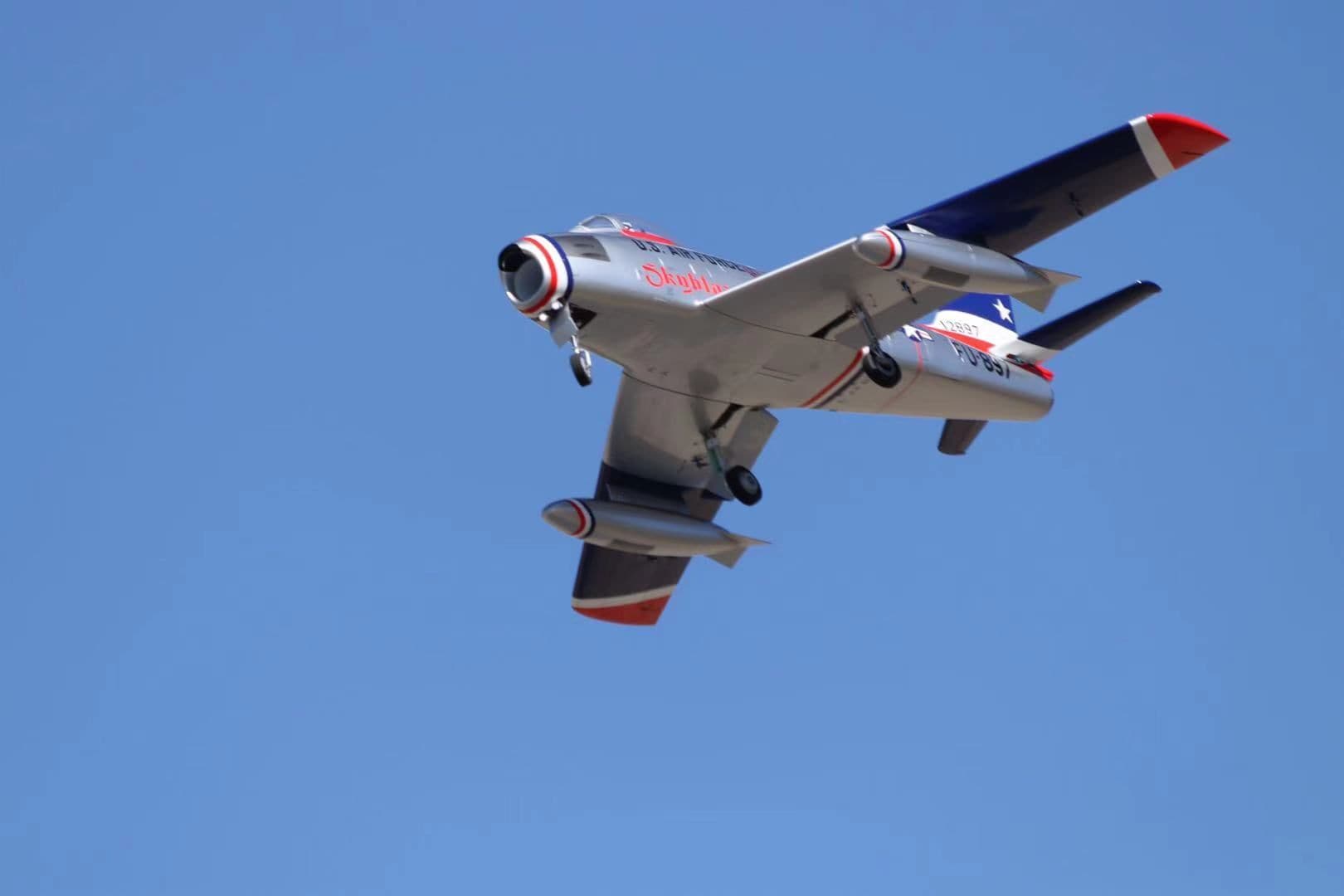
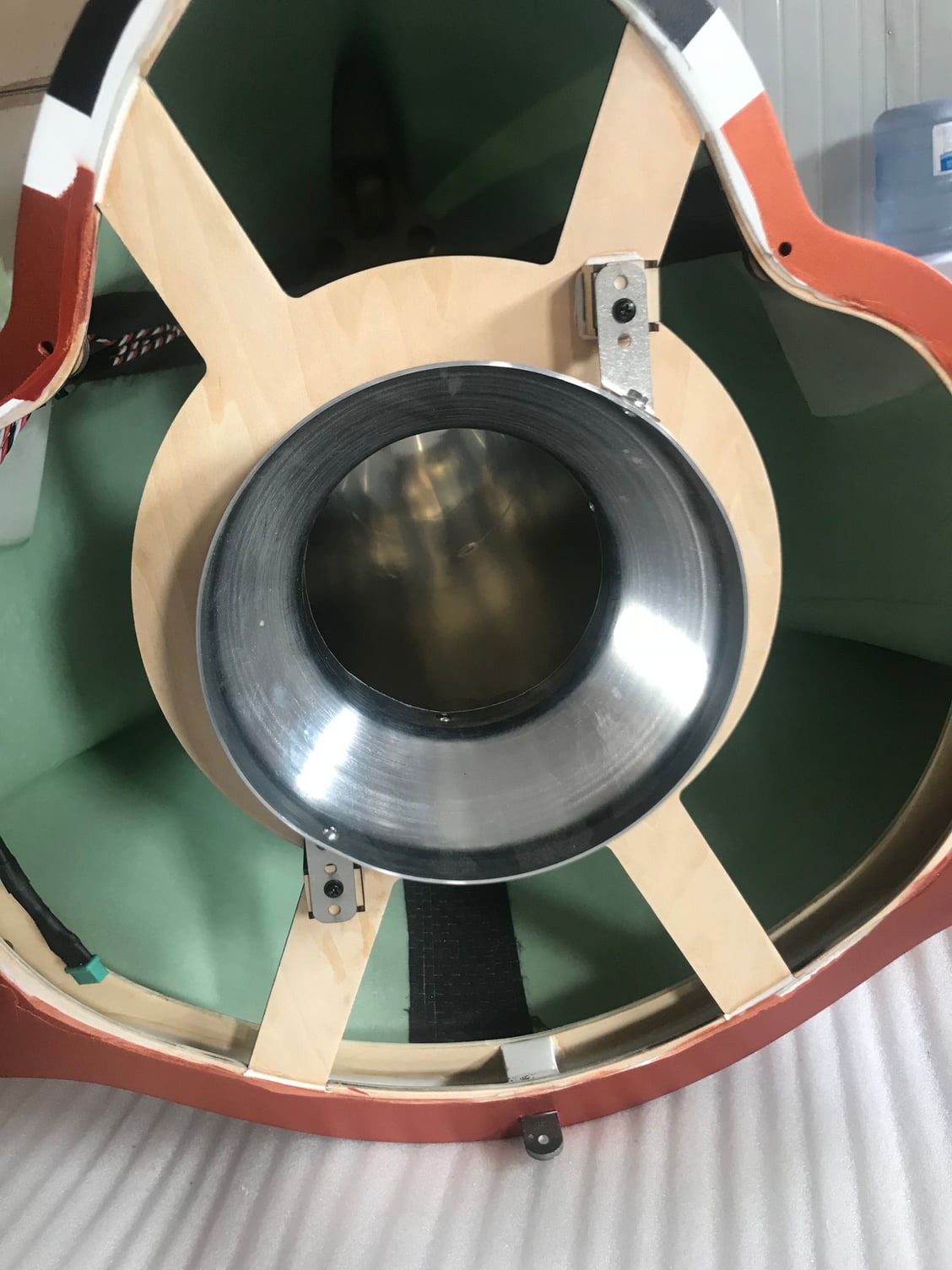
Here are some photos of the interior of the Sabre. You can see the difference in quality and finish.
Based on my 50+ flights I have seen problems
1. Nose gear not coming down - caused by flimsy strut Fork - It's resolved wth beefier fork -
2. main gear plates - too weak and would crack over time - resolved with different screws and thicker wooden blocks and carbon fiber.
One thing I really like about this Sabre is that the doors closed tight and smooth. Looks really neat from the bottom. I would try to start up a thread for that when I get my customized one "Mike's Bird" next month. This series of jets are focusing on "Turn Key", all Electric L/G/doors/brake, Reliable, 80% scale/20%sport (less panel lines and scale details) The targeted customers are different - It's more for reliability, easy to fly, easy to maintain, but create look scale composite jets that's reasonably priced.
Mike


The following users liked this post:
Viper1GJ (04-14-2021)