


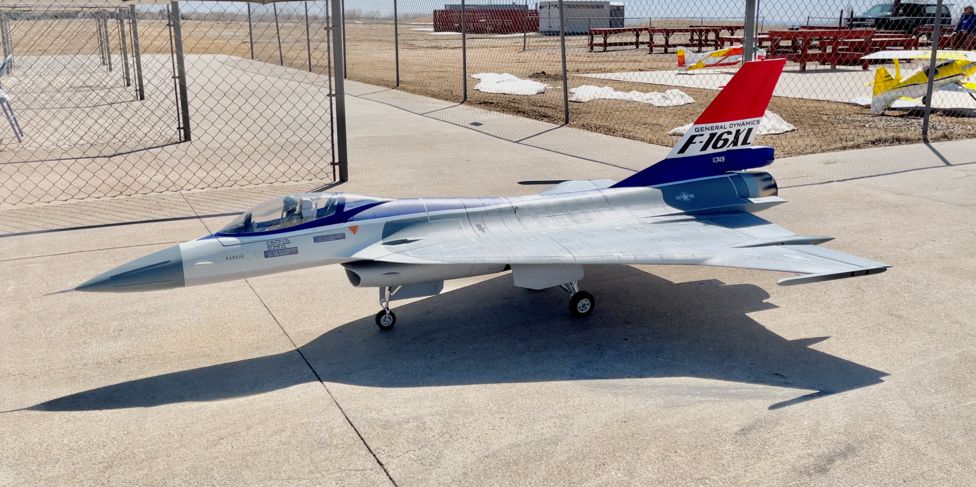
F-16XL ARF by Global Knight Models from Global Jet Club


 03-31-2021, 02:36 PM
#77

Thread Starter
My Feedback: (20)
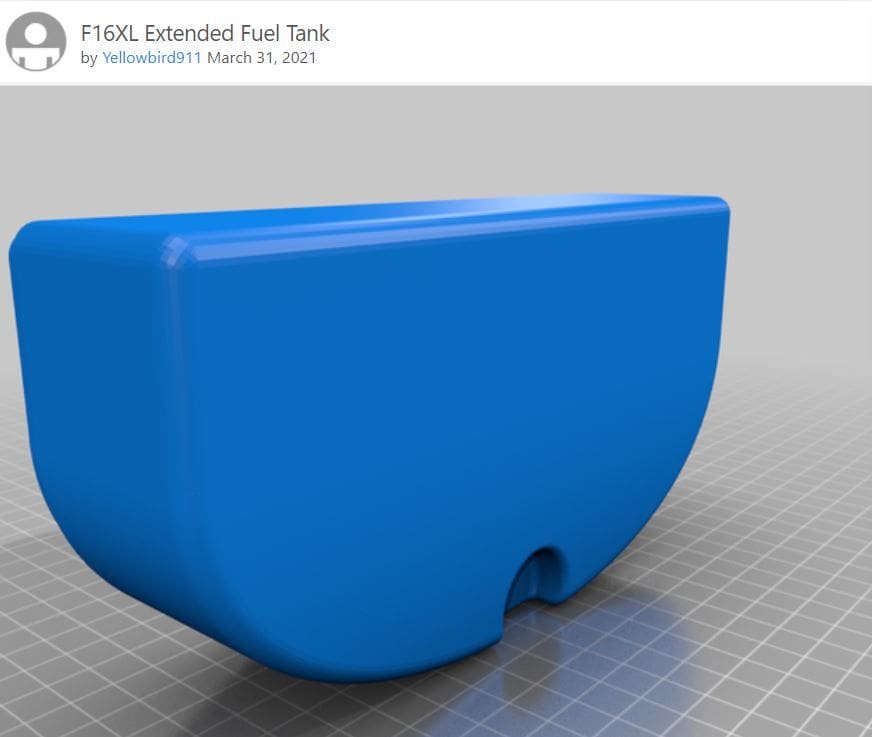
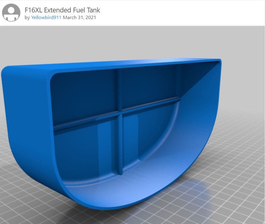
Here are the CAD .stl files for the aux fuel tank.
It is listed in Thingiverse as: F16XL Extended Fuel Tank
https://www.thingiverse.com/thing:4812599
It is listed in Thingiverse as: F16XL Extended Fuel Tank
https://www.thingiverse.com/thing:4812599
03-31-2021, 03:44 PM
#78
Thread Starter
My Feedback: (20)
Install aileron servos
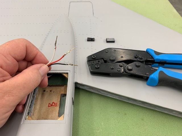
First was installing a servo plug on the pre installed extension wire. Male pins crimped on wires.
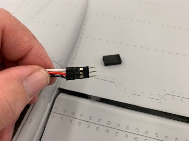
Connector housing over pins
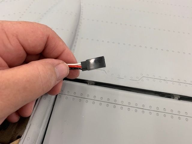
Connector sleeve over pin housing
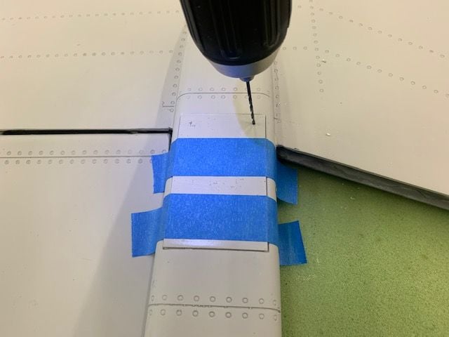
Screw holes drilled in hatch cover
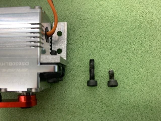
Had to fuss with servo mounting bolts. The supplied bolts were hand cut to about 6mm and would not engage 3mm threads in servo L bracket. If you did not use the grommets and eyelets the bolt heads fell right through the holes in the servo mounting tabs. I used the grommets and eyelets to keep the bolts centered in the servo mount holes so I used 12 mm bolts. However the lower 12mm bolts interfered with the inside wood screw. So I cut them down to 8mm and all was well.
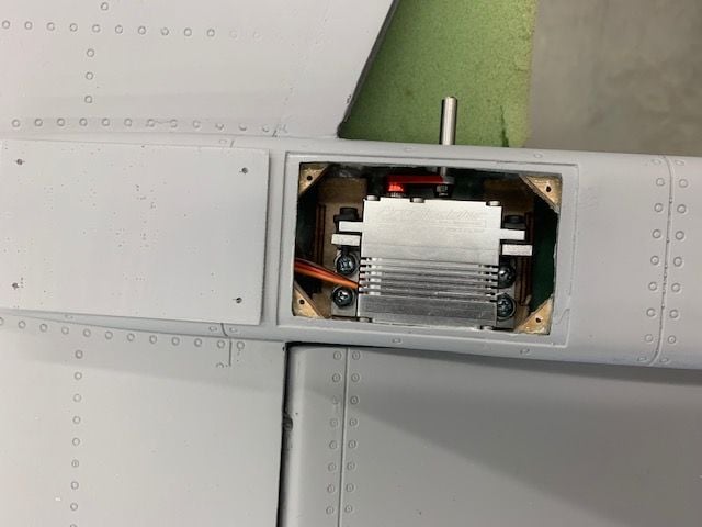
Servos mounted using the 6-32 nuts as spacers to keep the screws from punching through the upper wing skin.
Hatch cover installed. It is all flat so it does not fit the contour of the faring very well.
Other side is the side the same.
Hatch needs to be molded to fit he curves on the sides.
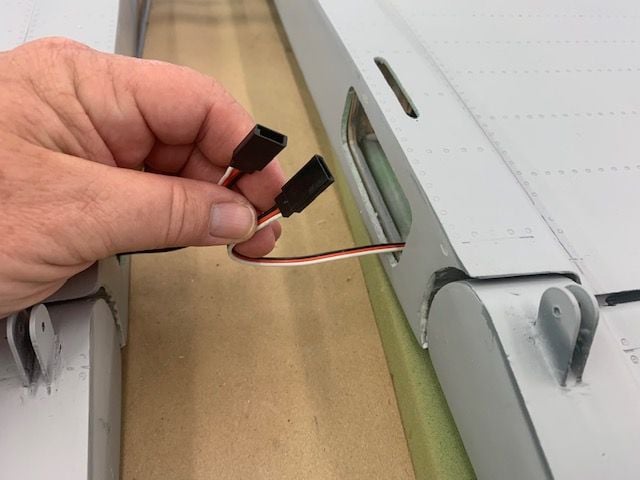
I got ready to install a servo tester to check the servo throws and discovered there was a female housing on the extension at the wing root. It is set up so that the elevator and aileron can not be cross connected but it was unexpected. Had to use a male to male extension to connect servo tester. This would complicate use of the multi plug connector I was thinking about using. I'll just stick to the preinstalled plugs.
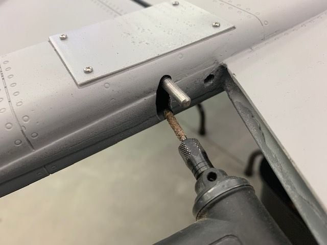
I had to slightly grind a little clearance for the drive pin on both sides.
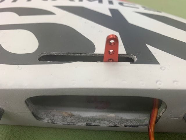
Rudder horn slot a little offset to the rear but not bad.
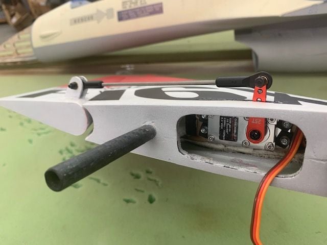
Rudder linkage was standard and no issue. I will either sleeve the threaded rod or replace with a pro link type rod.
First was installing a servo plug on the pre installed extension wire. Male pins crimped on wires.
Connector housing over pins
Connector sleeve over pin housing
Screw holes drilled in hatch cover
Had to fuss with servo mounting bolts. The supplied bolts were hand cut to about 6mm and would not engage 3mm threads in servo L bracket. If you did not use the grommets and eyelets the bolt heads fell right through the holes in the servo mounting tabs. I used the grommets and eyelets to keep the bolts centered in the servo mount holes so I used 12 mm bolts. However the lower 12mm bolts interfered with the inside wood screw. So I cut them down to 8mm and all was well.
Servos mounted using the 6-32 nuts as spacers to keep the screws from punching through the upper wing skin.
Hatch cover installed. It is all flat so it does not fit the contour of the faring very well.
Other side is the side the same.
Hatch needs to be molded to fit he curves on the sides.
I got ready to install a servo tester to check the servo throws and discovered there was a female housing on the extension at the wing root. It is set up so that the elevator and aileron can not be cross connected but it was unexpected. Had to use a male to male extension to connect servo tester. This would complicate use of the multi plug connector I was thinking about using. I'll just stick to the preinstalled plugs.
I had to slightly grind a little clearance for the drive pin on both sides.
Rudder horn slot a little offset to the rear but not bad.
Rudder linkage was standard and no issue. I will either sleeve the threaded rod or replace with a pro link type rod.
03-31-2021, 03:48 PM
#79
Thread Starter
My Feedback: (20)
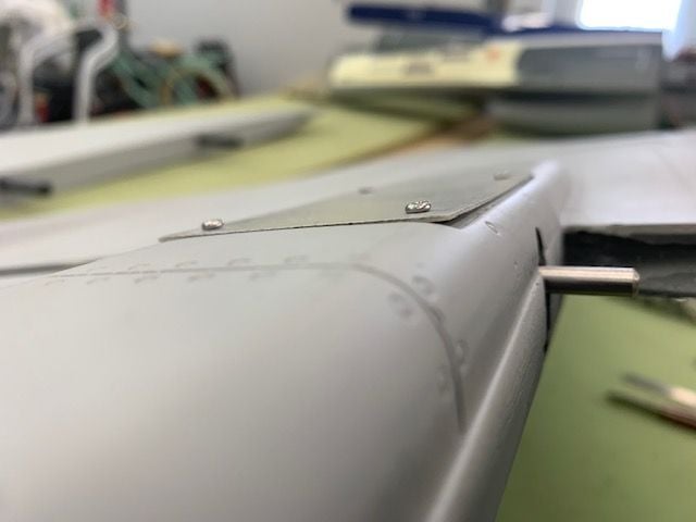
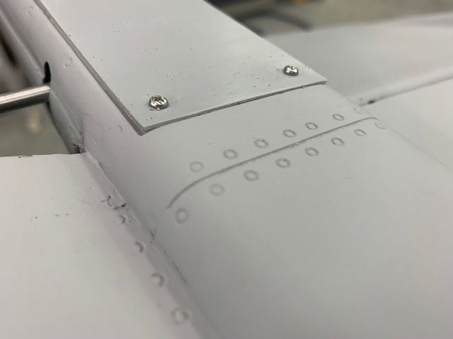
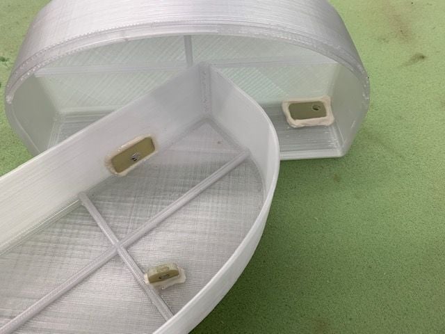
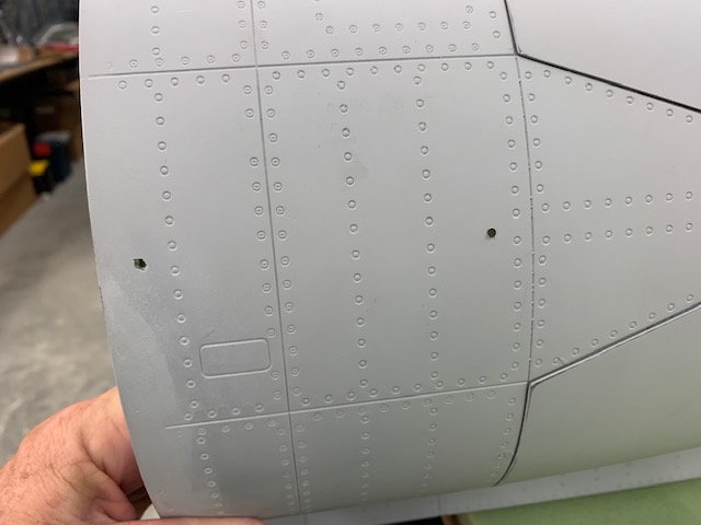
Mystery flat spots
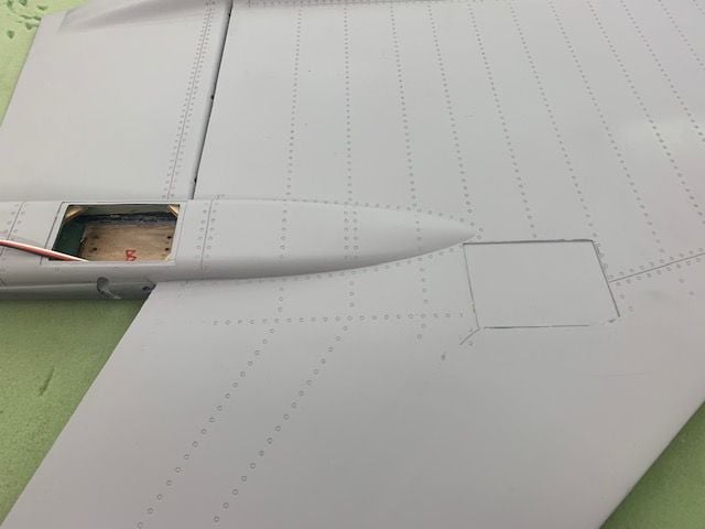
Flat area on bottom of both wings. Looks like it could have been a servo hatch cut out that was not used.
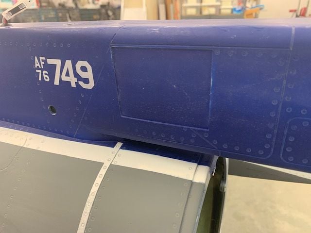
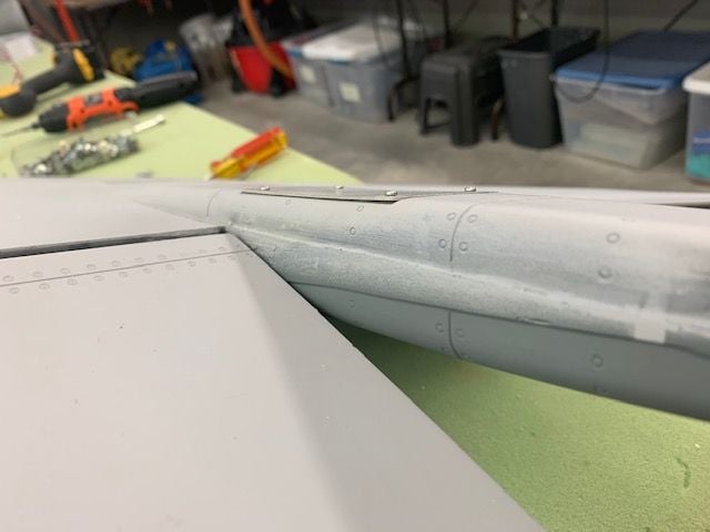
Same recessed flat spot on lower dorsal. I figured a future drag chute system may hide in here.
Flat area on bottom of both wings. Looks like it could have been a servo hatch cut out that was not used.
Same recessed flat spot on lower dorsal. I figured a future drag chute system may hide in here.
 04-01-2021, 11:38 AM
#81
Thread Starter
My Feedback: (20)
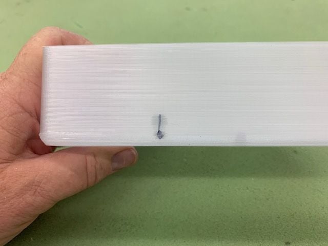
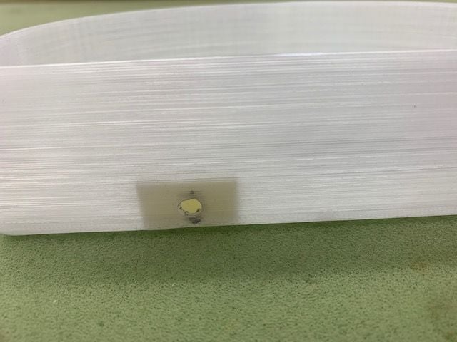
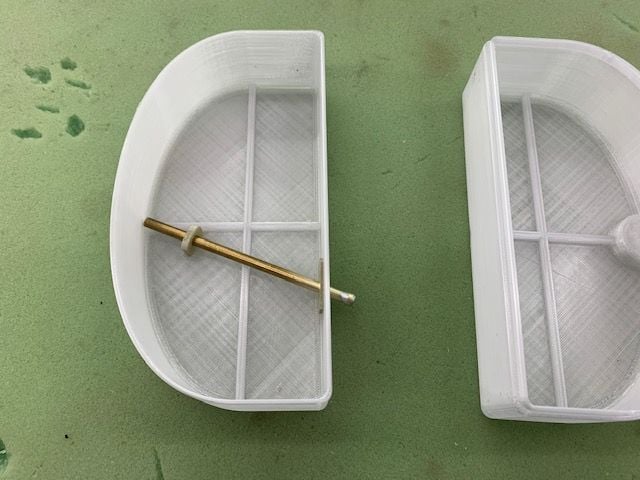
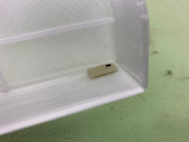
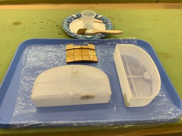
Fabricating tank plumbing. PIcs are pretty much self explaining
Marking loation of feed tube. Pickup is in center rear of tank. Output goes vent on left saddle tank through the round hole.
Marked back edge of tank
Marked top view
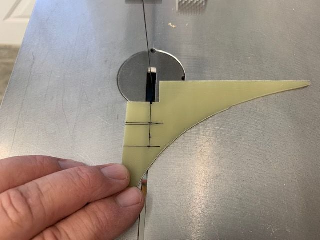
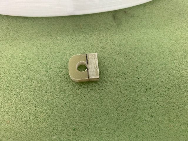
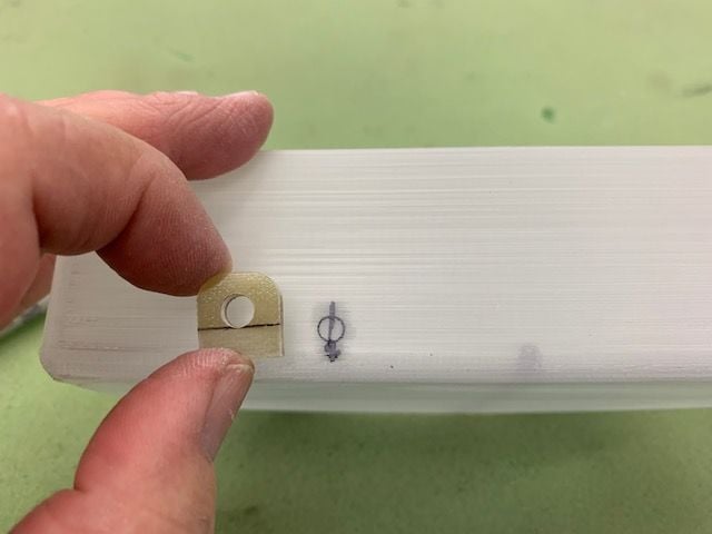
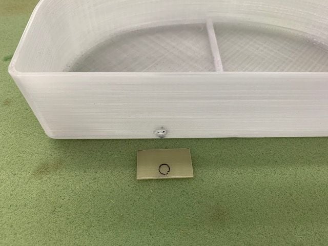
Scrap 1/16" G10 used for tank fixtures. 15 x 15mm squares used for pick up tube stand off
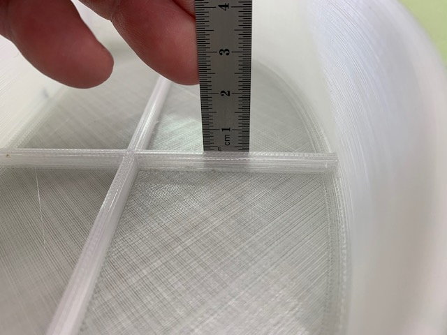
Tube has to clear 5mm rib on back of tank
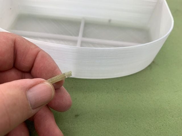
Two squares of G10 glued together with medium CA
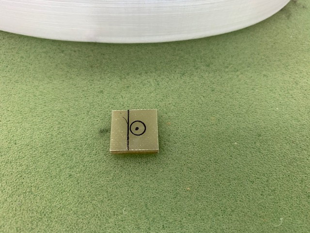
The plot!
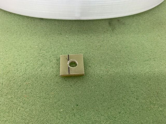
Hole drilled for tube
All gluing surfaces are scuff sanded inside and outside the tank
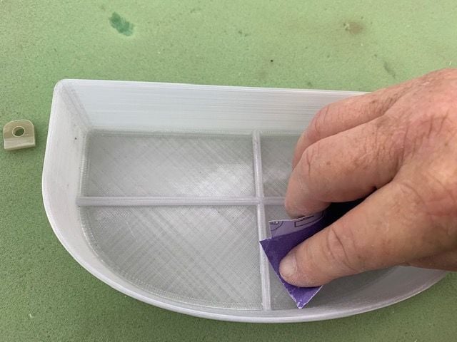
Scuff sanding back wall for standoff
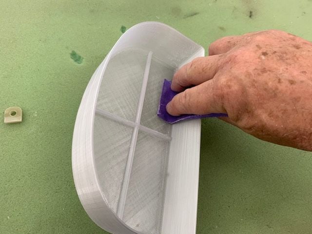
Scuff sanding inside of tank. Outside done too
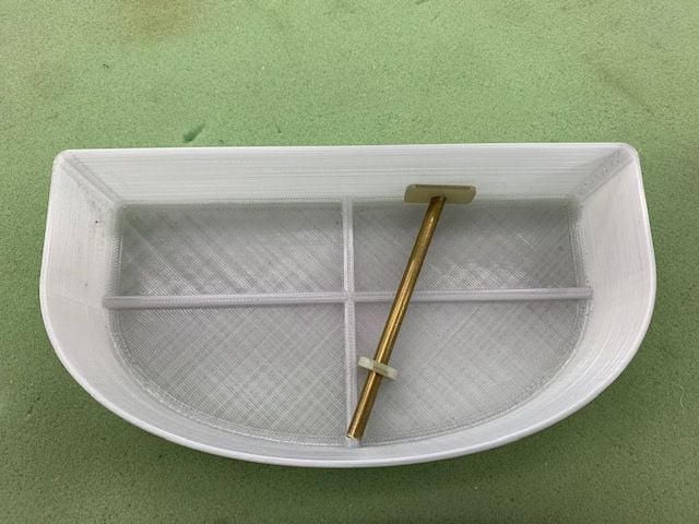
Top hole location marked away from back edge
Hole set for 5mm off the inside back wall
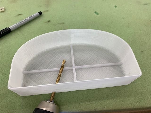
Drilled
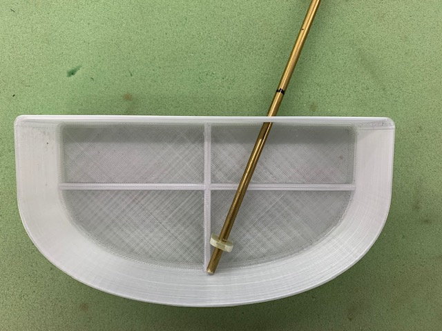
Tubing dry fit and marked for cut.
Marking loation of feed tube. Pickup is in center rear of tank. Output goes vent on left saddle tank through the round hole.
Marked back edge of tank
Marked top view
Scrap 1/16" G10 used for tank fixtures. 15 x 15mm squares used for pick up tube stand off
Tube has to clear 5mm rib on back of tank
Two squares of G10 glued together with medium CA
The plot!
Hole drilled for tube
All gluing surfaces are scuff sanded inside and outside the tank
Scuff sanding back wall for standoff
Scuff sanding inside of tank. Outside done too
Top hole location marked away from back edge
Hole set for 5mm off the inside back wall
Drilled
Tubing dry fit and marked for cut.
04-01-2021, 11:48 AM
#82
Thread Starter
My Feedback: (20)
Tank continued...
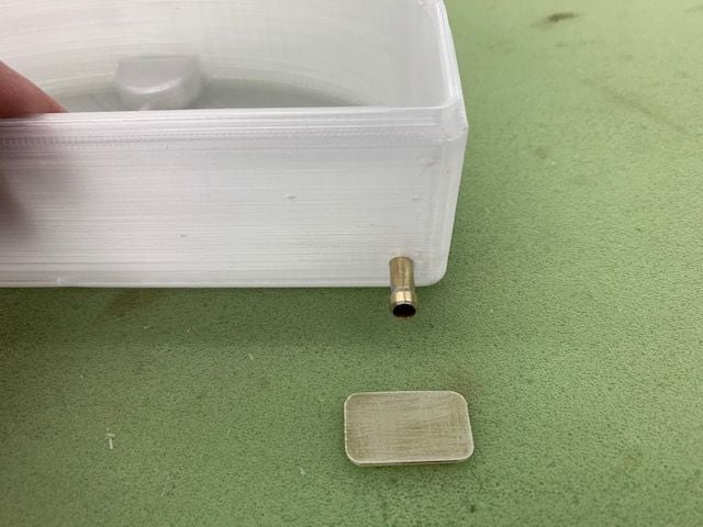
15 x 25mm G10 strain relief for top exit
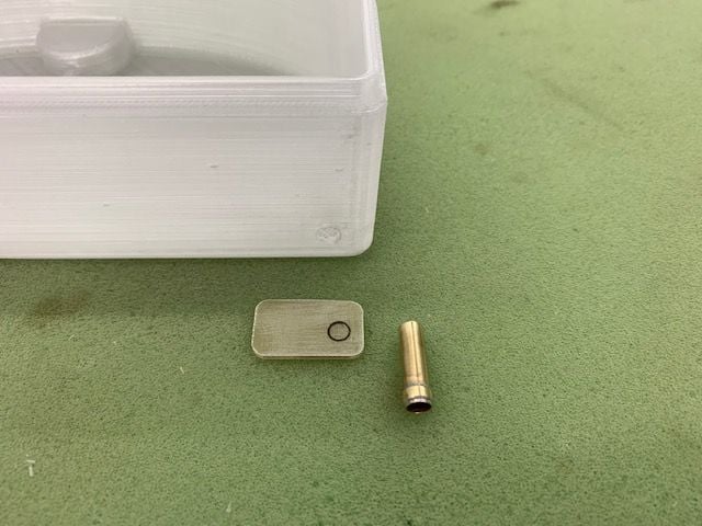
Hole marked
Hole drilled and dry fit
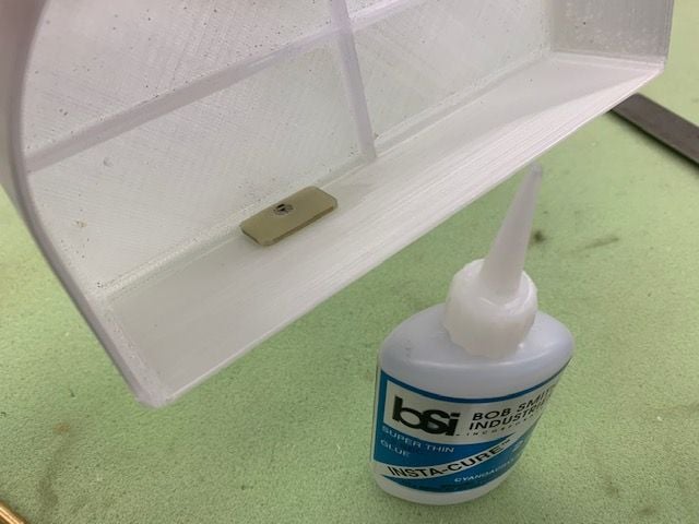
Strain relief glued in with thin CA
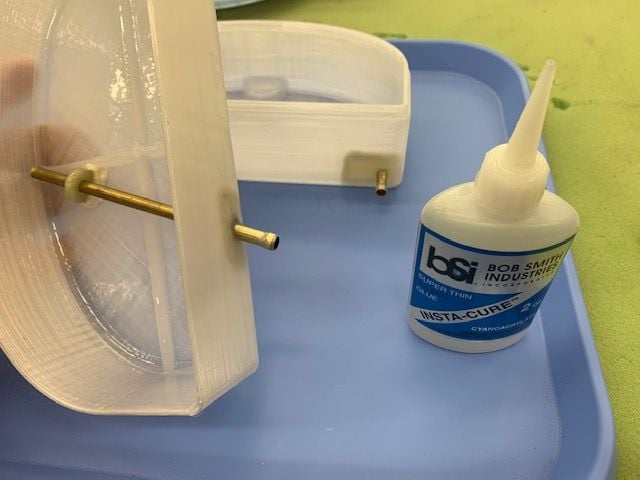
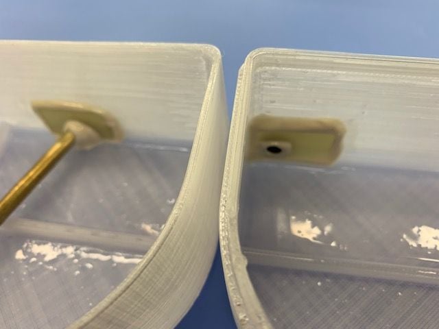
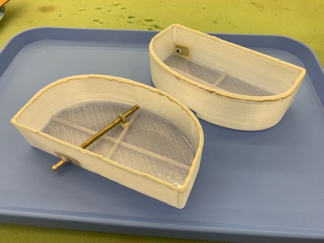
Location of lower stand off dry fit
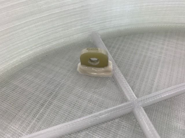
Lower stand off glued in with thin CA. No glue in stand off hole. This is a slip fit and allows the tube to move in the stand off during expansion and contraction.
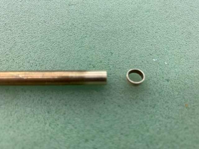
Homemade tubing barb ready for solder
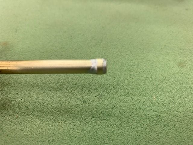
Finished barb
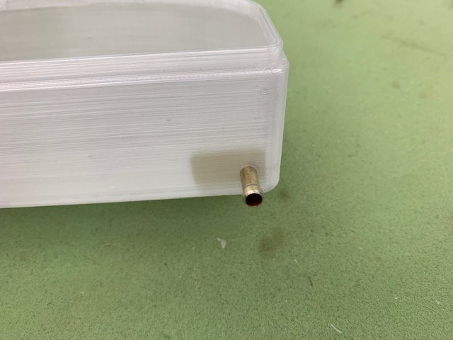
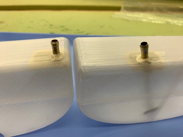
Final fit
Tank vent prepared the same way
Hole marked
Drilled
Strain relief glued in with thin CA
The final look
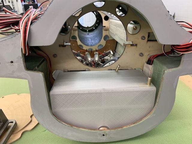
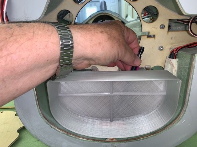
Test fit in jet
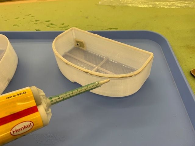
Parts glued in with Hysol
Care taken not to get glue inside the holes
15 x 25mm G10 strain relief for top exit
Hole marked
Hole drilled and dry fit
Strain relief glued in with thin CA
Location of lower stand off dry fit
Lower stand off glued in with thin CA. No glue in stand off hole. This is a slip fit and allows the tube to move in the stand off during expansion and contraction.
Homemade tubing barb ready for solder
Finished barb
Final fit
Tank vent prepared the same way
Hole marked
Drilled
Strain relief glued in with thin CA
The final look
Test fit in jet
Parts glued in with Hysol
Care taken not to get glue inside the holes
Last edited by Viper1GJ; 04-01-2021 at 12:25 PM.
04-01-2021, 12:39 PM
#83
Thread Starter
My Feedback: (20)
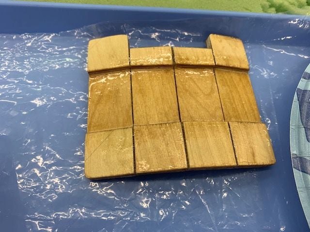
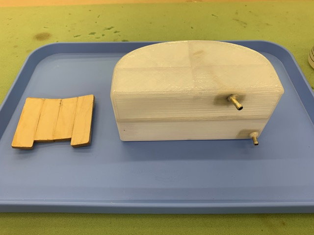
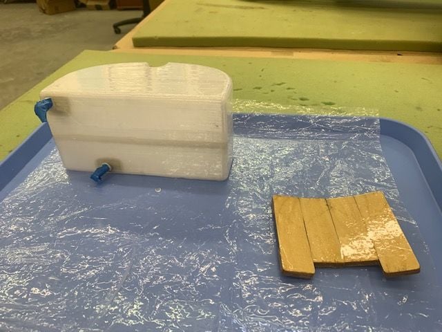
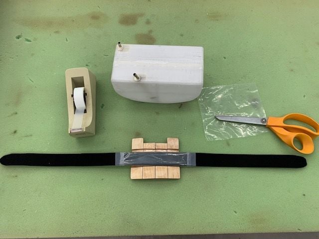
Plywood tank mount
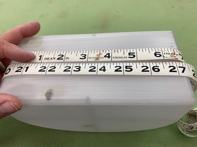
Measured 25" around tank with overlap
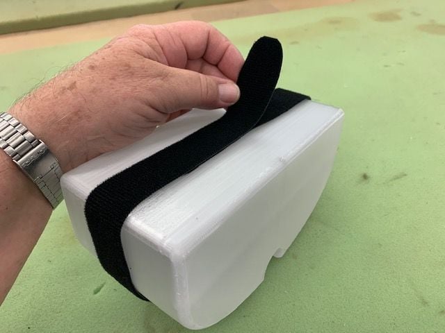
Strip of 1" Velcro One Wrap will hold tank to mount. Both ends cut rounded to slide under the mount.
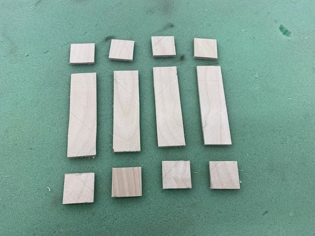
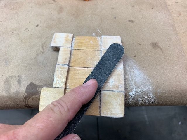
1/8" plywood parts four 1" x 3.5" and eight 1" x 1"
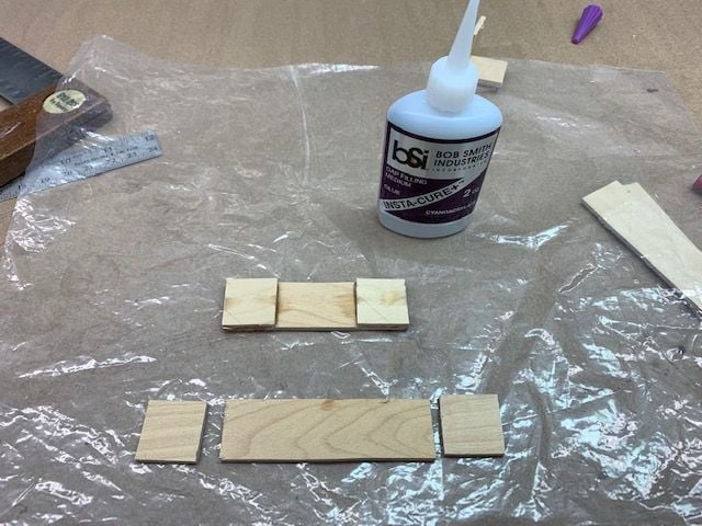
Parts glued together with medium CA
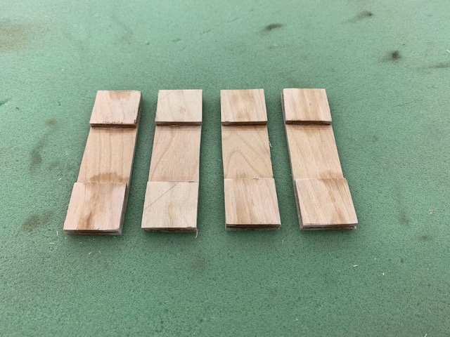
All done
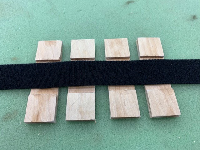
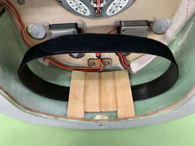
Strap will fit in recessed area under mounts
Clear packing tape applied to bottom of tank and center line marked
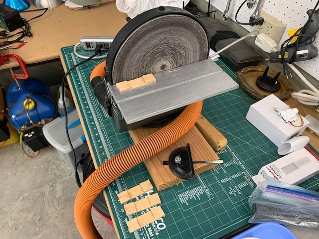
Mount edges straighten on disc sander
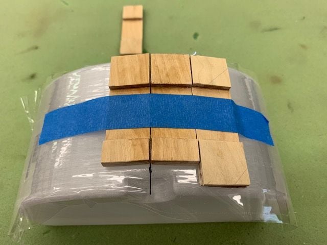
Mounts tacked glued together with medium CA and kicker
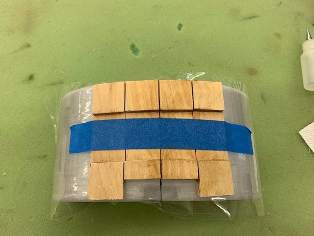
Tape removed and all joints glued again.
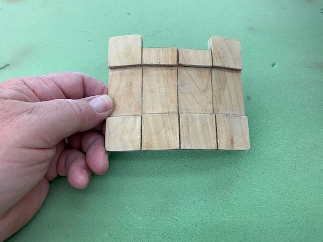
After a little clean up sanding
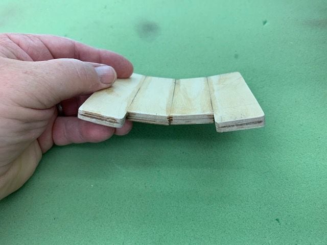
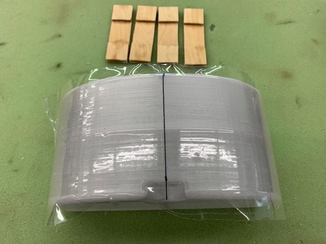
Front view. I wish I had only cut out half of the center sections but got in a hurry and cut them both off.
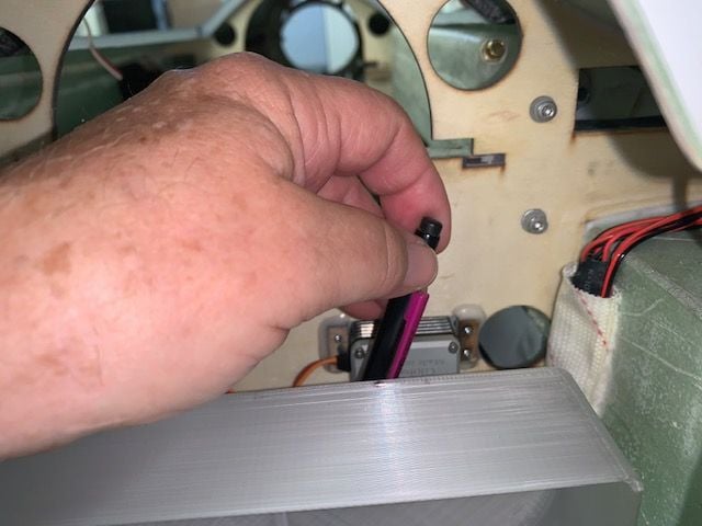
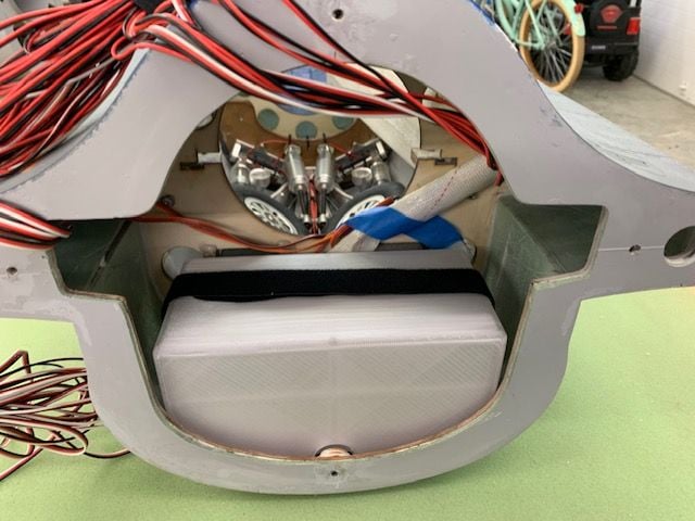
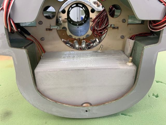
Dry fit in fuse. Mount will be epoxied into bottom of fuse with Six10 epoxy
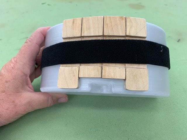
Bottom of tank dry fit of strap
Test fit on mount in jet. Seems to fit pretty good. I actually did these steps before I drilled the holes in the tank but I got the pics out of sequence.
Measured 25" around tank with overlap
Strip of 1" Velcro One Wrap will hold tank to mount. Both ends cut rounded to slide under the mount.
1/8" plywood parts four 1" x 3.5" and eight 1" x 1"
Parts glued together with medium CA
All done
Strap will fit in recessed area under mounts
Clear packing tape applied to bottom of tank and center line marked
Mount edges straighten on disc sander
Mounts tacked glued together with medium CA and kicker
Tape removed and all joints glued again.
After a little clean up sanding
Front view. I wish I had only cut out half of the center sections but got in a hurry and cut them both off.
Dry fit in fuse. Mount will be epoxied into bottom of fuse with Six10 epoxy
Bottom of tank dry fit of strap
Test fit on mount in jet. Seems to fit pretty good. I actually did these steps before I drilled the holes in the tank but I got the pics out of sequence.

The following users liked this post:
Viper1GJ (04-01-2021)
04-01-2021, 02:44 PM
#85
Thread Starter
My Feedback: (20)
Epoxy inside the tank
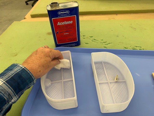
I blew out any dust and wiped down the inside with acetone
After painting epoxy inside the tank I took care to clean out the holes. I used West Systems 105 and 206.
Tubes will be glued in with hysol before the tank is closed up
The inside track of the mount was coated. If there is a fuel leak here I don't want the wood to be a sponge
After coating the inside I flipped the rear section over and coated the rear face. After the tank is closed I will only have to coat the top and sides.
Last edited by Viper1GJ; 04-01-2021 at 04:40 PM.
 04-01-2021, 04:38 PM
#87
Thread Starter
My Feedback: (20)
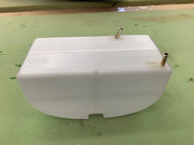
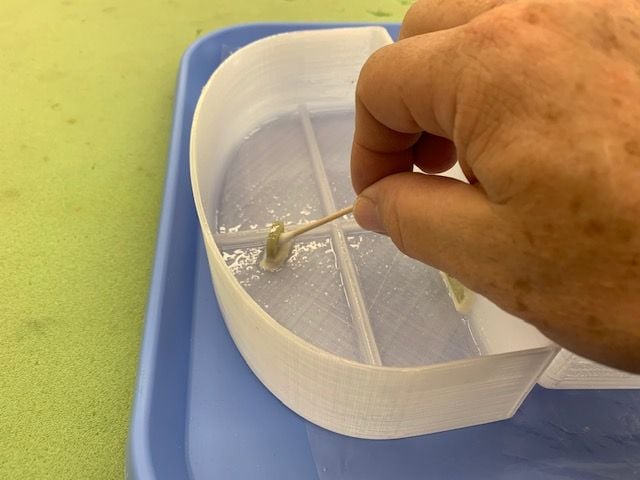
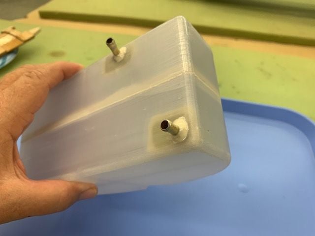
Closing up the tank
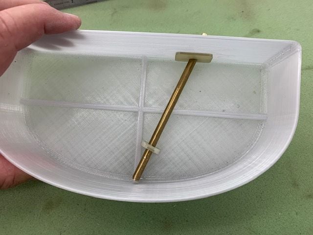
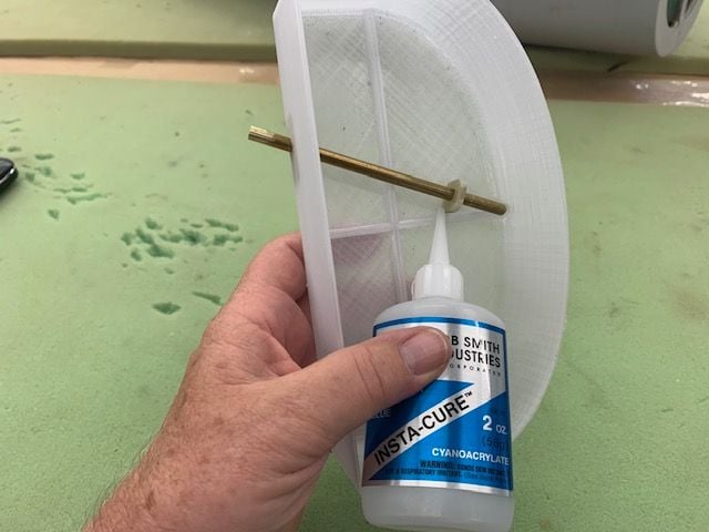
Fixed fuel tube and vent tube tacked in place with thin CA. Note there is no glue in the lower tube stand off because the tube is supposed to be able to flex and slip in the hole during flexing and expand and contraction.
Hysol applied to tube and tank joints inside and outside
Top of tank with fuel vent and fuel tube
After scuff sanding the tank joint again hysol was applied to the lap joint
A bead of epoxy was applied to both sides
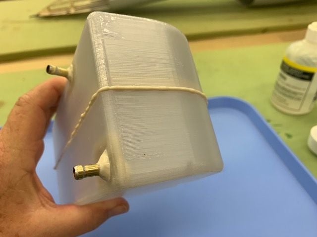
The tank was closed and glue squeezed out all the way around. Looks like a good seal.
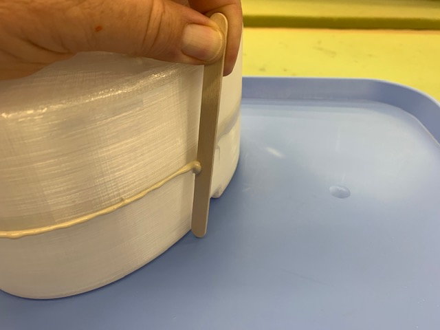
Excess scraped off with popsicle stick
Seam wiped with small squares of paper towel moistened with alcohol
Done for cure
Next step is to sand outside and apply fiberglass tape to joint line then coat the top and sides with epoxy.
Fixed fuel tube and vent tube tacked in place with thin CA. Note there is no glue in the lower tube stand off because the tube is supposed to be able to flex and slip in the hole during flexing and expand and contraction.
Hysol applied to tube and tank joints inside and outside
Top of tank with fuel vent and fuel tube
After scuff sanding the tank joint again hysol was applied to the lap joint
A bead of epoxy was applied to both sides
The tank was closed and glue squeezed out all the way around. Looks like a good seal.
Excess scraped off with popsicle stick
Seam wiped with small squares of paper towel moistened with alcohol
Done for cure
Next step is to sand outside and apply fiberglass tape to joint line then coat the top and sides with epoxy.
The following users liked this post:
Viper1GJ (04-02-2021)
04-02-2021, 04:21 AM
#91
Thread Starter
My Feedback: (20)
Last steps on tank build
Fiberglass tape tacked in place over lap joint with thin CA. This is probably not necessary due to the PETG material and lap joint but it's traditional!
Tank tubes taped off to keep them clean. West Systems epoxy on top of mount and outside tank to seal any possible pin holes. Keith says its probably not necessary but just a precaution.
04-02-2021, 04:13 PM
#92
Thread Starter
My Feedback: (20)
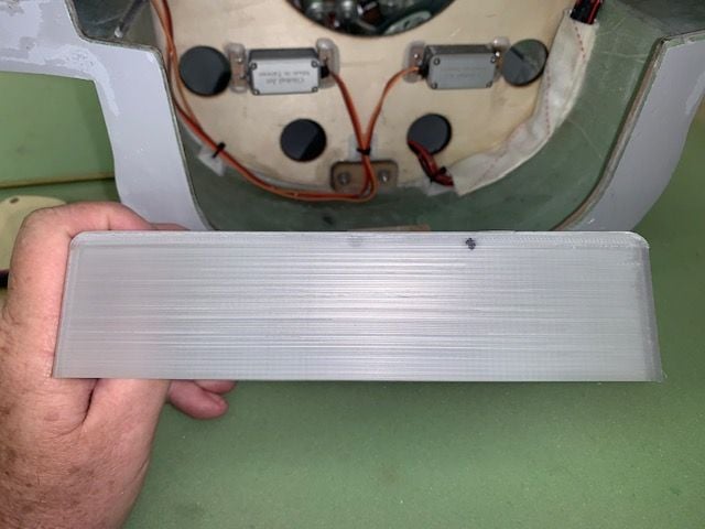
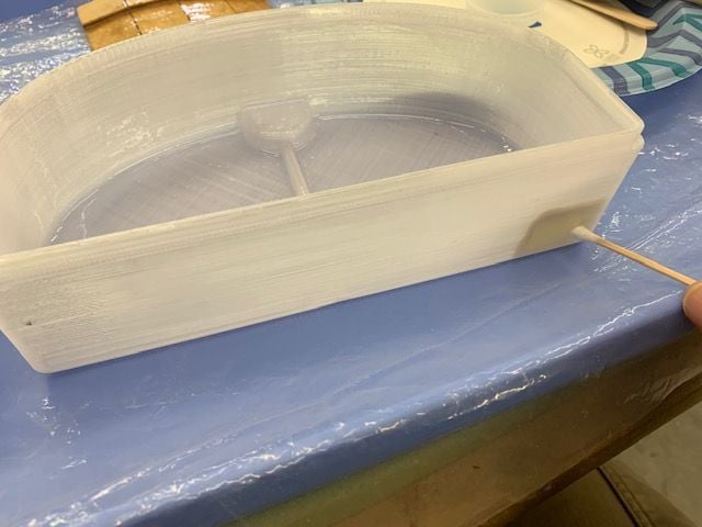
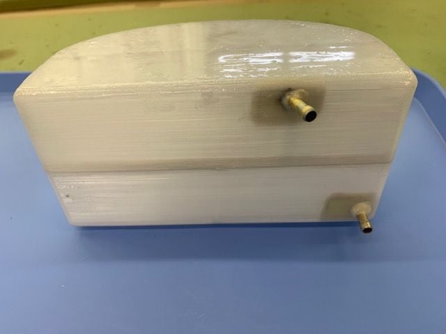
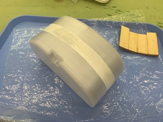
Tank Done!
I lightly wet sanded the tank surface with 220 grit wet sandpaper to smooth out the surface. Next step is glue in the tank mount.
I lightly wet sanded the tank surface with 220 grit wet sandpaper to smooth out the surface. Next step is glue in the tank mount.
Last edited by Viper1GJ; 04-03-2021 at 03:39 AM.
The following users liked this post:
Dansy (04-02-2021)
04-03-2021, 05:52 PM
#93
Thread Starter
My Feedback: (20)
Installing tank mount
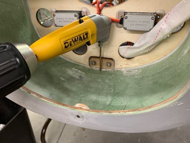
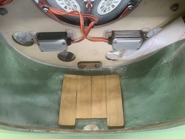
I always drill drain holes anywhere in the jet that can trap leaking fuel or oil. Don't ask how I learned to do this.
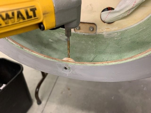
Front hole
View from bottom
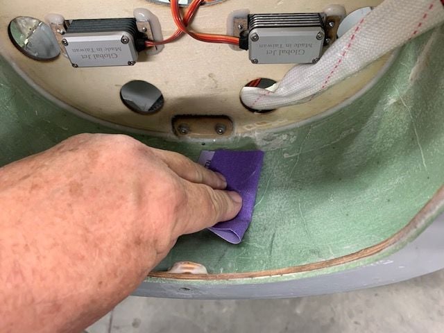
Scuff sanded inside the fuse where mount will sit
Scuff sanded bottom of tank mount
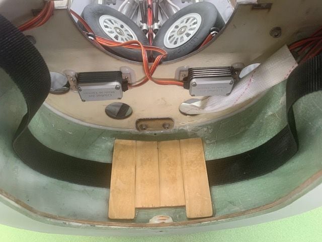
Wrapped a strip of plastic around tank strap to act as a release film so any epoxy that squeezed out and touched strap would not glue it in under the mount.
Applied tape loop strips to mount to hold in place on tank
Centered mount on bottom of tank and stuck it on with the tape strips
Wrapped strap around tank with plastic centered on mount and strap centered in the slot
Applied a thick layer of epoxy on front and rear sections of mount
Pressed tank into position centered and level with the top of the servo just behind the tank
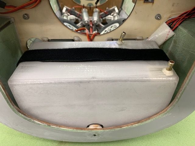
Six hours later, Presto! Strap pulled out with no issues.
Tank mount done. In the final install I will put a piece of 1/8" craft foam I stole from my wife's craft supplies between the mount and the tank to give a little padding and vibration/shock insulation.
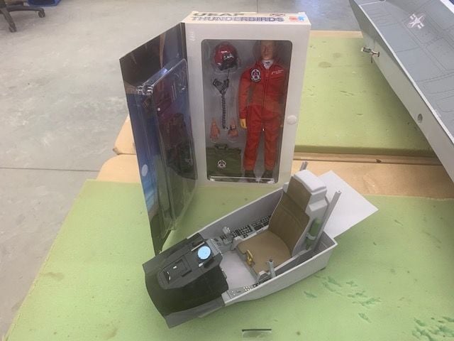
Was about ready to buy a pilot and I remembered this Tbird pilot I had for a project 20 years ago. I bought 2 at the time and this one is still in the box. Looks like this jet will have a red Tbird pilot.
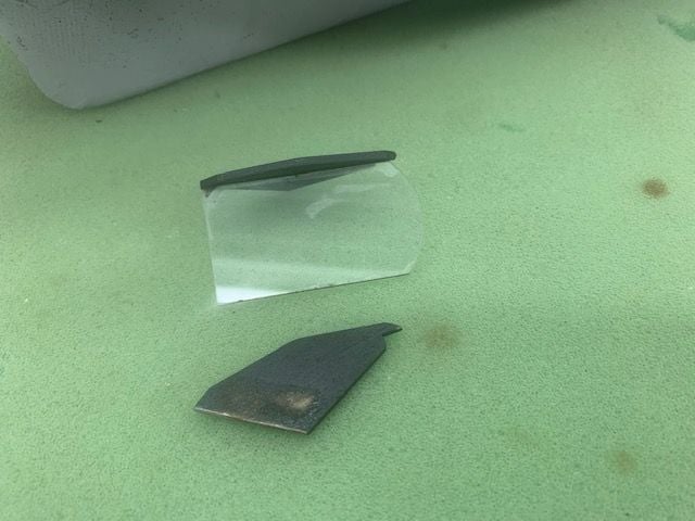
Found missing part of the HUD that was broken in shipping. It was stuck in the nose gear well and fell out when I took out the nose gear.
This is the last work on the jet for a week. I have to pay some RC dues with a spring break trip with wife and grandkids. Hope to collect some needed parts while gone for the week. To be continued...
Gary
I always drill drain holes anywhere in the jet that can trap leaking fuel or oil. Don't ask how I learned to do this.
Front hole
View from bottom
Scuff sanded inside the fuse where mount will sit
Scuff sanded bottom of tank mount
Wrapped a strip of plastic around tank strap to act as a release film so any epoxy that squeezed out and touched strap would not glue it in under the mount.
Applied tape loop strips to mount to hold in place on tank
Centered mount on bottom of tank and stuck it on with the tape strips
Wrapped strap around tank with plastic centered on mount and strap centered in the slot
Applied a thick layer of epoxy on front and rear sections of mount
Pressed tank into position centered and level with the top of the servo just behind the tank
Six hours later, Presto! Strap pulled out with no issues.
Tank mount done. In the final install I will put a piece of 1/8" craft foam I stole from my wife's craft supplies between the mount and the tank to give a little padding and vibration/shock insulation.
Was about ready to buy a pilot and I remembered this Tbird pilot I had for a project 20 years ago. I bought 2 at the time and this one is still in the box. Looks like this jet will have a red Tbird pilot.
Found missing part of the HUD that was broken in shipping. It was stuck in the nose gear well and fell out when I took out the nose gear.
This is the last work on the jet for a week. I have to pay some RC dues with a spring break trip with wife and grandkids. Hope to collect some needed parts while gone for the week. To be continued...
Gary
04-07-2021, 02:45 PM
#94
Nice looking Jet. did it come with a light controller? and will the gear/brake controller work the doors. I guess I should of asked these question, before I order one. please keep posting your build info and setups.
thanks
Terry G
thanks
Terry G
04-07-2021, 04:36 PM
#96
Thread Starter
My Feedback: (20)
Here is a link to a PDF that has everything you may want to know about the real ones:
https://www.nasa.gov/sites/default/f..._in_flight.pdf
My jet came with JP gear/door controller and a JP brake controller. It also came with a small light controller. I will use the JP gear controller for the gear but I will use the sequencer in my Jeti Tx to control the gear doors. I will be using an AG63 Anti-sideslip brake and steering gyro controller from GJC for brake and steering.
I plan to use the supplied light controller if I can figure it out but there is no instructions included. It's just a PC board and connector pins. I'll post some pics of the controllers when I get back home in a couple of days.
Gary
The following users liked this post:
f106jax (04-11-2021)
04-08-2021, 03:37 AM
#98
The following users liked this post:
ifly3d (04-08-2021)
04-09-2021, 11:00 AM
#99
My Feedback: (2)
Not to rerail Gary's build thread but I'm hoping my F-16XL will be ready for it's 1st flight next few days and before anyone asks lol both wing joints were strengthened with carbon along with the entire wing section were reinforced also with carbon and feels way better, rock solid.

04-09-2021, 05:08 PM
#100
Thread Starter
My Feedback: (20)
HI F900,
Post #1 says "Anything F-16XL welcome here!" Bring it on! Do you have pictures of the CF mods to the wing joints and wing sections? Please post if you have them.
I am back home today. "RC dues" paid up for a little while and everybody had fun. Looking forward to getting some shop time tomorrow and starting my wing joint mods. I think the existing wing joint assembly is probably good enough but I'm not sure so I'm adding some insurance.
I plan to laminate the inside fuse skin around the wing tube sleeves in CF to strengthen the fuse skin and former joint. Then I plan to add a sub former above and below the wing tube sleeve to directly transfer loads from the wing tube sleeve to the airframe structure similar to what Paul suggested in post #49. I am considering tying both the front and rear wing formers together with either a wood rib between them or CF laminate on the inside of the skin to distribute the wing tube load path between each former and the fuse skin. TBD till I can get another look at the inside of the fuse.
I made contact with Mike and Ralph at GJC this week. I'm very impressed with the their willingness to help solve issues an receive recommendations for improvements. Mike told me that Global Knight is also wanting to make improvements to the F-16XL. I really like this jet and want it to be successful and hopefully some ideas from this thread can be rolled into follow on kits. Ralph told me the replacement fuse decals have been ordered so I will proceed with the grey repaint this week mentioned in post #3.