


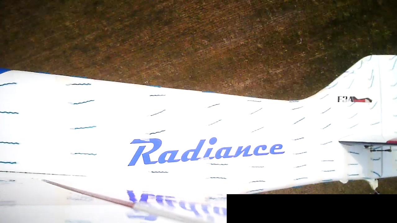
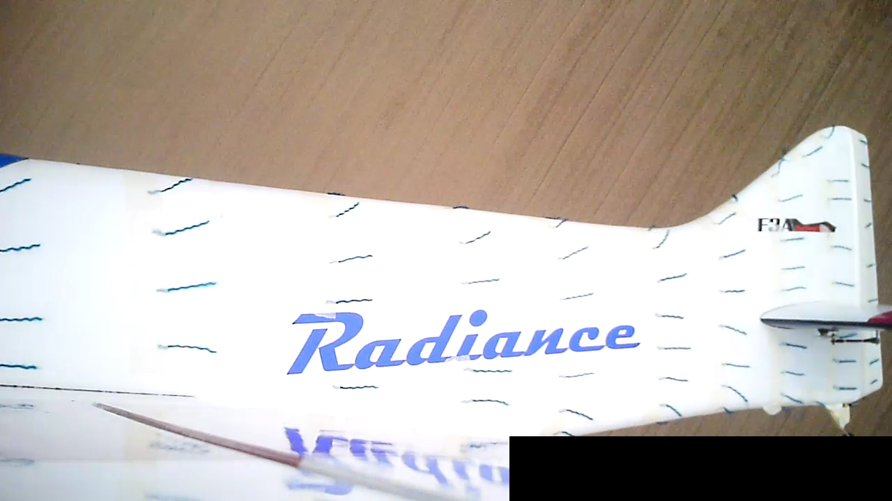
Airflow visualisation
 08-30-2013 | 08:10 PM
#26


My Feedback: (8)
Yeah it's funny, at work it took me a year to remember that commercial airplanes don't fly inverted (well we don't design engines for inverted flight), and now I work a lot so I have to remember that our models do 
I think torque results in yaw due to resultant use of trim tabs. I usually look at my Pilot's Encyclopedia of Aeronautical Knowledge for this stuff but I left it at work. Maybe if I actually were flying my airplanes I'd be thinking more about this stuff and not forgetting so easily :/
So it seems to me that prop wash is prevalent mostly at high power (need right thrust for vertical climbs, right rudder at takeoff, etc) and impacts the airplane the same if it's inverted or not (rudder is on bottom when inverted and air comes across from opposite direction, still needing right thrust/rudder to correct).
That is, if spiraling air really does exist.
 08-30-2013 | 08:14 PM
#27
My Feedback: (8)
Hey Alex, if you do the tufts again, can you put one at the top center of the vertical stab, and maybe one centered on the outside edge of the horizontal stab? It would be neat to see the rudder tuft being pushed to the side and the stab tufts being pushed up and down.
08-30-2013 | 10:06 PM
#28
Thread Starter
I don't think the goal is to prove whether spiral propeller slipstream exists or not, but to see what can be done to improve the knife edge behavior and rudder response. Obviously the contra drive offers many advantages, not only removing the need for right thrust.
I am curious though about what causes the need for so much right thrust in our models.
In extreme cases, like full rudder deflection at low speeds, the airflow around the vertical tail separates completely. Rudder still works, but the braking effect from the extra drag is quite visible:
To improve the airflow around the vertical tail, i plan to add 1-2 fin fences, then i will experiment with 15-20mm tall fuselages fences or strakes, which should stop the air leaking from the high pressure side to the low pressure side around the belly pan and turtle deck. It will look a little strange, but probably so did the canalisers when they were first introduced
08-30-2013 | 10:43 PM
#29
Please, this is pattern not gliders, so stop the empirical testing and collection of quantative data.
Just tell everyone the plane "presents" better and has greater rudder authority with the tuffs off wool and watch the competition follow the trend.........
Time to apply some shag pile to the Aries I think..(some red crushed velvet with corduroy paneling might become hip again)
Just tell everyone the plane "presents" better and has greater rudder authority with the tuffs off wool and watch the competition follow the trend.........
Time to apply some shag pile to the Aries I think..(some red crushed velvet with corduroy paneling might become hip again)
Last edited by bjr_93tz; 08-30-2013 at 10:46 PM.
08-31-2013 | 01:42 AM
#30
Please, this is pattern not gliders, so stop the empirical testing and collection of quantative data.
Just tell everyone the plane "presents" better and has greater rudder authority with the tuffs off wool and watch the competition follow the trend.........
Time to apply some shag pile to the Aries I think..(some red crushed velvet with corduroy paneling might become hip again)
Just tell everyone the plane "presents" better and has greater rudder authority with the tuffs off wool and watch the competition follow the trend.........
Time to apply some shag pile to the Aries I think..(some red crushed velvet with corduroy paneling might become hip again)
Pay little attention to stuff like that in the above post.
Keep up the great work ,especially if you are interested yourself. Those that are not interested do not HAVE to read it.
The demands from a pattern plane are high and very varied.
Knowledge is power. Understanding is a basic requirement.
The induced drag in the last two examples must be very high.
Also looking at them with 'lay man' eyes it seems to stand to reason that all that flow on both the low and high pressure sides must destabilise the model in high AOA KE manoeuvres - or - at least leave it unstable so prone to disturbance by small forces from the thrust source and or climate conditions.
I have been thinking about a fuz,, with very flat sides and small turtle decks/ flat bottom.
I think that with flat sides very small fences would do a lot and could done in such a way that the aesthetics are good.
Brian
Last edited by serious power; 08-31-2013 at 01:53 AM.
08-31-2013 | 05:53 AM
#31

My Feedback: (121)
Fascinating discussion!
Alex, are we to assume that there is no disturbance in the airflow on the bottom of the fuselage/rudder? It might be interesting to check there as well. I will be very interested to see the results of the fin and fuselage fences, perhaps you could test them seperately. The placement of the fuselage fences is interesting; they seem to have a very significant positive incidence, do you anticipate trim changes?
The right thrust question seems to have many variables. About 20 years ago I did some extensive empirical testing with a Hanno powered Runaround and discovered that the amount of right thrust needed (for that airplane) varied with the prop (12x11 vs 13x9) and violence of direction change (eg. pull up into a vertical line): less right thrust required for the 13x9 and smoother direction change. Of course, airspeed is probably the real culprit in this case, but the Runaround also has the wing placement very low on the fuselage (far from the C/L). More food for thought...
Lastly, the oil dispersion pattern on the bottom of my venerable MK Topstar powered by a piped, inverted OS 140RX is completely symmetrical. The prop is an APC 18.1x10.
Last edited by flywilly; 08-31-2013 at 05:57 AM.
08-31-2013 | 07:31 AM
#32

Interesting point, on my airplanes with the exhaust located at about 1" of the bottom.of the fuselage (always using 23% oil) it has never stained with oil any side of the fuselage just the stabs when the fumes open like a cone, never above the stabs, and it is always straight , there is about 5" of prop distance from the exhaust to the prop tip, never seen it spiraling in any way, and smoke is the other indicator used in wind tunnels.
Very interesting..
Very interesting..
08-31-2013 | 08:08 AM
#33
Senior Member
Joined: May 2005
Posts: 615
Likes: 0
Received 0 Likes
on
0 Posts
From: caracas, VENEZUELA
If the bottom of your fuses/stabs have oil residues is not the spiral slip stream to blame.... Your engine is too rich!
Now seriusly, exelent experiment. Congratulations!!
Now seriusly, exelent experiment. Congratulations!!
08-31-2013 | 08:38 AM
#34
Joined: Jul 2006
Posts: 2,819
Likes: 0
Received 0 Likes
on
0 Posts
From: Ossining,
NY
Whoever said spiraling air 'doesn't exist' is likely a Republican Scientist who moved to aerodynamics after disproving climate change.
Yeah, Joe, science is no place for skeptics, eh?! LOL
Thank goodness for guys like Alex who just want to find out what is happening without bringing politics or religion into the discussion.
Yeah, Joe, science is no place for skeptics, eh?! LOL
Thank goodness for guys like Alex who just want to find out what is happening without bringing politics or religion into the discussion.
08-31-2013 | 08:53 AM
#35
Hey Brian,
I think bjr-93tz was being facetious about stopping the testing and collecting of data. I believe what he was saying is that more pattern guys need to be doing stuff like Alex instead of just feeling good about the design of the latest pattern design that hits the street.
Jim O
I think bjr-93tz was being facetious about stopping the testing and collecting of data. I believe what he was saying is that more pattern guys need to be doing stuff like Alex instead of just feeling good about the design of the latest pattern design that hits the street.
Jim O
08-31-2013 | 11:33 AM
#37
Joined: Apr 2010
Posts: 169
Likes: 0
Received 0 Likes
on
0 Posts
From: Richmond, CA
Yo Ho this is a great experiment, thank you! PLEASE post links to clips of the raw video somewhere, too, as would love to see it in live action.
For all you SSS doubters, I am a spiral slipstream faithful - I admit. But mainly from the photographic evidence I've seen, some of which I share here. I always loved this picture (giant scale Cap 232):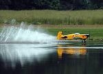
I am quite confident the prop itself never touched the water as if it had the wheels would have been so deep as not to bounce off the water. Therefore, the spiral is due to the spiraling of the airflow.
Another point: if you're looking at tufts such as these pictured to determine whether spiral slipstream affects the airframe, I don't believe you're looking at the right thing. The thrust vector that spiral slipstream creates which makes an aircraft change its path is not one that tufts would show since such a vector is perpendicular to the flight path on the horizontal plane (level flight); it pushes sideways against the rudder and fuselage, not so much up and down. The tufts only show airflow being deflected up and down. Last point - near the fuselage, spiral slipstream is the weakest. It's much more powerful at prop-tip distance from the centerline.
If you would like to use tufts to check for spiral slipstream, put a small wire mast on the turtledeck between the rudder and the canopy - the tip of which is about as high as the rudder - and attach a tuft to the tip. Attach your keychain camera to the top of the rudder. Check for lateral displacement of the tuft in powered uplines vs. neutral power downlines.
Roasting popcorn waiting for the videos!
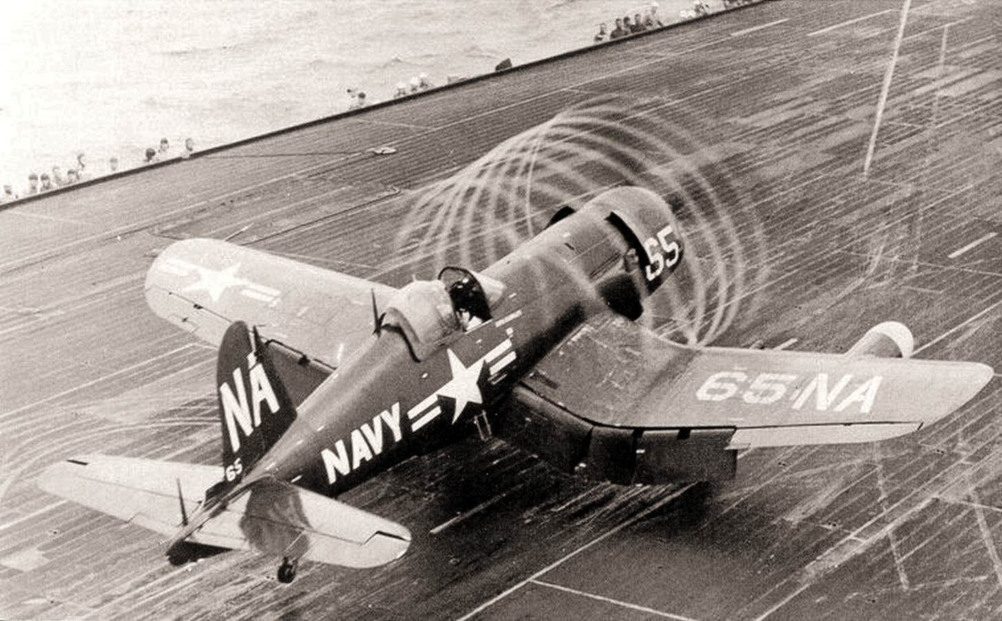
Just for fun, a couple other pictures of spiral slipstream from the full-size world. If you drill into the photo of the Corsair, you can see the prodigious amount of right rudder the pilot is applying (yes I know there is p-factor and gyroscopic precession in play as well).

Bill
For all you SSS doubters, I am a spiral slipstream faithful - I admit. But mainly from the photographic evidence I've seen, some of which I share here. I always loved this picture (giant scale Cap 232):
I am quite confident the prop itself never touched the water as if it had the wheels would have been so deep as not to bounce off the water. Therefore, the spiral is due to the spiraling of the airflow.
Another point: if you're looking at tufts such as these pictured to determine whether spiral slipstream affects the airframe, I don't believe you're looking at the right thing. The thrust vector that spiral slipstream creates which makes an aircraft change its path is not one that tufts would show since such a vector is perpendicular to the flight path on the horizontal plane (level flight); it pushes sideways against the rudder and fuselage, not so much up and down. The tufts only show airflow being deflected up and down. Last point - near the fuselage, spiral slipstream is the weakest. It's much more powerful at prop-tip distance from the centerline.
If you would like to use tufts to check for spiral slipstream, put a small wire mast on the turtledeck between the rudder and the canopy - the tip of which is about as high as the rudder - and attach a tuft to the tip. Attach your keychain camera to the top of the rudder. Check for lateral displacement of the tuft in powered uplines vs. neutral power downlines.
Roasting popcorn waiting for the videos!
Just for fun, a couple other pictures of spiral slipstream from the full-size world. If you drill into the photo of the Corsair, you can see the prodigious amount of right rudder the pilot is applying (yes I know there is p-factor and gyroscopic precession in play as well).
Bill
Last edited by n233w; 08-31-2013 at 12:26 PM.
08-31-2013 | 12:08 PM
#38
Just for fun, a couple other pictures of spiral slipstream from the full-size world. If you drill into the photo of the Corsair, you can see the prodigious amount of right rudder the pilot is applying (yes I know there is p-factor and gyroscopic precession in play as well). Quote !
Hi Bill,
You are correct to point out the rudder.
However 'p-factor and gyroscopic precession' are NOT in play. So the point you make re the rudder is even more valid re 'SSS'.
The p-factor and gyroscopic precession only come into play during pitch and or yaw changes.
The torque is in play but that is transferring into the deck via the UC.
Brian
Last edited by serious power; 08-31-2013 at 12:15 PM.
08-31-2013 | 12:32 PM
#39
Joined: Apr 2010
Posts: 169
Likes: 0
Received 0 Likes
on
0 Posts
From: Richmond, CA
Brian,
I beg to differ regarding gyro-p and p-factor. Gyro-p is very likely in play as the aircraft has very recently if not actually in the process of raising the tail; p-factor is in play as the aircraft is in a tail-low, positive angle of attack.
Maybe the forces involved in gyro-p and p-factor are not that great, however. The info at this link state: "Wind tunnel research on conventional single-engine aircraft indicate that about 6/7 of the total yawing moment is produced by the spiraling slipstream..." Unfortunately, the article itself shows no citations.
Thanks,
Bill
08-31-2013 | 01:29 PM
#40
Bill,
Ah ok.
Taking the point re the angle of attack - you are correct but the effect is very small as the speed range is from 0 to tail lift velocity.
There is no or very little airflow from the planes motion, it's all or nearly all from the prop. A high AOA (pitching moment) or yaw angle while the aircraft is already traveling at a high velocity is an other story altogether as a lot of air feeds in asymmetrically.
Taking your point re a pitching moment ,while the tail is lifting ;
This a negative pitching so the gyro-p acts opposite to how it does when the pitching moment is positive.
Brian
 08-31-2013 | 04:56 PM
#42
Joined: Apr 2010
Posts: 169
Likes: 0
Received 0 Likes
on
0 Posts
From: Richmond, CA
Bill,
Ah ok.
Taking the point re the angle of attack - you are correct but the effect is very small as the speed range is from 0 to tail lift velocity.
There is no or very little airflow from the planes motion, it's all or nearly all from the prop. A high AOA (pitching moment) or yaw angle while the aircraft is already traveling at a high velocity is an other story altogether as a lot of air feeds in asymmetrically.
Taking your point re a pitching moment ,while the tail is lifting ;
This a negative pitching so the gyro-p acts opposite to how it does when the pitching moment is positive.
Brian
Ah ok.
Taking the point re the angle of attack - you are correct but the effect is very small as the speed range is from 0 to tail lift velocity.
There is no or very little airflow from the planes motion, it's all or nearly all from the prop. A high AOA (pitching moment) or yaw angle while the aircraft is already traveling at a high velocity is an other story altogether as a lot of air feeds in asymmetrically.
Taking your point re a pitching moment ,while the tail is lifting ;
This a negative pitching so the gyro-p acts opposite to how it does when the pitching moment is positive.
Brian
Bill
09-01-2013 | 08:04 AM
#43
My Feedback: (3)
Just for fun, a couple other pictures of spiral slipstream from the full-size world. If you drill into the photo of the Corsair, you can see the prodigious amount of right rudder the pilot is applying (yes I know there is p-factor and gyroscopic precession in play as well). Quote !
Hi Bill,
You are correct to point out the rudder.
However 'p-factor and gyroscopic precession' are NOT in play. So the point you make re the rudder is even more valid re 'SSS'.
The p-factor and gyroscopic precession only come into play during pitch and or yaw changes.
The torque is in play but that is transferring into the deck via the UC.
Brian
Hi Bill,
You are correct to point out the rudder.
However 'p-factor and gyroscopic precession' are NOT in play. So the point you make re the rudder is even more valid re 'SSS'.
The p-factor and gyroscopic precession only come into play during pitch and or yaw changes.
The torque is in play but that is transferring into the deck via the UC.
Brian
I am pretty sure operational procedures on carriers include throttling up to full power as the gear (UC in your terms) touches the deck in case the arresting hook did not engage a wire. Since I don't see the tail hook, this is probably a take off run. That causes lots and lots of torque. Most WWII fighters had enough available torque on take off to be dangerous to the pilot if not properly applied and managed.
09-01-2013 | 09:25 AM
#44
I must admit I needed to Google this one. I was pretty sure Gyro Precession and P Factor were somewhat compensating in the air and P factor caused a left yaw when pulling up so the gyro precession must be to the right when pulling up. Therefore it must be to the left with the tail rising. So I looked it up and here is what I found:
There are 4 common forces we can apply on the propeller disk through control inputs, only two of which the average pilot must know. The four actions are rudder left/right or pitch up/down. The rudder actions can be ignored for non aerobatic pilots.
In either of these 4 actions we are driving a section of the blade into the wind and another away from, thus causing two forces to act on the disk. For example, let�s consider a pitching action typical of a tail wheel aircraft rolling down the runway. When a tailwheel aircraft picks up enough speed its tail is lifted off the runway by pushing the nose forward.
Let�s apply our two forces from this action: 1) We have taken a stick and pushed it against the top of the spinning propeller, that is our force to push the nose forward. 2) We have tied a string around the bottom of the spinning propeller and are pulling on that. So our forces, assuming sitting in the pilot seat, are a push on the top and a pull on the bottom.
Since the propeller rotates these forces will not act at the point of application, but instead 90 degrees (in the direction of disk rotation) from the point of application. From sitting in the pilot seat the propeller turns to the right and we know we have a push force on top and pull on the bottom currently. Let us rotate them 90 degrees to the right, giving us this result:
1) Push force on the right side of the disk 2) Pull force on the leftside of the disk 3) A left yaw has been produced
Any forward push on the yoke must be accompanied by a right rudder application (in flight also) to keep coordinated. Vice versa for a pull on the yoke. These actions are so subtle in a typical trainer that you will likely never recognize them during typical flight. I haven�t flown anything but aerobatic airplanes where I really noticed gyroscopic precession from pitching.
Hope this clarifies this subject.
Question: I was told the Brits had engines that rotated in the opposite direction. Was everything reversed on the Spitfire?
Jim O
09-01-2013 | 12:48 PM
#46
My Feedback: (8)
I think gyro is almost always present, just sometimes to a small degree. If the prop has any down/right thrust but the plane is flying straight and level, a force is being applied to the spinning disc and thus resulting in a gyro force. Obviously the forces are greater during pushes and pulls, or yaw. It is very difficult for anything to be perfectly aligned, so I imagine the gyro forces are there.
09-01-2013 | 04:32 PM
#47
It is to the left, not right, Gyro precesion applies to all rotation mass, when the plane of rotation is disturbed the applied force will act 90 degrees on the rotation orientation, when the tail lift, you can assume you are pushing the propeller disc from behind the top of the disc and 90 degrees will cause to yaw to the left as you are actually pushing the propeller disc from behind the right hand side. This is why the contra cancel the yaw as both propellers push or pull from both sides.
09-02-2013 | 12:25 AM
#48
Thread Starter
Fascinating discussion!
Alex, are we to assume that there is no disturbance in the airflow on the bottom of the fuselage/rudder? It might be interesting to check there as well. I will be very interested to see the results of the fin and fuselage fences, perhaps you could test them seperately. The placement of the fuselage fences is interesting; they seem to have a very significant positive incidence, do you anticipate trim changes?
Alex, are we to assume that there is no disturbance in the airflow on the bottom of the fuselage/rudder? It might be interesting to check there as well. I will be very interested to see the results of the fin and fuselage fences, perhaps you could test them seperately. The placement of the fuselage fences is interesting; they seem to have a very significant positive incidence, do you anticipate trim changes?
I'm working on the fin fences, hope to test them this weekend.
If you look at the horizontal flight images, you can see the airflow follows the approximate direction of the fuselage fences, so i hope they won't induce significant trim changes. The fuselage fences will only influence the airflow in KE position, hopefully in a good way
The late versions of the Spitfire had RR Griffon engines, which rotated in opposite direction to the Merlin engines used on the early versions.
09-02-2013 | 04:51 AM
#49
I must admit I needed to Google this one. I was pretty sure Gyro Precession and P Factor were somewhat compensating in the air and P factor caused a left yaw when pulling up so the gyro precession must be to the right when pulling up. Therefore it must be to the left with the tail rising. So I looked it up and here is what I found:
There are 4 common forces we can apply on the propeller disk through control inputs, only two of which the average pilot must know. The four actions are rudder left/right or pitch up/down. The rudder actions can be ignored for non aerobatic pilots.
In either of these 4 actions we are driving a section of the blade into the wind and another away from, thus causing two forces to act on the disk. For example, let’s consider a pitching action typical of a tail wheel aircraft rolling down the runway. When a tailwheel aircraft picks up enough speed its tail is lifted off the runway by pushing the nose forward.
Let’s apply our two forces from this action: 1) We have taken a stick and pushed it against the top of the spinning propeller, that is our force to push the nose forward. 2) We have tied a string around the bottom of the spinning propeller and are pulling on that. So our forces, assuming sitting in the pilot seat, are a push on the top and a pull on the bottom.
Since the propeller rotates these forces will not act at the point of application, but instead 90 degrees (in the direction of disk rotation) from the point of application. From sitting in the pilot seat the propeller turns to the right and we know we have a push force on top and pull on the bottom currently. Let us rotate them 90 degrees to the right, giving us this result:
1) Push force on the right side of the disk 2) Pull force on the leftside of the disk 3) A left yaw has been produced
Any forward push on the yoke must be accompanied by a right rudder application (in flight also) to keep coordinated. Vice versa for a pull on the yoke. These actions are so subtle in a typical trainer that you will likely never recognize them during typical flight. I haven’t flown anything but aerobatic airplanes where I really noticed gyroscopic precession from pitching.
Hope this clarifies this subject.
Question: I was told the Brits had engines that rotated in the opposite direction. Was everything reversed on the Spitfire?
Jim O
Sorry, I did not read this before my previous post.
09-02-2013 | 08:27 AM
#50
Senior Member
Joined: Sep 2009
Posts: 110
Likes: 0
Received 0 Likes
on
0 Posts
From: Manizales, COLOMBIA
I think nobody has ever denied the SSS existence. Honestly, whether if it exists or not is far away from the real core of the discussion in this thread. I think what Alex is doing is a remakable experiment and we are all very interested on seeing further tests (canalizers, SFG, strakes, different propellers, a contra, etc). The fact that a full size cap or a Zero show it has nothing to do with the discussion around pattern planes.
The real point here is if the SSS effect is enough to be considered as an issue on a 2m x 2m pattern plane, and if it is really worth the effort of fighting it (ok lets call it neutralizing) it with a contra, or a fin, or any other gadget.
I had the oportunity to see in person Mr Silvestri, Mr Trumpp, and Mr Mazuchelli fly their contras at the worlds a few weeks ago, and in my opinion (maybe an opinion not worth a lot since I did terribly bad on flying the preliminaries) is that they would have got much better scores without the contra than what they did with it (and hope my scores don't get worse in the future for saying this). I also did not watch a significant increase on the braking on behalf of the constant speeds. There were amazingly constant speed pilots flying with regular 2 blades or three blades.
In my opinion (again, maybe not very well qualified) Contras still need to work in two ways:
1. Weight, and therefore size. It is true that Seba's HeraS had to go for the Unk with 3900 mAh only for weight reasons. I think he managed his power superbly on an UNK on that wind with a mere 3900 mAh battery.
2. Solving the combination: propellers diameters, pitches and geometry, as there seems to be still some airflow innefficiencies while contrarotating. Most of the uplines are simply made at full power on a C50 (any C50 owner knows how much power you get at full power with this motor on a 2 blade prop).
I am not going to adress the Noise issue as this rule has become an absolute joke (sorry FAI but nowadays people seems to be competing on who halts the motor more to get the lowest noise on the noise test these days). Pilots can�t even hold their laughter on the noise circle.
I personally encourage and celebrate all sorts of innovation, wether they come out with positive results (you have to check for instance the control linkage of Mayr's Trigantic which are simply amazing and totally new, or the construcction and attachment system for the struts, also many details on Bryan's Alferma which are also very interesting) or maybe not so successful results (not worth mentioning).
Now regarding the contra, I still think there is a lot to be resolved yet and that has to come for the experts that are working on it. And even whan i was flying electric, there was a hidden winner again: YAMADA-SAN. I had never wished so much to have a YS inside my citrin as on Aug 21 / 2013 on a 30 Km/hr wind. Maybe Tuny (who I was calling for) can compliment a little on how was it to fly there with a YS 185 at full power on uplines.
Just a humble opinion form a pilot who still needs to learn a ton.
Marcelo Velez

