


Airflow visualisation

 09-16-2013 | 08:36 AM
#77
Thread Starter

Thanks Bob, I really hope this will be useful to others as well.
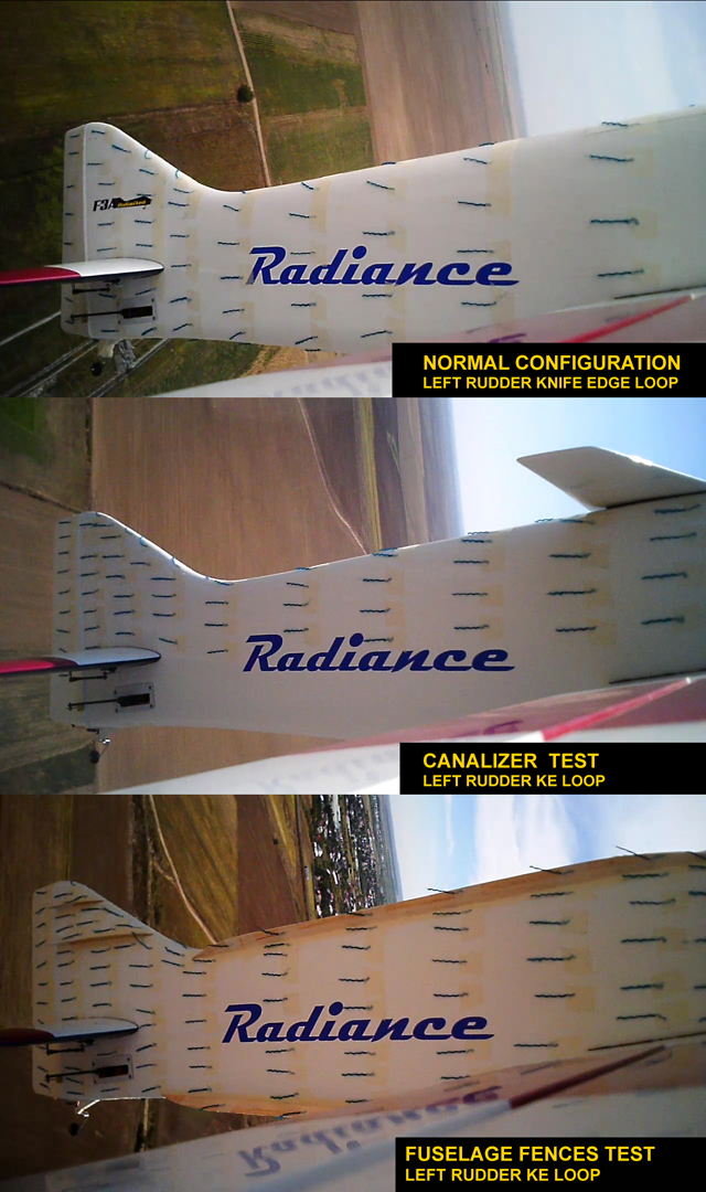
To sum up all the material presented before, I put together a few images to show the improvements in airflow for the canalizer and fuselage/fin fences.
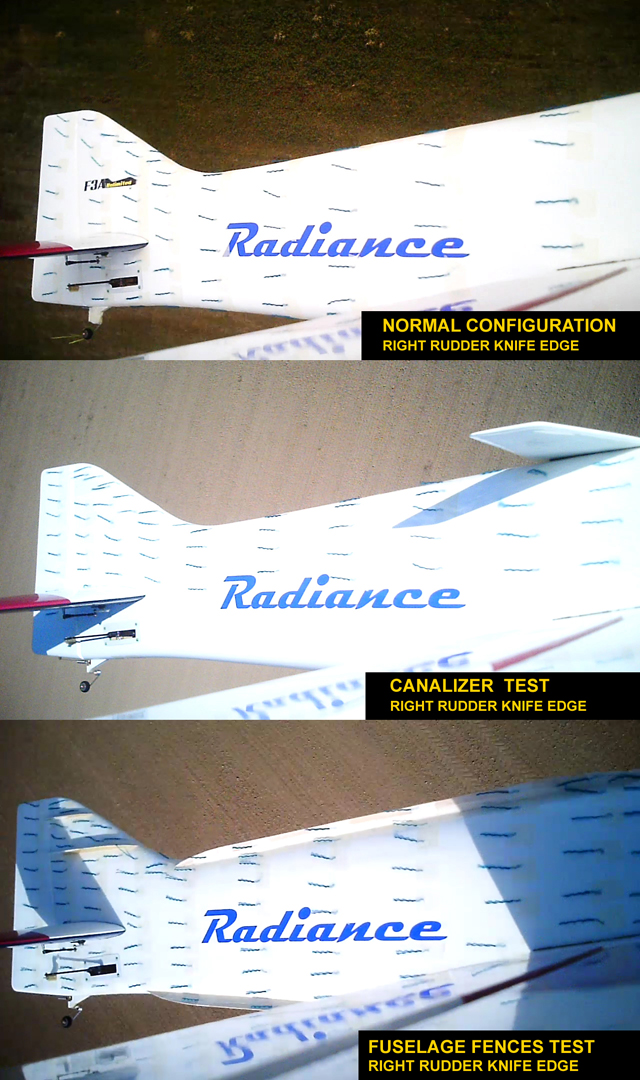
In Right Rudder KE maneuvers, the fuselage side facing the camera is the low pressure side. You can see in normal configuration there’s a strong spanwise flow on the vertical tail. This is not desirable because only the component of the velocity vector that is parallel to the flight path (green vector in the image below) is actually contributing to creating lift, meaning a less effective rudder.
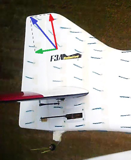
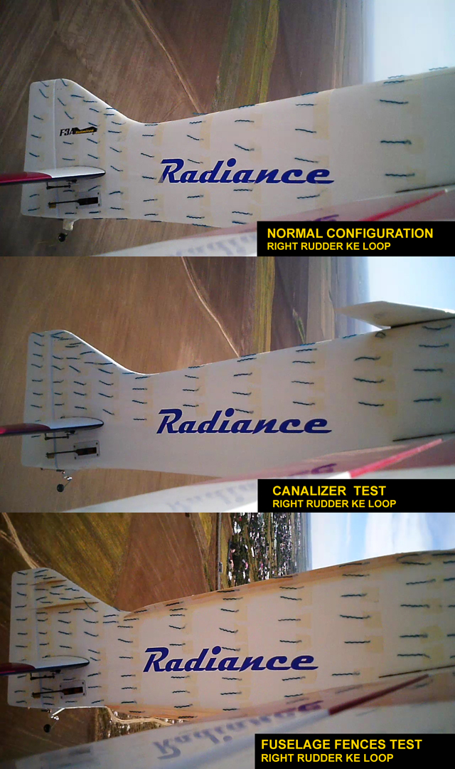
You can see in the comparison images below that the fin fences and canalizer are limiting the spanwise flow on the vertical tail, thus improving the rudder authority. In KE loops the canalizer seems slightly less efficient though, probably because it’s too far away from the fin to help in all situations.
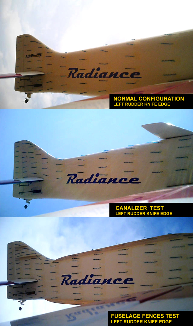
In Left Rudder KE maneuvers, the fuselage side facing the camera is the high pressure side. In normal configuration you can see from the direction of the tufts that the airflow is moving from the high pressure side to the low pressure side of the fuselage, going around the turtle deck and belly pan. This tendency of equalizing the pressures on both sides of the fuselage means a lower lift force provided by the fuselage in KE.
The canalizer does a pretty good job at limiting this effect, although you can see it doesn’t stop it completely. It only does half the job though, as there’s nothing to stop the air going around the belly pan to the low pressure side. Probably a canalizer at the bottom of the fuselage would help a lot, which seems to be confirmed by Isaac Najary’s tests with his canalizer/airbrake:
http://www.rcuniverse.com/forum/rc-p...jarylyzer.html
By looking at the tufts direction, I would say the fuselage fences are effectively stopping the air migrating from one side of the fuselage to the other, thus improving the fuselage lift and efficiency. It really felt like a major improvement in flight, reducing the fuselage incidence in horizontal KE by a large margin.
To sum up all the material presented before, I put together a few images to show the improvements in airflow for the canalizer and fuselage/fin fences.
In Right Rudder KE maneuvers, the fuselage side facing the camera is the low pressure side. You can see in normal configuration there’s a strong spanwise flow on the vertical tail. This is not desirable because only the component of the velocity vector that is parallel to the flight path (green vector in the image below) is actually contributing to creating lift, meaning a less effective rudder.
You can see in the comparison images below that the fin fences and canalizer are limiting the spanwise flow on the vertical tail, thus improving the rudder authority. In KE loops the canalizer seems slightly less efficient though, probably because it’s too far away from the fin to help in all situations.
In Left Rudder KE maneuvers, the fuselage side facing the camera is the high pressure side. In normal configuration you can see from the direction of the tufts that the airflow is moving from the high pressure side to the low pressure side of the fuselage, going around the turtle deck and belly pan. This tendency of equalizing the pressures on both sides of the fuselage means a lower lift force provided by the fuselage in KE.
The canalizer does a pretty good job at limiting this effect, although you can see it doesn’t stop it completely. It only does half the job though, as there’s nothing to stop the air going around the belly pan to the low pressure side. Probably a canalizer at the bottom of the fuselage would help a lot, which seems to be confirmed by Isaac Najary’s tests with his canalizer/airbrake:
http://www.rcuniverse.com/forum/rc-p...jarylyzer.html
By looking at the tufts direction, I would say the fuselage fences are effectively stopping the air migrating from one side of the fuselage to the other, thus improving the fuselage lift and efficiency. It really felt like a major improvement in flight, reducing the fuselage incidence in horizontal KE by a large margin.
Last edited by Alex Voicu; 09-16-2013 at 09:13 AM.
09-19-2013 | 04:19 PM
#78
My Feedback: (2)
http://youtu.be/9lhrs_GzhKw
http://youtu.be/9lhrs_GzhKw
http://youtu.be/rrFLqj4-e_M http://youtu.be/rrFLqj4-e_M
http://youtu.be/rrFLqj4-e_M http://youtu.be/rrFLqj4-e_M
Last edited by mithrandir; 09-19-2013 at 04:51 PM.
09-19-2013 | 04:42 PM
#79
My Feedback: (2)
I am gonna suggest the fences are in this instance behaving as vortex generators.... there is a pretty good AOA (wrt fences) and you are seeing the vortex.... but prolly no significant regions of seperation
Finally here are the results from the fin fences and canalizer test.
Since the airflow was almost symmetrical on the left and right sides of the fuselage in previous tests, I decided to tuft only the right side and concentrate on the rear fuselage and tail area. Fin fences obviously don�t have any influence on the airflow around the nose section, the canalizer may have but only for a small area on the canopy.
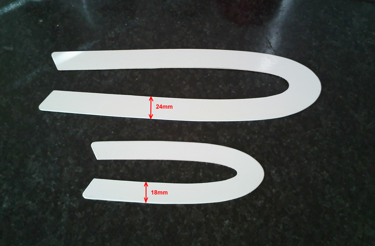
I initially built and tested 2 fin fences, shaped as seen in the image below. They have a constant width and follow the shape of the fin airfoil.
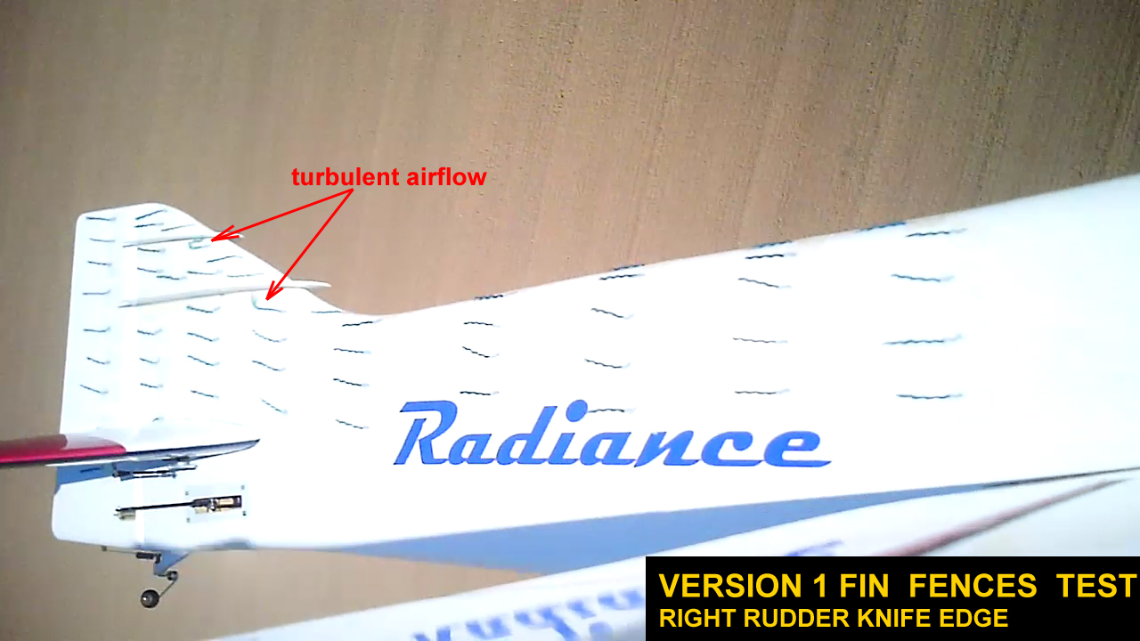
I expected some visible improvements in right rudder KE maneuvers, but the results were disappointing at first; in KE horizontal flight the spanwise flow was indeed limited by the fences in the trailing edge area, but I could see some turbulence near the leading edge, probably caused by the front end of the fin fences.
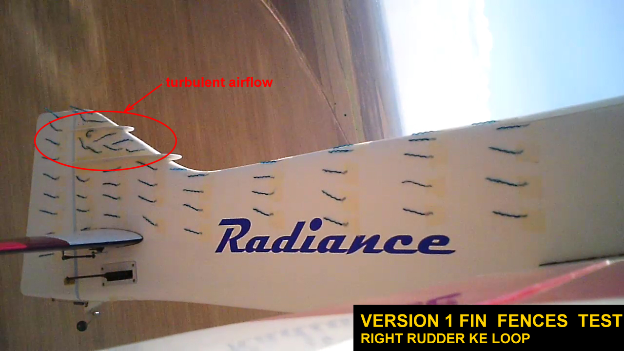
In KE loops it was much worse, you can actually see the disrupted airflow caused by the 2 fin fences:
Since the airflow was almost symmetrical on the left and right sides of the fuselage in previous tests, I decided to tuft only the right side and concentrate on the rear fuselage and tail area. Fin fences obviously don�t have any influence on the airflow around the nose section, the canalizer may have but only for a small area on the canopy.
I initially built and tested 2 fin fences, shaped as seen in the image below. They have a constant width and follow the shape of the fin airfoil.
I expected some visible improvements in right rudder KE maneuvers, but the results were disappointing at first; in KE horizontal flight the spanwise flow was indeed limited by the fences in the trailing edge area, but I could see some turbulence near the leading edge, probably caused by the front end of the fin fences.
In KE loops it was much worse, you can actually see the disrupted airflow caused by the 2 fin fences:
09-19-2013 | 08:08 PM
#80
Thread Starter
Yes the fin fences do much more than directing the airflow, but the fin tip does stall in high AOA knife edge maneuvers, probably because i used a thin airfoil. This is why i'm going to use thicker airfoils at the fin tip for my future designs. Fortunately i did just that for the kit version of Radiance (although for the wrong reasons)
 10-13-2013 | 03:57 AM
#81
Thread Starter
Encouraged by the big improvements in KE flight achieved with the test fuselage & fin fences presented in the previous posts, i built new ones and glued them on permanently. This time i made them longer, extending the fences on the canopy at the top and up to the motor cowl at the bottom. They are made of 1.5mm balsa, with carbon roving CA'ed along the outer edges and film covered. I put some transparent tape on the fuselage before attaching the fences with CA and canopy glue, so they can be removed later if necessary without damaging the fuselage covering.
The rudder power and fuselage lift in KE flight improved even more; as noticed before the fuselage needs a lot less incidence and rudder deflection in KE and the rudder power is just incredible. Knife edge loops, KE vertical 8s, KE triangles, they are all so easy to perform now, without ever needing full rudder deflection.
Compared to the canalizer tested earlier that influences the airflow only behind the canopy at the top of the fuselage, the fuselage fences are far, far more effective, obviously because they control the airflow over a much larger area, front and rear, top and bottom of the fuselage.
The test fences (the short version presented earlier, attached only to the rear fuselage) didn't induce any trim or mix changes, but the front part of the extended fences added just a little roll coupling in KE, probably because the bottom fences are a little longer. I added a few percents of rudder to aileron mix and now it tracks perfectly.
10-15-2013 | 09:28 AM
#82

Joined: Apr 2010
Posts: 169
Likes: 0
Received 0 Likes
on
0 Posts
From: Richmond, CA
All I can say is "Wow!" Your fences (or, as I think we could say, "strakes") are aesthetically attractive as well as effective. Has this never been successfully accomplished before? You may be at the tip of a major evolution! Might you be offering the kit with these devices?
Thanks,
Bill
Thanks,
Bill
10-15-2013 | 12:24 PM
#84
Thread Starter
Thanks, i'm glad you like them
Bill, if you're thinking about ordering a Radiance kit, i can talk to Tommie and we will include the fences in the box. But you can fit them to any existing design, it's really easy to build them.
Bill, if you're thinking about ordering a Radiance kit, i can talk to Tommie and we will include the fences in the box. But you can fit them to any existing design, it's really easy to build them.
10-15-2013 | 01:44 PM
#85

When I first saw this thread it got me interested in just what a T does, hence the T can thread I started. With all the different shapes and sizes of them I thought about trying some on my Epic, but the fences had also crossed my mind.
I don't remember exactly, but in 07 or 08 at the Nats I was lucky enough to be at the right place/right time when a classic pattern plane showed up at the hotel. It was going to go into the AMA museum, but something fell through. After some discussion with the owner, I ended up with it. When I first saw it, the 2nd thing that caught my attention were the fences on the fuselage. Now this is a mid-70's design, but purely unique. So what was the 1st thing that caught my eye.... it is a Delta wing. Now, before I knew who designed it, I thought is was just someone's attempt at pattern who didn't care about actually doing anything that looked like pattern. Once I found out who designed it, I started to wonder the why's of everything. I didn't get to ask Nat Penton everything I was curious to know about when I talked to him about it, but I plan on getting it flying again at some point.
Thank you Alex for your testing of all these set-ups!
10-15-2013 | 04:35 PM
#86
My Feedback: (121)
Hi Alex,
Great work and thanks again for sharing the results of your efforts!
One final question, hopefully: do you think dimensional optimization (changing length and/ or height) of the strakes (fences) would eliminate the need for mixing while still providing optimum benefit to knife edge flight?
PS Very cool airplane Jason, I remember seeing photos of it and wishing Nat would publish the design along with an explanation of the features.
10-15-2013 | 11:37 PM
#87
Thread Starter
That's an intriguing design Jason, thanks for the pictures. I'm curious about the reasons for using a delta wing on a pattern model.
I'm sure with some more testing it's possible to optimize the fences dimensions and remove the small roll coupling. The model had a little roll coupling before, but it was so small that i didn't even bother to mix it out. The fences just made it more noticeable. Anyway, i'll gladly trade a few percents of mix for the much improved KE performance.
I'm sure with some more testing it's possible to optimize the fences dimensions and remove the small roll coupling. The model had a little roll coupling before, but it was so small that i didn't even bother to mix it out. The fences just made it more noticeable. Anyway, i'll gladly trade a few percents of mix for the much improved KE performance.
Last edited by Alex Voicu; 10-16-2013 at 12:12 AM.
10-16-2013 | 03:13 AM
#89
Thread Starter
Hi Brian,
the model has a slight tendency to roll out of the knife edge flight (come back to horizontal). As mentioned above, it had this roll coupling before, but it was very small, close to 0.
the model has a slight tendency to roll out of the knife edge flight (come back to horizontal). As mentioned above, it had this roll coupling before, but it was very small, close to 0.
10-16-2013 | 03:21 AM
#90
All I can say is "Wow!" Your fences (or, as I think we could say, "strakes") are aesthetically attractive as well as effective. Has this never been successfully accomplished before? You may be at the tip of a major evolution! Might you be offering the kit with these devices?
Thanks,
Bill
Thanks,
Bill
10-16-2013 | 03:29 AM
#91
Hi Alex,
This would suggest that the flows/losses were greater off the top of the fuz than off the bottom in KE before the fence was installed - which makes sense !.
This is all pointing to a suggestion that flat sides , c/w fences, are the way to go - maybe even slightly concave.
The fuz should be a slice out of a constant cord wing with fences added to compensate for the short span - not pretty.
The current rounded top and bottom decks are just reducing effective span.
Brian
This would suggest that the flows/losses were greater off the top of the fuz than off the bottom in KE before the fence was installed - which makes sense !.
This is all pointing to a suggestion that flat sides , c/w fences, are the way to go - maybe even slightly concave.
The fuz should be a slice out of a constant cord wing with fences added to compensate for the short span - not pretty
.The current rounded top and bottom decks are just reducing effective span.
Brian
10-16-2013 | 03:59 AM
#92
Thread Starter
I think you're right Brian, we also have the wing which is closer to the bottom of the fuselage and probably limits the flow losses.
The fuselage design that you described would be very efficient but indeed not very pretty. But i think it is possible to integrate the fences in a new composite fuselage design with increased efficiency, without compromising the looks of the model.
The fuselage design that you described would be very efficient but indeed not very pretty. But i think it is possible to integrate the fences in a new composite fuselage design with increased efficiency, without compromising the looks of the model.
10-16-2013 | 06:09 AM
#93
Junior Member
Joined: Dec 2012
Posts: 15
Likes: 0
Received 0 Likes
on
0 Posts
From: KIEV, UKRAINE
Hi Alex!
Excellent work and interesting results.
May be it�s a result of improved vertical stab efficiency? You installed fences asymmetrically - only on the top part of the vertical stab. So this part generates a weak turning force. Correct me if I�m wrong.
Happy landings!
Sergey
Excellent work and interesting results.
Happy landings!
Sergey
10-16-2013 | 06:42 AM
#94
I think you're right Brian, we also have the wing which is closer to the bottom of the fuselage and probably limits the flow losses.
The fuselage design that you described would be very efficient but indeed not very pretty. But i think it is possible to integrate the fences in a new composite fuselage design with increased efficiency, without compromising the looks of the model.
The fuselage design that you described would be very efficient but indeed not very pretty. But i think it is possible to integrate the fences in a new composite fuselage design with increased efficiency, without compromising the looks of the model.
I think that it might be worth sacrificing some 'looks' if the function dividend is high enough.
F1 cars have their own beauty and bear nearly no resemblance to a GT at this stage.
It might be time for a leap of faith !!
.Brian
PS; Quantas has a good point also
10-16-2013 | 07:32 AM
#95
Thread Starter
Hi Alex!
Excellent work and interesting results.
May be it’s a result of improved vertical stab efficiency? You installed fences asymmetrically - only on the top part of the vertical stab. So this part generates a weak turning force. Correct me if I’m wrong.
Happy landings!
Sergey
Excellent work and interesting results.
May be it’s a result of improved vertical stab efficiency? You installed fences asymmetrically - only on the top part of the vertical stab. So this part generates a weak turning force. Correct me if I’m wrong.
Happy landings!
Sergey
It could be as you say, but i should have noticed the roll coupling earlier.
As you can see on page 3, i first tested the fin fences, without adding anything to the fuselage. I don't remember them having any influence on roll coupling.
The short version of the fuselage fences (presented on page 3 as well) also didn't add any significant roll coupling. I only noticed this when adding the longer fuselage fences.
10-16-2013 | 08:55 AM
#96
Junior Member
Joined: Dec 2012
Posts: 15
Likes: 0
Received 0 Likes
on
0 Posts
From: KIEV, UKRAINE
Alex, agree with you. Your experience with fin only fences / short fuse fences is a strong point. The extended nose part fences seems to be a problem. What do you think about spiral airflow from the prop? It looks like a cone with highest speed and pressure especially in the nose part. It seems that short version of your fences is a better solution – less influence of spiral airflow.
It would be interesting how your extended fences interact with coaxial propulsion system generating less spiral flow?
Of cause, it’s only assumption.
Sergey
It would be interesting how your extended fences interact with coaxial propulsion system generating less spiral flow?
Of cause, it’s only assumption.
Sergey
10-16-2013 | 09:45 AM
#97
Thread Starter
Sergey, i'd rather keep the fences as they are, the front part increased knife edge performance even more and a couple of percents of mix is really not a tragedy. It's not that uncommon for a pattern model to use a little rudder to aileron mix.
I really have no idea about the propeller spiral flow, tufts doesn't indicate anything about its existence but the speeds and pressures may still be different on fuselage sides.
I really have no idea about the propeller spiral flow, tufts doesn't indicate anything about its existence but the speeds and pressures may still be different on fuselage sides.
10-16-2013 | 11:10 AM
#98

Senior Member
My Feedback: (1)
.... a delta-winged pattern ship from the 70�s - with fuselage fences... wow.
This gets me really curious. I would love to see some more photos and, if available, hear details Mr. Penton had in mind when he designed that bird. Any information if it was ever entered into a pattern contest?
This gets me really curious. I would love to see some more photos and, if available, hear details Mr. Penton had in mind when he designed that bird. Any information if it was ever entered into a pattern contest?
10-16-2013 | 11:31 AM
#99
ALex
to remove the proverse roll coupling ,move the c/g back and Or reduce the positive inc. in the wing. One or both ,may be required to fix it. Doing a K/E loop exit is where you want to fine tune this adjustment for best results.
Proverse roll will increase when the main wing inc. is above .8 positive and more so if the CG is forward of 25%
Bryan

