


Home made YJ Jeep
 01-17-2025 | 01:16 PM
#1
Thread Starter

I'll do a brief step by step in my making of a YJ from scratch this project started years ago, and then I scrapped most of what I made, and restarted. I'll break it up into separate posts to make it easier to navigate I originally meant to make this as I was making it, but well I got caught up in working on it, and forgot >.> I'm a little absent minded like that.
The base of the vehicle is a frankensteined SCX10, and HPI wheely king I made
Here is an old picture(and what I started with)
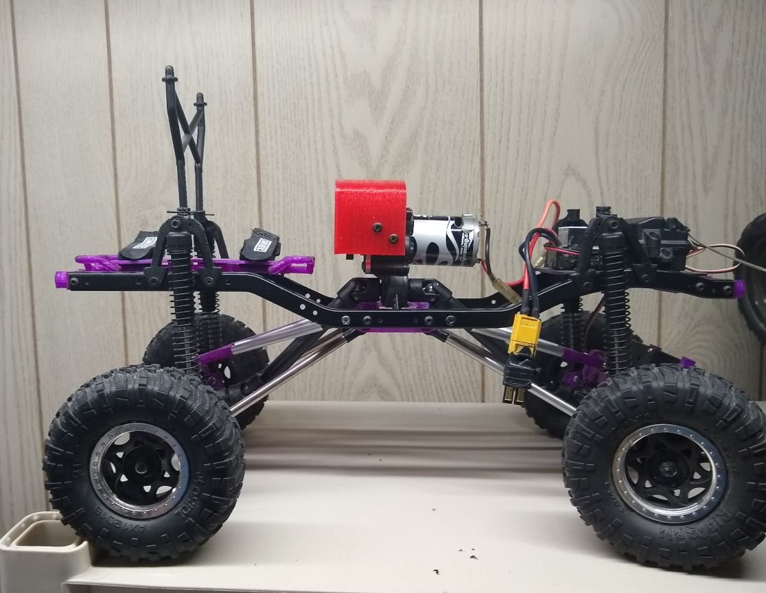
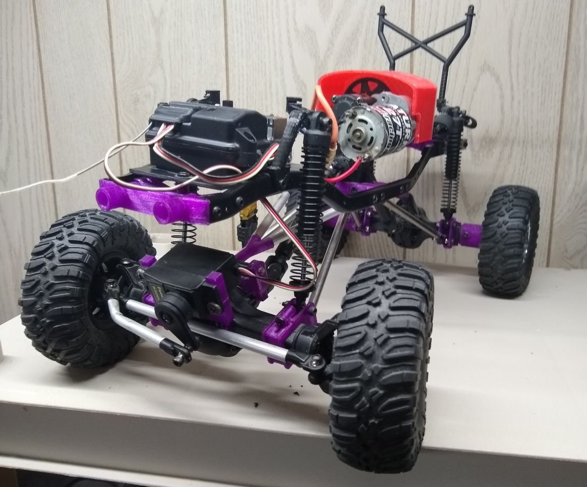
It has an Axial SCX10 frame a wheely King transmission, and axles, and at this time Wheely king shocks, and a pile of custom made 3d parts I designed along with custom made links. The driveshafts, and connectors to the axles are traxxas(I forgot the part number as I started this 10 years ago).
Then 6-7 years ago I found a YJ body file someone made, printed it(I had to do it in 6 parts due to how it was made), and honestly hated it... I threw it on a shelf after making it, and forgot about it. I don't have any pictures of it as I hated it so much, and honestly it was so poorly assembled it actually fell apart when I threw it in the trash.
The base of the vehicle is a frankensteined SCX10, and HPI wheely king I made
Here is an old picture(and what I started with)
It has an Axial SCX10 frame a wheely King transmission, and axles, and at this time Wheely king shocks, and a pile of custom made 3d parts I designed along with custom made links. The driveshafts, and connectors to the axles are traxxas(I forgot the part number as I started this 10 years ago).
Then 6-7 years ago I found a YJ body file someone made, printed it(I had to do it in 6 parts due to how it was made), and honestly hated it... I threw it on a shelf after making it, and forgot about it. I don't have any pictures of it as I hated it so much, and honestly it was so poorly assembled it actually fell apart when I threw it in the trash.
 01-17-2025 | 01:27 PM
#2
Thread Starter
Well unlike the last attempt I mentioned this attempt at the wrangler I found a new model that had most of the parts separated. Like the door handles, latches, fender flares they were all in their own separate file which made it easier to work with. I had to hollow out the model, and I split the main body into 3 pieces which are screwed together. Same with the fender flares they are screwed on. Hell I think I have more screws holding the fender flares on my model jeep then a real jeep has holding them on.


This was step one the front is held onto the middle section with 6 screws with nuts, the rear is held on with I think 14 screws, and the fenders are 11 or so per side(the front piece is split in 2 as my print bed wasn't big enough) The hood is on loosely for now.
This took me about a week to print...
I'm also happy I made it assemble like this reason will be shown later.
01-17-2025 | 01:32 PM
#3
Thread Starter
I then proceeded to design it a custom front and rear bumper based on pictures I saw. (btw I used tinker cad for all the work. Thinks I have made in it has blown the mind of one of my old time buds away)
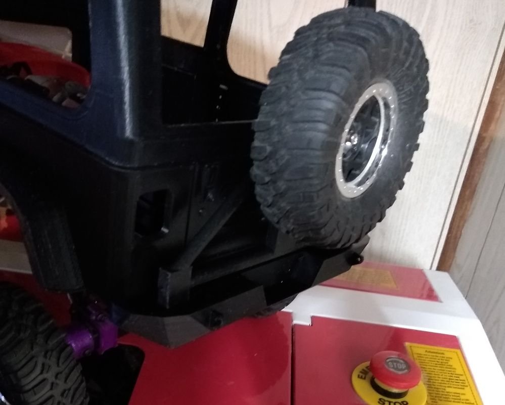

The rear bumper was based on one I saw on Amazon for sale for real jeeps, and the front was based on what I saw were stock YJ's
The rear bumper was based on one I saw on Amazon for sale for real jeeps, and the front was based on what I saw were stock YJ's
01-17-2025 | 01:38 PM
#4
Thread Starter
Now comes why I was happy I made the thing in 3 sections as I did
I hated the hood, and front end
So I spent an hour or 3, and redesigned them to open properly, and while I was at it I made working hinges to secure it.


turns out I had some tiny 2mm screws from a project that the heads were basically a perfect size to look like scale bolts which is what I used to hold them on along with all of the trim pieces . Like the 3d file I used had little bolt heads, and when I measured them the screws I used were less then 0.1mm's larger so yea. all the hinges, and parts are screwed on(except on the rear those have screws, but are part of the body the screws are purely decoration on the tail gate)
I hated the hood, and front end
So I spent an hour or 3, and redesigned them to open properly, and while I was at it I made working hinges to secure it.
turns out I had some tiny 2mm screws from a project that the heads were basically a perfect size to look like scale bolts which is what I used to hold them on along with all of the trim pieces
. Like the 3d file I used had little bolt heads, and when I measured them the screws I used were less then 0.1mm's larger so yea. all the hinges, and parts are screwed on(except on the rear those have screws, but are part of the body the screws are purely decoration on the tail gate)
01-17-2025 | 01:47 PM
#5
Thread Starter
Next step was headlights, and turn signals
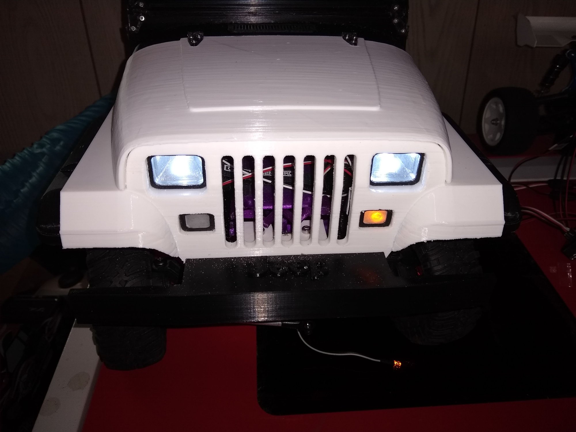
I went looking for something in a box, and found some axial SCX10 parts, and saw 2 fog lamps, and was like those would be perfect, so I made a fast bracket, and screwed them into the front bumper in the approximate spot they would go on a real YJ

I also made the tail lights.

The RC off

RC at a stop with left turn signal blinking (it appears better in person) There are 3 LED's in each rear brake light stop/dim for headlights being on, turn, and reverse.
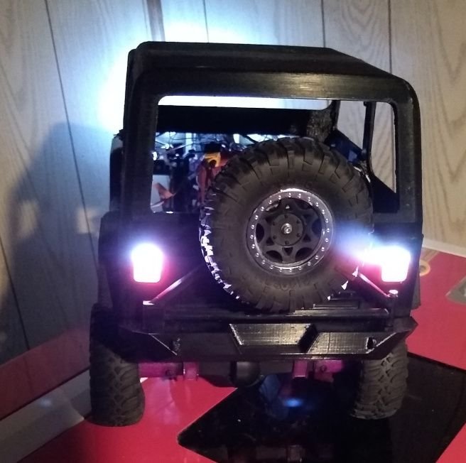
The RC in reverse.
The headlight lenses were made from a Costco pie containers top piece which was clear plastic. To frost it for the front turn signals, and rear lights I took 800 grit sandpaper and sanded it in circles.
For the rear brake lights I then took red sharpie and colored in the brake signal section while leaving the reverse area untouched.
I friction fit the light buckets into the body, and together. There are screw holes I could use but the fit is so tight it takes way more force to knock em out then the RC will ever see.
I went looking for something in a box, and found some axial SCX10 parts, and saw 2 fog lamps, and was like those would be perfect, so I made a fast bracket, and screwed them into the front bumper in the approximate spot they would go on a real YJ
I also made the tail lights.
The RC off
RC at a stop with left turn signal blinking (it appears better in person) There are 3 LED's in each rear brake light stop/dim for headlights being on, turn, and reverse.
The RC in reverse.
The headlight lenses were made from a Costco pie containers top piece which was clear plastic. To frost it for the front turn signals, and rear lights I took 800 grit sandpaper and sanded it in circles.
For the rear brake lights I then took red sharpie and colored in the brake signal section while leaving the reverse area untouched.
I friction fit the light buckets into the body, and together. There are screw holes I could use but the fit is so tight it takes way more force to knock em out then the RC will ever see.
01-17-2025 | 02:01 PM
#6
Thread Starter
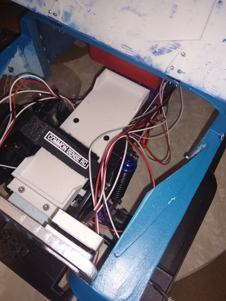
in the last picture in the prior post you can see a rats nest of wires from how I kinda just haphazardly wired it so I decided it was time to clean it up, and mount the electronics better then they originally were.
This was my solution
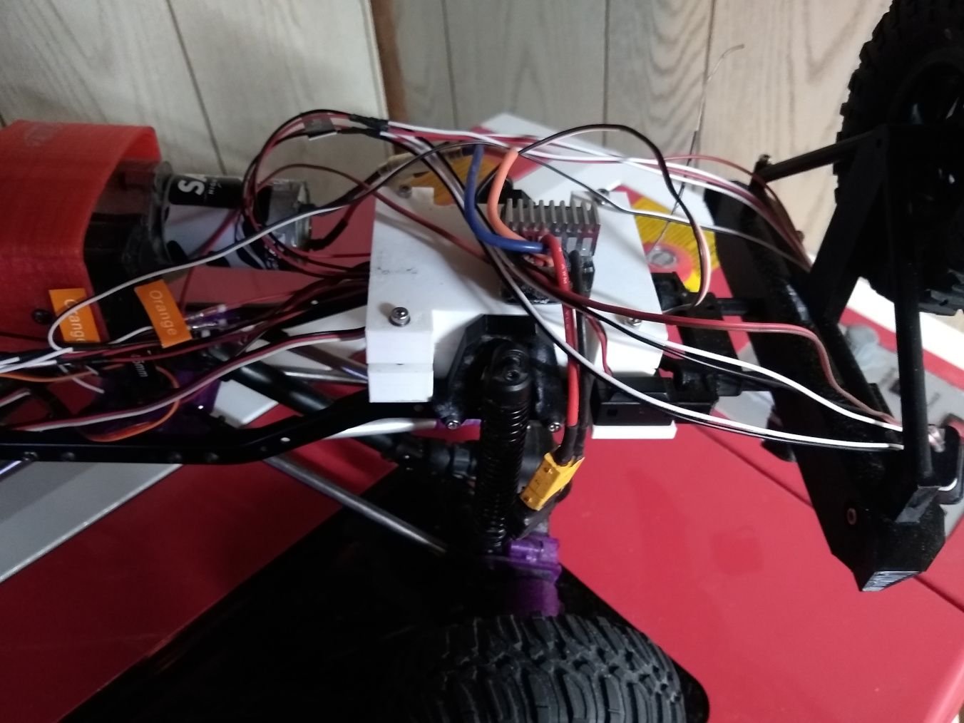
It is a box I made to hold the LED controller, and the RX. I designed it to wrap around the rear shock towers.
The rear shock toweres also were redesigned for this to allow it to go on easy as I removed the body mounts as they are not needed for this RC, and also to make it stronger as one of the old shock towers were broken due to how thin the mounting tab was. The redesign made the tabs 4x thicker to where I doubt they will ever break. The front also has a new design based on the rears.
The box is made to be as water tight as I could get it. I made it in 2 halves, and took door, and window sealing tape, and put a strip on the top, and bottom with 4 screws (one in each corner) to hold it shut. This allowed me to easily put the pile of wires through.
How water tight is it? I don't know, but it would at least prevent any water getting in outside total submersion to which there is a high chance it wouldn't leak for a foot or 2 due to how much I compressed the sealing tape when I screwed the top to the bottom.
I also put the power switch for the ESC in an easily accessible location right behind the rear shock tower. I'm thinking of looking for a rubber piece I know I had somewhere on a RC to cover it from liquid, and debris though.
This was my solution
It is a box I made to hold the LED controller, and the RX. I designed it to wrap around the rear shock towers.
The rear shock toweres also were redesigned for this to allow it to go on easy as I removed the body mounts as they are not needed for this RC, and also to make it stronger as one of the old shock towers were broken due to how thin the mounting tab was. The redesign made the tabs 4x thicker to where I doubt they will ever break. The front also has a new design based on the rears.
The box is made to be as water tight as I could get it. I made it in 2 halves, and took door, and window sealing tape, and put a strip on the top, and bottom with 4 screws (one in each corner) to hold it shut. This allowed me to easily put the pile of wires through.
How water tight is it? I don't know, but it would at least prevent any water getting in outside total submersion to which there is a high chance it wouldn't leak for a foot or 2 due to how much I compressed the sealing tape when I screwed the top to the bottom.
I also put the power switch for the ESC in an easily accessible location right behind the rear shock tower. I'm thinking of looking for a rubber piece I know I had somewhere on a RC to cover it from liquid, and debris though.
Last edited by SyCo_VeNoM; 01-17-2025 at 02:37 PM.
01-17-2025 | 02:05 PM
#7
Thread Starter
Anyways now that all that was done I decided to paint it
I bought some cheap acrylic paint set off amazon that had a pile of colors tried a few, and ended up painting it acid blue that I mixed a tiny bit of metallic silver (I had a old parma bottle from years back) in to give it a slight shimmer in person.
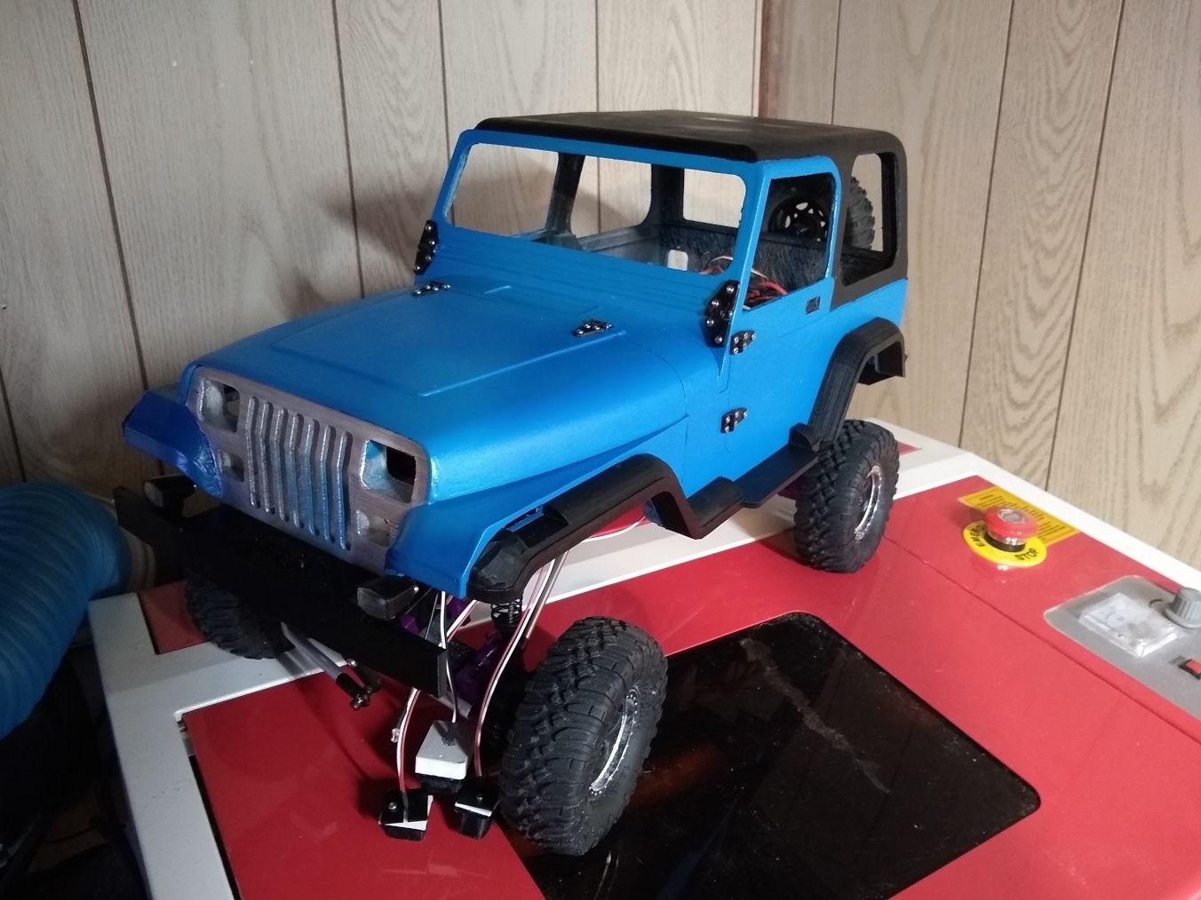
After I took this picture I resprayed the front grill as in person I didn't see it was blue
I bought some cheap acrylic paint set off amazon that had a pile of colors tried a few, and ended up painting it acid blue that I mixed a tiny bit of metallic silver (I had a old parma bottle from years back) in to give it a slight shimmer in person.
After I took this picture I resprayed the front grill as in person I didn't see it was blue
01-17-2025 | 02:16 PM
#8
Thread Starter
I then made windows for it. I originally had the plan to laser cut acrylic, make custom 3d printed mounting brackets, and on hour 2 of making a template I said screw it(well the real word started with f...) grabbed the rest of the costco pie container top, a pair of scissors, and cut em out. Then grabbed a hot glue gun to hold them in, and honestly I am quite happy with the results
Well with it painted, wired up, and having windows I still wasn't happy with some things
Namely I hated how it sat with the stock wheely king shocks
So I ordered a set of 70mm shocks which from what I saw are the same length as scx10 shocks which brought the ride height down a lot(I think the WK were 120mm >.> ), makes it look better, and it also isn't wobbly anymore... The WK shocks the body would sit a bit slanted(there isn't a pic it is something seen in person), but now it is perfectly straight.

But the new shocks introduced a new problem
I had less then 2mm's travel before the steering servo would slam into the bumper mount....
SO I had to redesign the steering servo mount moving the servo around 20mm's farther back, remove the front battery tray mount, and design a completely new battery tray with spacers.
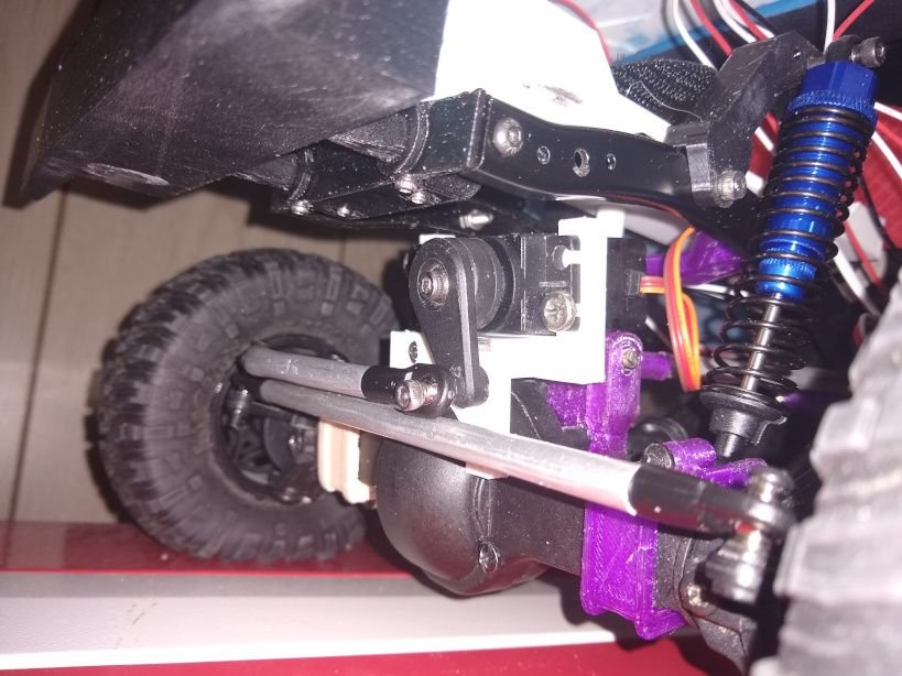
I wanted to go farther back, but the servo horn couldn't be moved back even 1 more millimeter before it wouldn't work anymore it is JUST clearing the mount now, but with the battery mount removed it clears perfectly.
The new battery box which now screws into the front body mount. It also only needs one strap now due to having a front, and back on it so the battery can't slide around.
With these changes the front shocks can now almost bottom out(they have like 1mm left in travel) before the servo hits the strap of the battery tray
In the bottom picture you might notice the LED sticking out of the side turn signal marker location... yea that is all that is left to make for this thing, and it is done. I designed a part, and printed it in white to test fit it, but I need clear filament to make it so it looks right, and works. I plan on ordering a roll soon when I restock on printer supplies.
I did forget to say a few things.
One is I had to rotate the hinges for the hood 90 degrees, and reprint them. I originally printed them flat and one broke on the layer line a few days after I made them so with the rotation in printing it made it stronger.
Also the windshield hinges are actually hinges that can articulate even though the windshield doesn't fold down. I did this as it was easier to design working hinges which I also figured would look better then to get the slight angle right, and print them with it.
All in all so far I'm happy with how it went I do wish I got the roof smoother as you can see some 3d printed layer lines in it, but I pretty much smoothed out where the 2 parts connected in the back. I might eventually get a little softer spring for it as the ones that it has I think are for a buggy or something, and are a little hard for crawling.
Ohh this also has locked diffs. Turns out the rear diff was from a crawler king, and had a diff locker in it, and I made one for the front.
Also when I get more black PLA, and some time I might remake all the visible parts in black to get rid of the random purple pieces, and the white servo mount you can easily see. But I got other things I'm currently working on that are more important. I could also just wait till they break as the clear purple parts kinda seem a bit fragile after the 6 or so years I initially printed them.
Well with it painted, wired up, and having windows I still wasn't happy with some things
Namely I hated how it sat with the stock wheely king shocks
So I ordered a set of 70mm shocks which from what I saw are the same length as scx10 shocks which brought the ride height down a lot(I think the WK were 120mm >.> ), makes it look better, and it also isn't wobbly anymore... The WK shocks the body would sit a bit slanted(there isn't a pic it is something seen in person), but now it is perfectly straight.
But the new shocks introduced a new problem
I had less then 2mm's travel before the steering servo would slam into the bumper mount....
SO I had to redesign the steering servo mount moving the servo around 20mm's farther back, remove the front battery tray mount, and design a completely new battery tray with spacers.
I wanted to go farther back, but the servo horn couldn't be moved back even 1 more millimeter before it wouldn't work anymore it is JUST clearing the mount now, but with the battery mount removed it clears perfectly.
The new battery box which now screws into the front body mount. It also only needs one strap now due to having a front, and back on it so the battery can't slide around.
With these changes the front shocks can now almost bottom out(they have like 1mm left in travel) before the servo hits the strap of the battery tray
In the bottom picture you might notice the LED sticking out of the side turn signal marker location... yea that is all that is left to make for this thing, and it is done. I designed a part, and printed it in white to test fit it, but I need clear filament to make it so it looks right, and works. I plan on ordering a roll soon when I restock on printer supplies.
I did forget to say a few things.
One is I had to rotate the hinges for the hood 90 degrees, and reprint them. I originally printed them flat and one broke on the layer line a few days after I made them so with the rotation in printing it made it stronger.
Also the windshield hinges are actually hinges that can articulate even though the windshield doesn't fold down. I did this as it was easier to design working hinges which I also figured would look better then to get the slight angle right, and print them with it.
All in all so far I'm happy with how it went I do wish I got the roof smoother as you can see some 3d printed layer lines in it, but I pretty much smoothed out where the 2 parts connected in the back. I might eventually get a little softer spring for it as the ones that it has I think are for a buggy or something, and are a little hard for crawling.
Ohh this also has locked diffs. Turns out the rear diff was from a crawler king, and had a diff locker in it, and I made one for the front.
Also when I get more black PLA, and some time I might remake all the visible parts in black to get rid of the random purple pieces, and the white servo mount you can easily see. But I got other things I'm currently working on that are more important. I could also just wait till they break as the clear purple parts kinda seem a bit fragile after the 6 or so years I initially printed them.
Last edited by SyCo_VeNoM; 01-17-2025 at 02:34 PM.
The following users liked this post:
khodges (07-26-2025)
07-24-2025 | 06:35 PM
#10
Thread Starter
didn't see a reply as I had other things going on. The lift isn't as high as it looks as the axles were on a bit of a slant as I took it while sitting on my laser cutter which has like a 10 degree slope. I do wish I could go lower, but if I go any lower it won't really have any articulation so it
Side note it is finished I made the side marker lamps out of clear petg,and I just got to take a picture
Side note it is finished I made the side marker lamps out of clear petg,and I just got to take a picture
01-06-2026 | 03:57 PM
#11
didn't see a reply as I had other things going on. The lift isn't as high as it looks as the axles were on a bit of a slant as I took it while sitting on my laser cutter which has like a 10 degree slope. I do wish I could go lower, but if I go any lower it won't really have any articulation so it
Side note it is finished I made the side marker lamps out of clear petg,and I just got to take a picture
Side note it is finished I made the side marker lamps out of clear petg,and I just got to take a picture
It is possible, Adjusting the length of the links will rotate your axles to the right angle. Just that will lower the shock's mounts on the axle and lower the lift. Shorter shocks will help too. The links parallel to the ground or close will improve performance . And lower center of gravity beats too much flex


