


TopRCModel FW-190
 02-03-2023, 09:18 AM
#1551

I PM Reverend 2 weeks ago and haven't heard back. Not sure he is still making them.
Planenutzz
Or anybody else. Do you know how long the stand offs need to be for the Saito engine if i don't use the metal plates like your doing?
Thanks for any help
Planenutzz
Or anybody else. Do you know how long the stand offs need to be for the Saito engine if i don't use the metal plates like your doing?
Thanks for any help

 02-03-2023, 12:50 PM
#1553
get out a suitable ruler and take measurements measure measure measure. It is not hard to do.
02-03-2023, 12:53 PM
#1554
Rev is in a very demanding job and has stepped back from the hobby to devote more time to family goals, he will still do print jobs from time to time but you need to have some patience and not expect he will stop his life every time somebody wants a part for a toy plane.
slowly, slowly catchee monkey
slowly, slowly catchee monkey
02-03-2023, 02:50 PM
#1556
if you know how to measure then suggest you do so as my set up and others will be very different depending on prop type, clearance etc.
If you actually read my posts you will obtain and work out the measurements without even touching a ruler!
It is all bespoke!
If you actually read my posts you will obtain and work out the measurements without even touching a ruler!
It is all bespoke!
02-05-2023, 12:40 AM
#1557
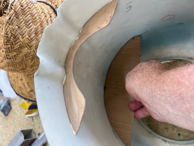
Got a bit of progress over last couple of days. All fiddly stuff to do with the cowl mounting and baffle.
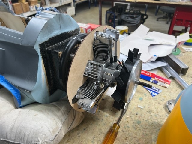
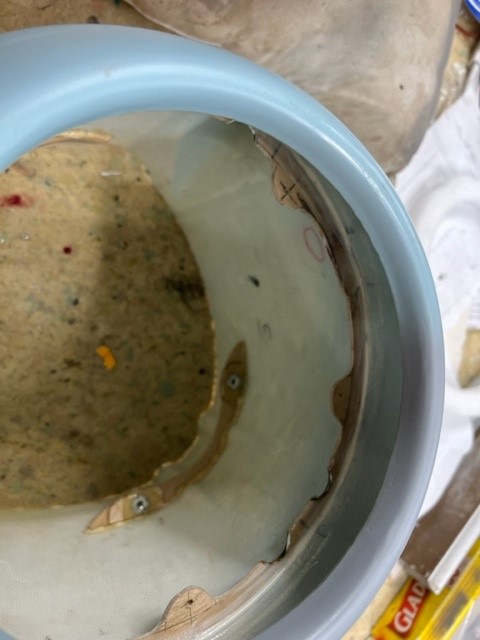
Cowl mounting brackets are glued in with aeropoxy, same as hysol. I may need a couple of thin shims to correct line of the front of the cowl with relation to the fan. It is very close though.
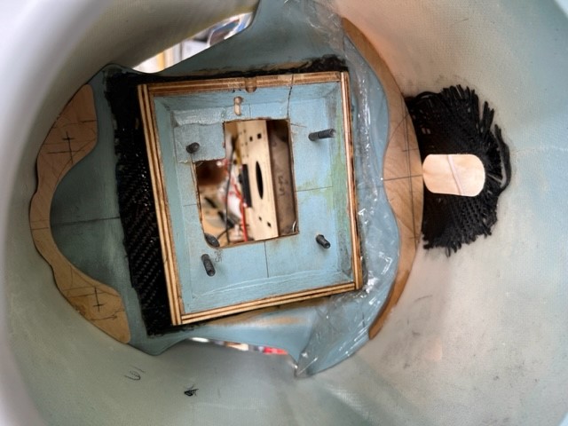
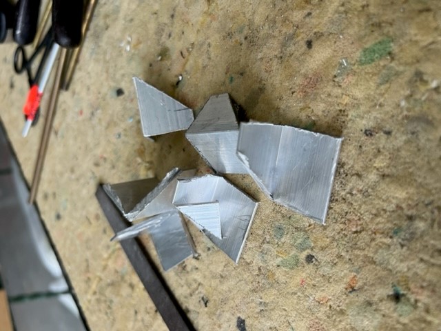
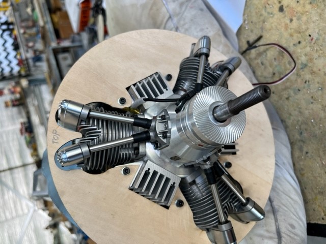
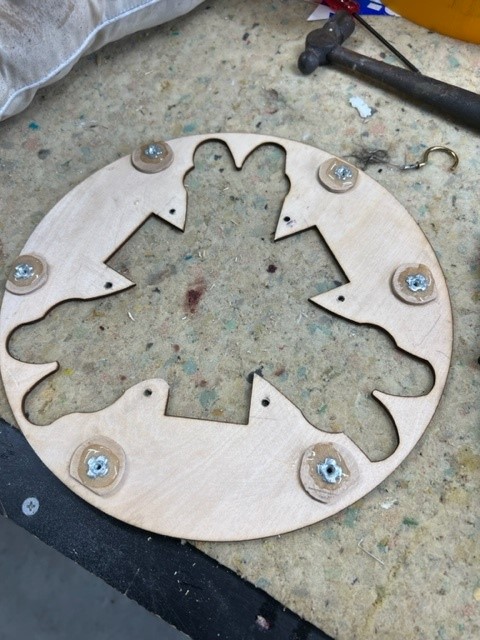
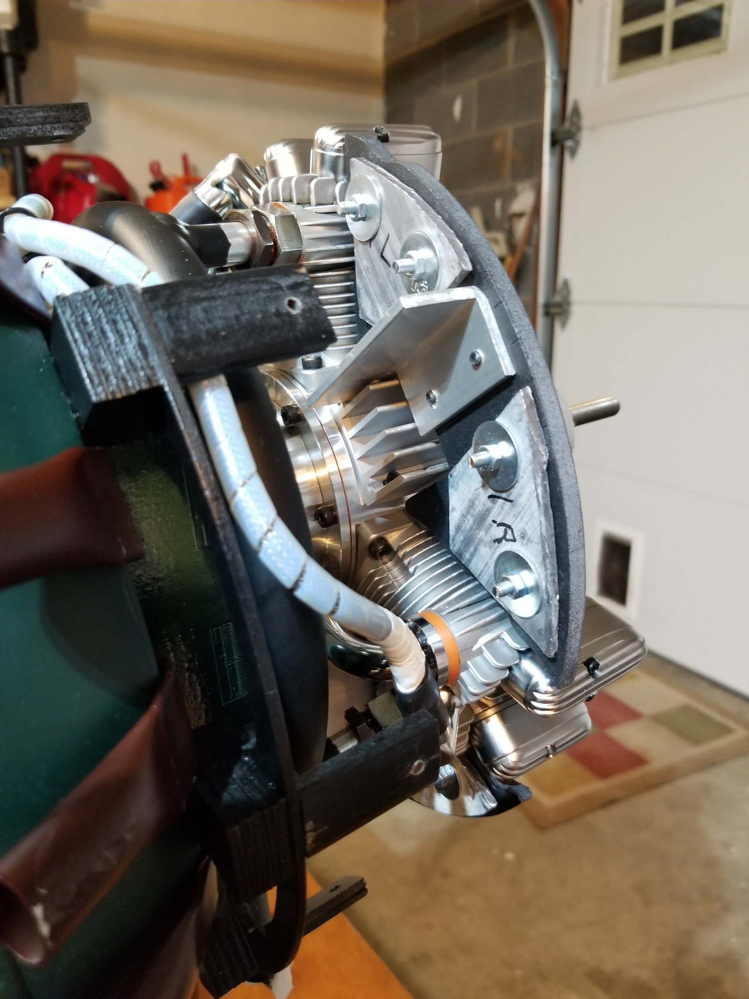
Made up the aluminum brackets that will be screwed to the engine heat sinks and hence the baffle will then be bolted to those.
I will then have a 3mm plywood ring around the inside of the cowl to act as a air seal and for the main baffle to then be screwed to.
Idea is that the cowl can be removed easily and it leaves the main baffle in place bolted to the engine.
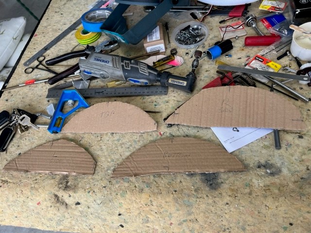
Made up some templates in carboard using contour gauge, they are very close but will need a little trim here and there. Once happy I will then cut the plywood parts.
I will be pleased to have this part behind me as it is all fiddly and slow work.
Hoping my big order of nuts and bolts from RTL arrives tomorrow so I can drill and tap the parts and get this baffle mounting done.
Cowl mounting brackets. Bottom will have 3mm bolts screwed from the front through the main firewall and into captive T-nuts., top will be done in reverse with access from inside the fuz on top of the battery tray.
Had to trim the bottom in the center to allow for exhaust pipe.
Bead of aeropoxy to lock them in place.
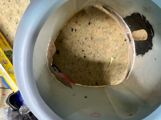
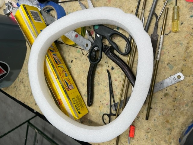
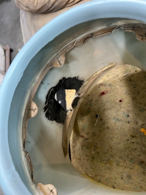
Was going to use the foam piece that was inside the cowl but it is made to suit the rear which is a very different shape to where the baffle will be.
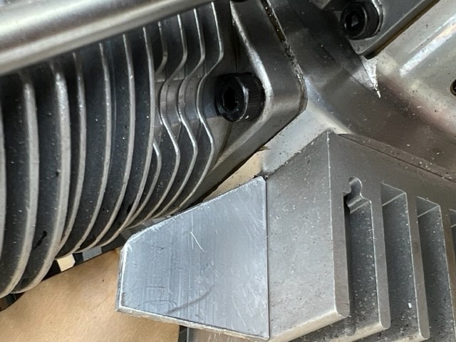
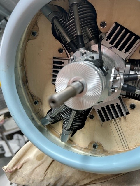
Test fitting, baffle will sit about half way along the heat sinks.
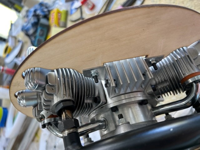
Baffles brackets to go on the heat sinks before they got a bit of filing.
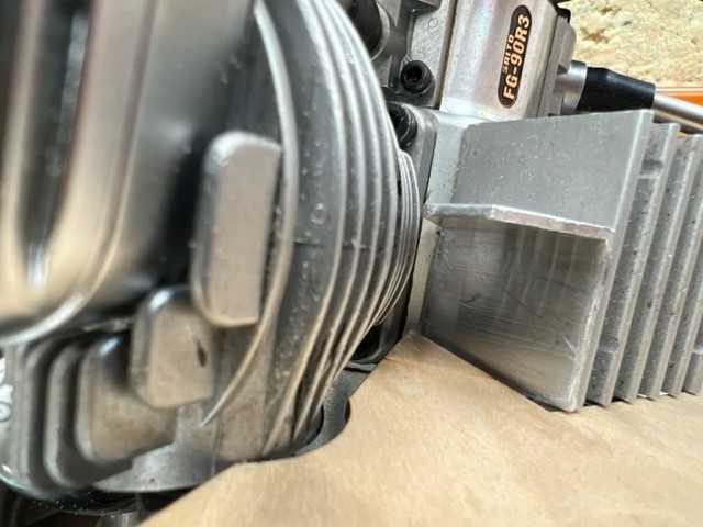
Should work nicely. They will be screwed to the heat sink with 2 bolts and will drill and tap those into the heat sink. One bolt will go through the baffle into the alloy bracket.
Another view.
Cardboard templates for the baffle ring. Not final shape, they will be much narrower, probably about 15mm.
Test fit of the top template. Not bad.
In a while crocodile.
cheers
me
Cowl mounting brackets are glued in with aeropoxy, same as hysol. I may need a couple of thin shims to correct line of the front of the cowl with relation to the fan. It is very close though.
Made up the aluminum brackets that will be screwed to the engine heat sinks and hence the baffle will then be bolted to those.
I will then have a 3mm plywood ring around the inside of the cowl to act as a air seal and for the main baffle to then be screwed to.
Idea is that the cowl can be removed easily and it leaves the main baffle in place bolted to the engine.
Made up some templates in carboard using contour gauge, they are very close but will need a little trim here and there. Once happy I will then cut the plywood parts.
I will be pleased to have this part behind me as it is all fiddly and slow work.
Hoping my big order of nuts and bolts from RTL arrives tomorrow so I can drill and tap the parts and get this baffle mounting done.
Cowl mounting brackets. Bottom will have 3mm bolts screwed from the front through the main firewall and into captive T-nuts., top will be done in reverse with access from inside the fuz on top of the battery tray.
Had to trim the bottom in the center to allow for exhaust pipe.
Bead of aeropoxy to lock them in place.
Was going to use the foam piece that was inside the cowl but it is made to suit the rear which is a very different shape to where the baffle will be.
Test fitting, baffle will sit about half way along the heat sinks.
Baffles brackets to go on the heat sinks before they got a bit of filing.
Should work nicely. They will be screwed to the heat sink with 2 bolts and will drill and tap those into the heat sink. One bolt will go through the baffle into the alloy bracket.
Another view.
Cardboard templates for the baffle ring. Not final shape, they will be much narrower, probably about 15mm.
Test fit of the top template. Not bad.
In a while crocodile.
cheers
me
02-11-2023, 08:21 PM
#1558
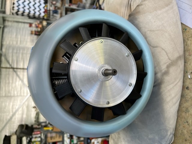
Made some good progress last few days. Cowl mounting system is done, 2 4mm bolts into captive nuts top and bottom. Top ones are accessed via inside the fuz and bottom ones from where the exhaust tube comes out. Works very well and no screws through outside of the cowl.
Baffle is also fitted to the engine, next job is the ring of 3mm plywood that acts as an air seal and the circumference of the baffle with bill screwed to.
Cowl can then be removed and baffle stays on the engine.
Almost broke the back of this one.
Top cowl mounting 4mm bolts
Aluminum plates the baffles are bolted to.
Bottom two cowl mounting 4mm bolts
02-12-2023, 12:33 AM
#1560
thanks GM.
3 segments of the baffle ring is tacked into place. I'll shape the last one tomorrow after work. Drill the mounting holes then secure in place with a bead of aeropoxy (hysol).
Getting there!!

See ya later crocagator!
3 segments of the baffle ring is tacked into place. I'll shape the last one tomorrow after work. Drill the mounting holes then secure in place with a bead of aeropoxy (hysol).
Getting there!!
See ya later crocagator!
02-13-2023, 02:27 PM
#1561
Baffle ring is in and a bead of aeropoxy is securing it. Next I have to somehow mark on the baffle where the holes will go. Have not quite worked out how to do that but will find a way.
Putting those 3mm bolts in will be a bit tricky but should have just enough room for a ball hex driver.
Will look better once painted with firewall black.
Putting those 3mm bolts in will be a bit tricky but should have just enough room for a ball hex driver.
Will look better once painted with firewall black.
02-14-2023, 01:36 PM
#1562
ok finally got the cowl baffle ring done and the baffle bolts to it with 6 x M3 screws. they are quite tricky to get in but doable after I eased the holes quite a bit. Another modeler has suggested not to attach the baffle to both the engine and cowl as it will shake the cowl. I'll run it and see. Others have gone same path I have using the same method and I am sure there would be lots of posts about it if it was an issue.
Now that this big job is done I have think about what I will do next. Can't spray paint due to the humidity so that rules out all flying controls as they all need a bit of a squirt of paint on control horns and inside the flaps.
I might start on a choke system for the FG90R3 that will go across the carby trumpet. The method of inserting and screwing into that tiny hole is not doable, plus it does not choke the engine very effectively at all.
After that a shelf above the fuel tank to mount the powerbox, throttle servo can be done.
Terminations of 3 core cables can be done.
02-16-2023, 01:32 PM
#1563
As the weather is not being kind with humidity I can't do the painting I need to do.
I am starting on a few small jobs one being how to choke the carby via a servo.
On the Saito FG90R3 they give you a rod with an oversized thread on the end that you are supposed to insert and screw into one of the tuning needle holes, then pull to choke the engine. Not only is it a pain in the backside it does not work very effectively at all.
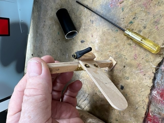
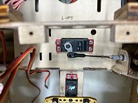
However . . . . placing your thumb over the carby trumpet works very well. Voila I made a mechanical thumb out of a few bits of scrap plywood.
It still needs to have some thickish rubber glued to one side to act as an air seal and to be mounted in such a way to be removable.
Pretty happy with how it is working out and will work well.
I am starting on a few small jobs one being how to choke the carby via a servo.
On the Saito FG90R3 they give you a rod with an oversized thread on the end that you are supposed to insert and screw into one of the tuning needle holes, then pull to choke the engine. Not only is it a pain in the backside it does not work very effectively at all.
However . . . . placing your thumb over the carby trumpet works very well. Voila I made a mechanical thumb out of a few bits of scrap plywood.
It still needs to have some thickish rubber glued to one side to act as an air seal and to be mounted in such a way to be removable.
Pretty happy with how it is working out and will work well.
02-17-2023, 04:06 PM
#1564
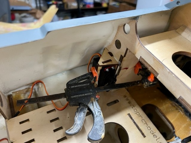
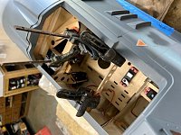
Servos for the choke and throttle are in, linkage on choke done though may need to tweak that yet. The 8mm steel plate the engine is mounted to may yet need to be removed depending on how the CG comes out. At this stage I am expecting I have to remove it. Not a problem as I have 4 8mm standoffs I will substitute if it does get realised.
I'll start making the deck that power box will mount to next. That has to be easily removable so I can access the giblets underneath.
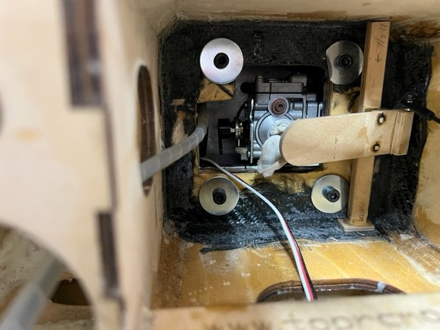
Choke servo
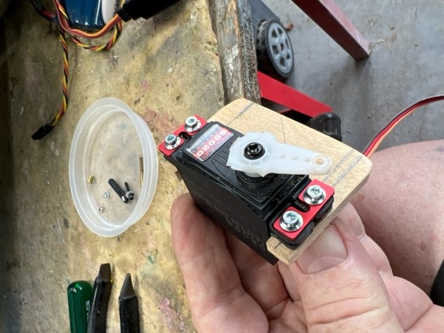
Choke and servo setup
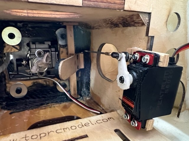
Throttle servo
Later lurkers
I'll start making the deck that power box will mount to next. That has to be easily removable so I can access the giblets underneath.
Choke servo
Choke and servo setup
Throttle servo
Later lurkers
 02-18-2023, 10:02 PM
#1566
I start mine with a Sullivan cone on a 18V drill. Flip it a few times with the ignition off then starts easily every time.
02-19-2023, 03:38 PM
#1567
Got some big shed hrs in last few days and made more progress.
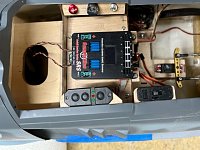
Shelf for the powerbox is in, switches, fuel dot and air filler and gauge.
Shelf of course is removable so I can access fuel tank etc underneath.
I'll do air valve linkage next and terminate elevator leads at the rear.
Support for the shelf
Powerbox SRS Cockpit & switch in

Ignition switch, fuel dot, air gauge & air fill port in.
Later lurkers
Shelf for the powerbox is in, switches, fuel dot and air filler and gauge.
Shelf of course is removable so I can access fuel tank etc underneath.
I'll do air valve linkage next and terminate elevator leads at the rear.
Support for the shelf
Powerbox SRS Cockpit & switch in
Ignition switch, fuel dot, air gauge & air fill port in.
Later lurkers
02-25-2023, 10:38 PM
#1568
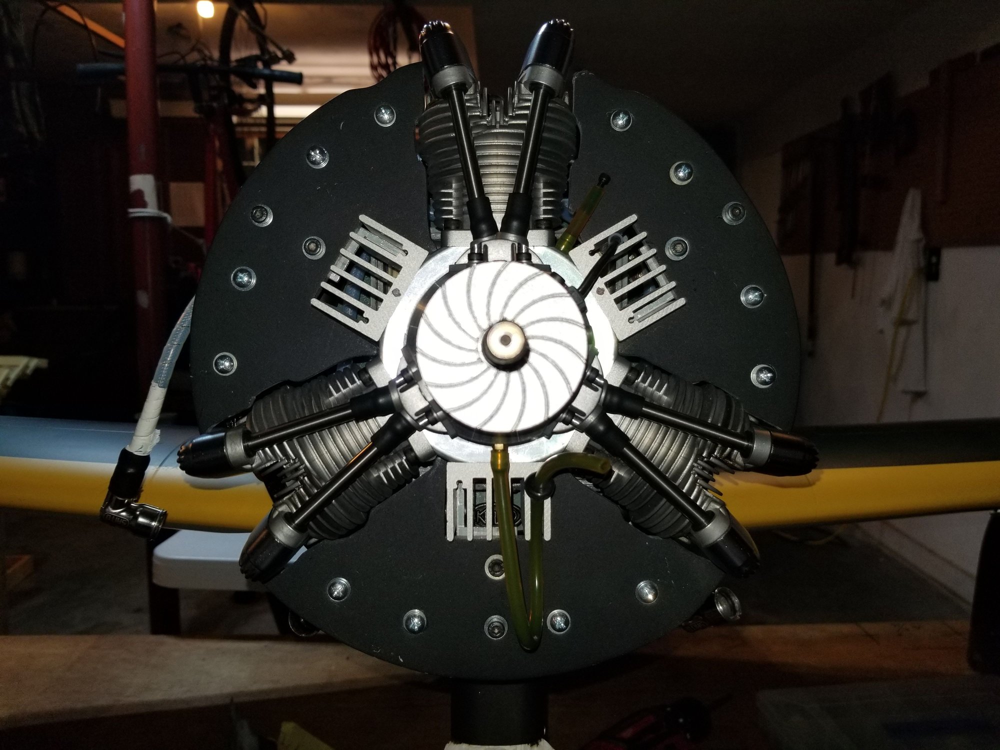
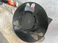
Not a lot of progress but have primed and sprayed satin black the baffle and fittings within the cowl.
Started on the firewall and engine mount as well. Only primed so far as I ran out of rattle can of the black.

Started on the firewall and engine mount as well. Only primed so far as I ran out of rattle can of the black.
02-26-2023, 07:05 AM
#1569
Hey Planenutzz, Love the tight fit of your baffle. I'll be curious how the cowl vibration is affected by attaching to engine as well.
The enclosed cowl on the FW 190 was a problem on the Full Scale. Same on RC model.
Ray English, the Saito Guru, suggests setting the baffle 1 inch back from the front of the heat sink. Basically, centered on engine. This how I did mine.
BUT the big difference in my engine temps is the Fan when comparing to my fan-less Saito 84 in a TopRC Zero. Hopefully, The Reverend is still making them.
I'm guessing 20 degrees cooler...with good baffles. I'm running full speed temps around 210F and cruising around 190F.
On a cg note. I put my nose weight all the way forward under the cowl lip using a vinyl tube filled with lead shot. I did beef up the cowl attachment points to handle the extra weight. I read the pros and cons. So far no problems.

 02-26-2023, 12:38 PM
#1572
Others have gone same method I am using and have not seen a single post say it was an issue. Ground running indicates the engine is very smooth and as it is bolted to an 8mm steel plate that will soak up a lot of any vibration that does present.
I'll ignore nose weight till I get the thing full together and will then see what it needs. I normally use large round fishing sinkers held in with silicon sealant around the lip of the cowl. They sit in nicely but can be difficult to remove.
Slowly, slowly catchee monkey.
I'll ignore nose weight till I get the thing full together and will then see what it needs. I normally use large round fishing sinkers held in with silicon sealant around the lip of the cowl. They sit in nicely but can be difficult to remove.
Slowly, slowly catchee monkey.
02-27-2023, 11:17 PM
#1573
Squirted the baffle and firewall, engine mount box and the bits with a rattle can of firewall paint in a satin black. Phots look like a charcoal gray but it is black.
Not in the mood to do anything this evening after a c rap day at work


Not in the mood to do anything this evening after a c rap day at work
02-28-2023, 12:27 AM
#1574
I positioned the pilot to get relative seating height and then a bit lower for the floor as per this first photo showing that line on outside of fuselage.
I then measured at rear of seat position and at where canopy ends and adding a little for behind the seat I get 120mm
Now I’m guessing the floor will extend say 80mm from where the canopy ends towards the front of plane.
I measure inside at rear of seat and at end of canopy to get basic dimensions though floor will extend that extra 80mm following same outside taper if that makes sense??
The 245mm is a cross at the 120mm length mark.
The sideways measurements are fuselage wall to fuselage wall. Not sure how wide the floor goes on full size.
Need to measure width of the side panels and the seat, both of which are 1/5th scale, not 1/4.5
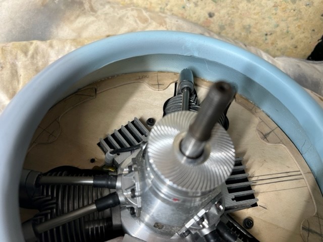
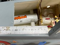
Spindle out travel

Spindle in travel, not a lot of servo arm movement required.
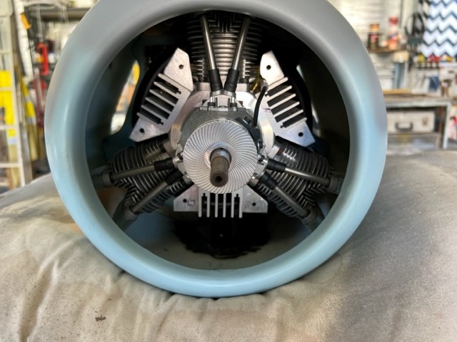
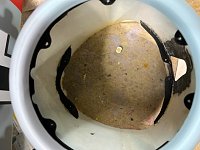
Cowl painted inside up to where the baffle will be

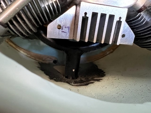
Mounting plates also painted
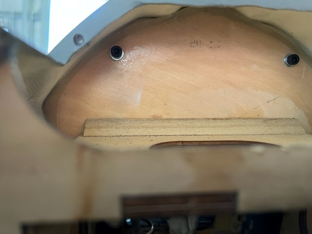
Approx where the floor will be, I measured about 5mm above the tail wheel cables

Rear of seat to the end of the canopy measurement, floor extend rearwards a bit and forward about 80mm
Rough dimensions, fuselage side to fuselage side.

I then measured at rear of seat position and at where canopy ends and adding a little for behind the seat I get 120mm
Now I’m guessing the floor will extend say 80mm from where the canopy ends towards the front of plane.
I measure inside at rear of seat and at end of canopy to get basic dimensions though floor will extend that extra 80mm following same outside taper if that makes sense??
The 245mm is a cross at the 120mm length mark.
The sideways measurements are fuselage wall to fuselage wall. Not sure how wide the floor goes on full size.
Need to measure width of the side panels and the seat, both of which are 1/5th scale, not 1/4.5
Spindle out travel
Spindle in travel, not a lot of servo arm movement required.
Cowl painted inside up to where the baffle will be
Mounting plates also painted
Approx where the floor will be, I measured about 5mm above the tail wheel cables
Rear of seat to the end of the canopy measurement, floor extend rearwards a bit and forward about 80mm
Rough dimensions, fuselage side to fuselage side.