


Super Sporster 40 sort of
 03-09-2020, 03:49 PM
#51


Donated some of my time today to my engine test stand. I am happy with the way it is developing
Test Stand Photos Click Here
.
Test Stand Photos Click Here
.
Last edited by Lee Taylor; 03-09-2020 at 03:51 PM.

The following users liked this post:
jnayjaso (04-05-2020)
03-09-2020, 06:42 PM
#52
Thread Starter

I had a busy day with errands and house work. But in between things and after I made progress on the S.S.
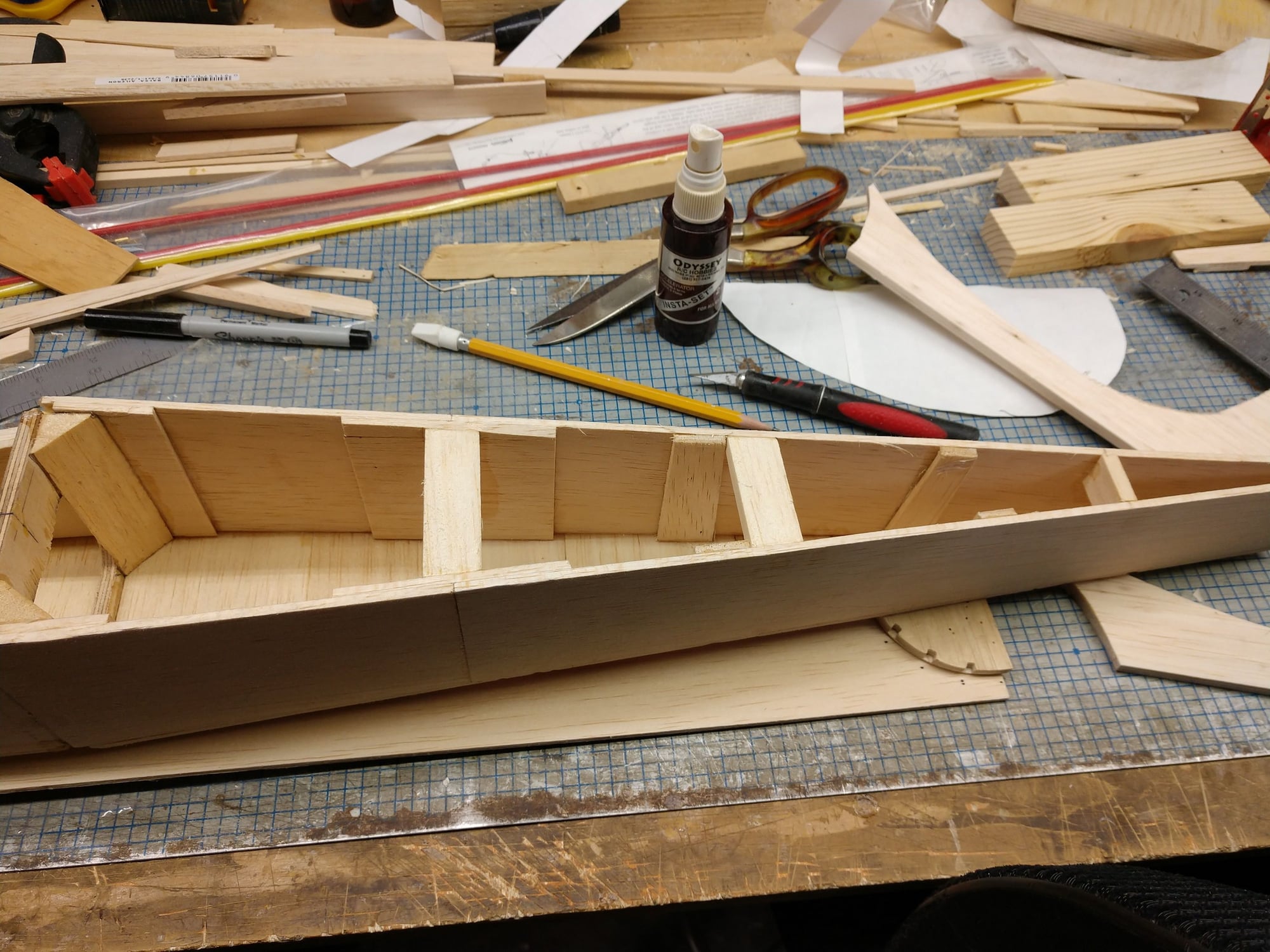
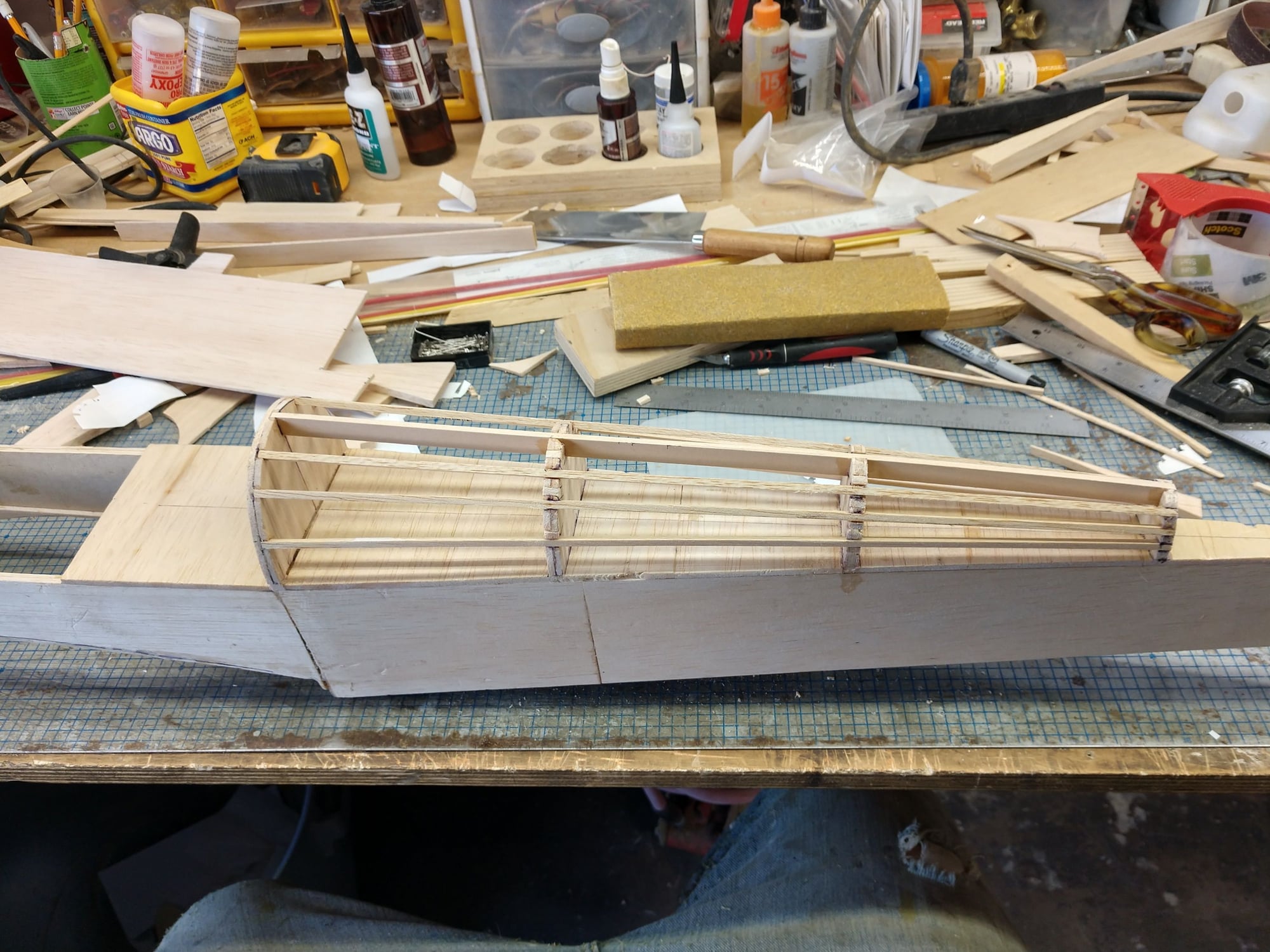
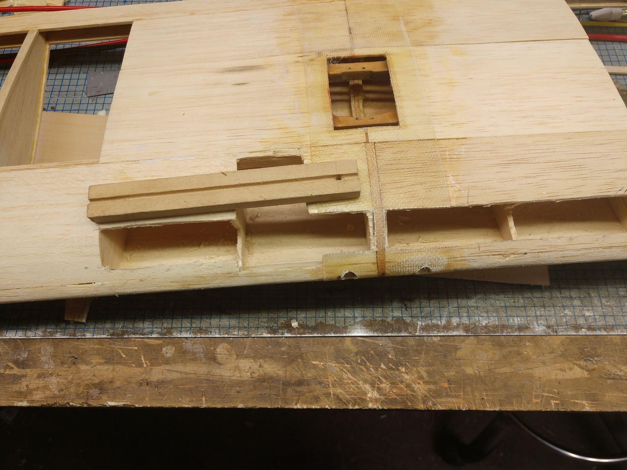
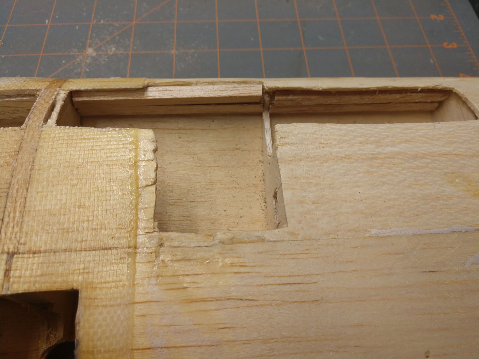
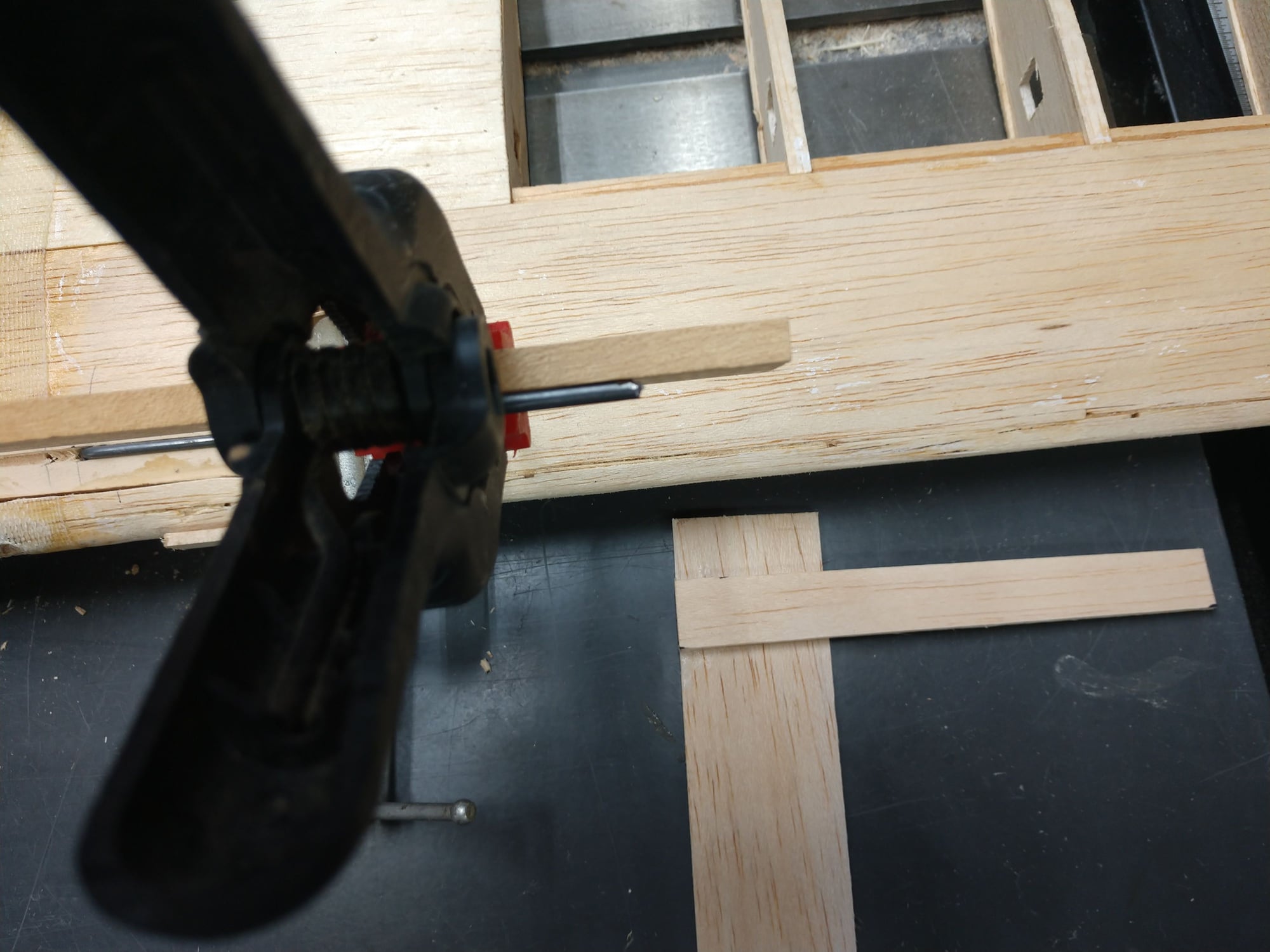
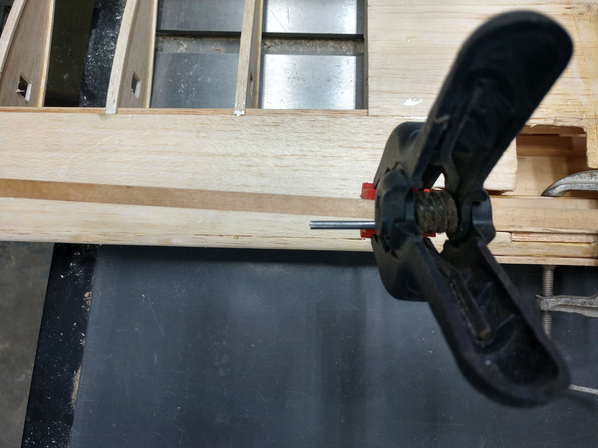
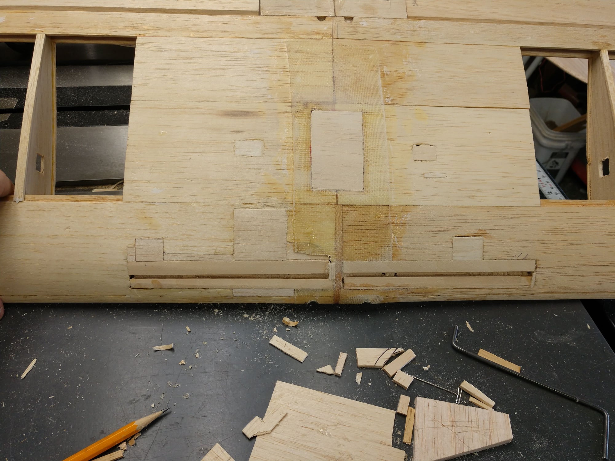
I added some internal bracing, not bulkheads, but same purpose and effect. I added some vertical grain 1/8" sheet strips about 1/2" wide. Iv'e done this with fuse sides that were only 1/16" sheet adding 1/16" sheet vertical strips. Works fine and the fuse sides feel nice and stiff to the fingers, no danger of cracking. And it is so darn easy for a box construction fuse.
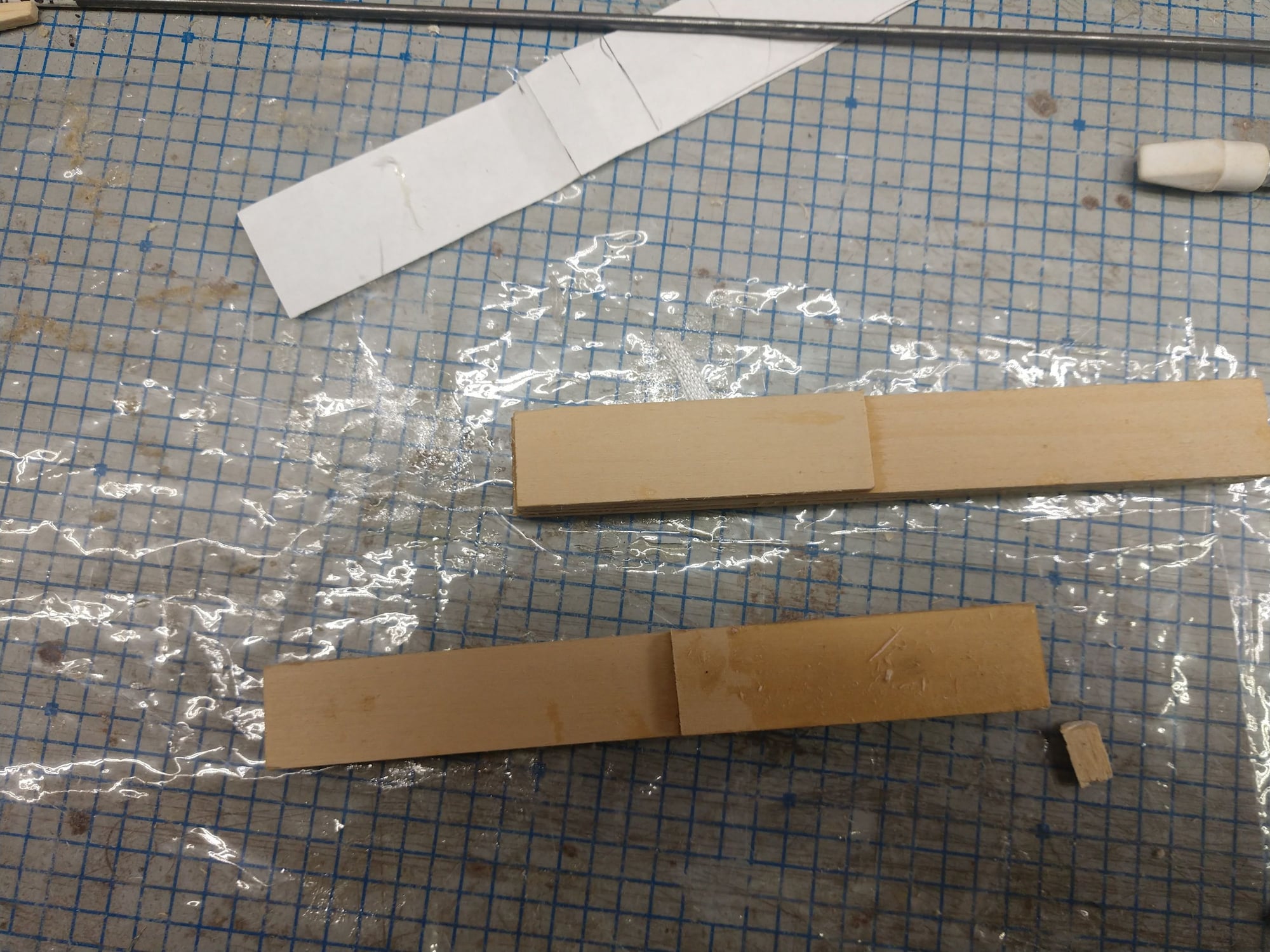
The wide strips inside behind the joiner for the rear fuse section (at the first cross brace is some 1/8" horizontal grain balsa), is a doubler for two separate fuse sheets. I cheaped out. I joined 2 1/8" pieces of sheet to make them long enough instead of cutting 2 new sheets. Plenty strong, 1.5" overlap both sheets.
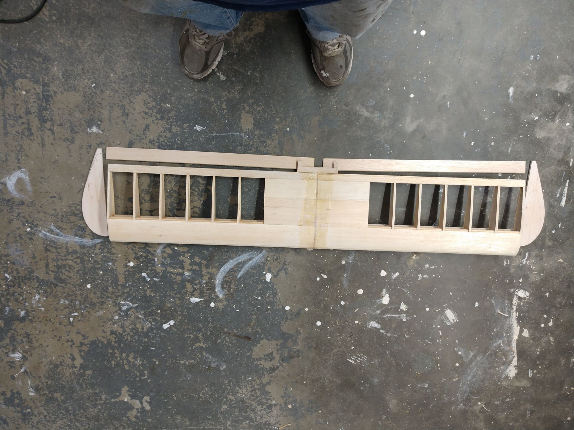
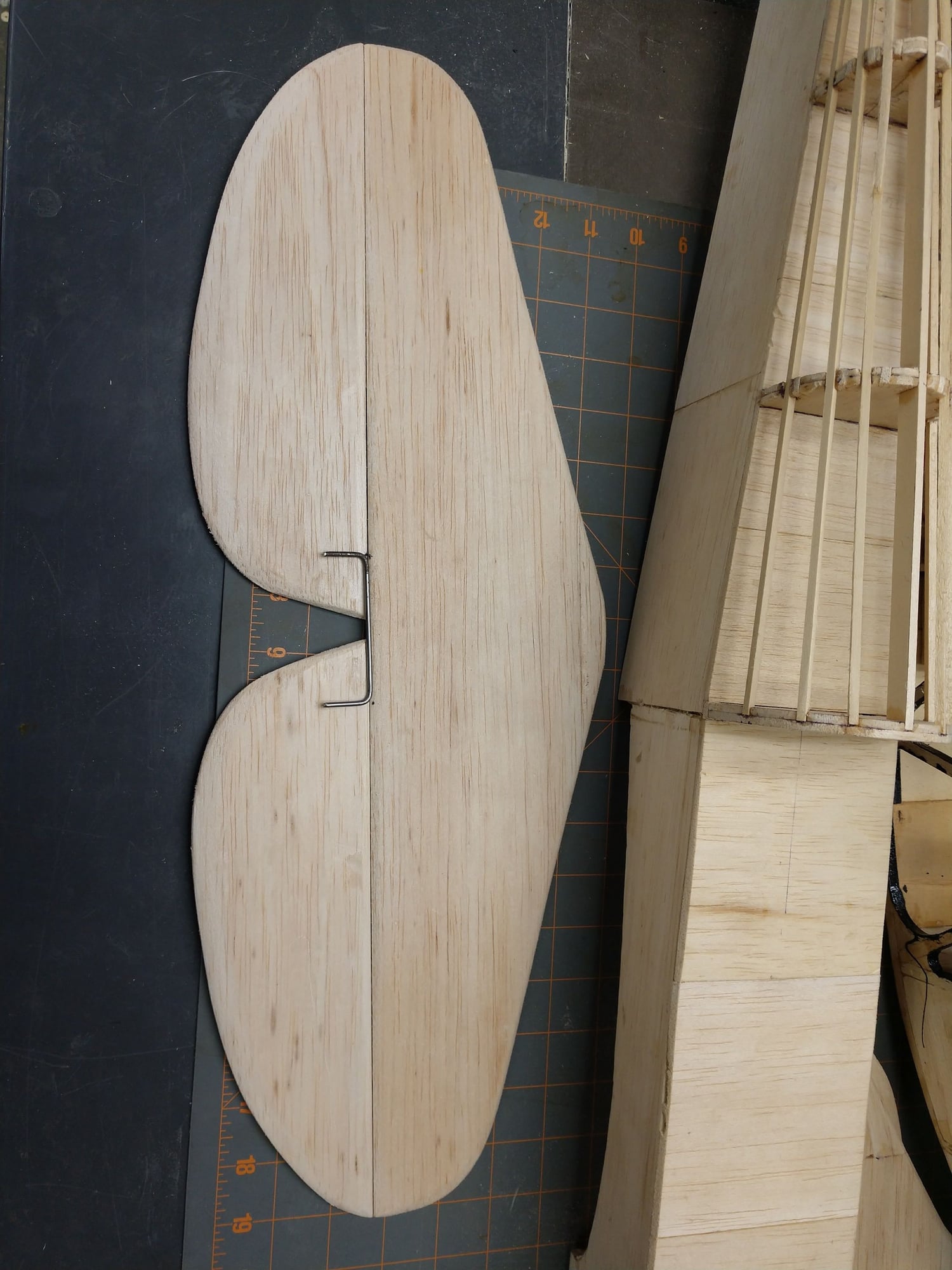
I also made tail feathers. 2 sheets of 1/4". I looked at the price tag after I started cutting them. $6, ouch! The 2 sheets made the stab, 2 elevator half's, both wing tips, and the rudder. I had small pieces left and no more 1/4" sheet stock, so I pieced 3 smaller pieces together to make a piece big enough to make the vertical fin. Will be just fine with some sanding that will be required any way.
And that is a rap for today.
Ken
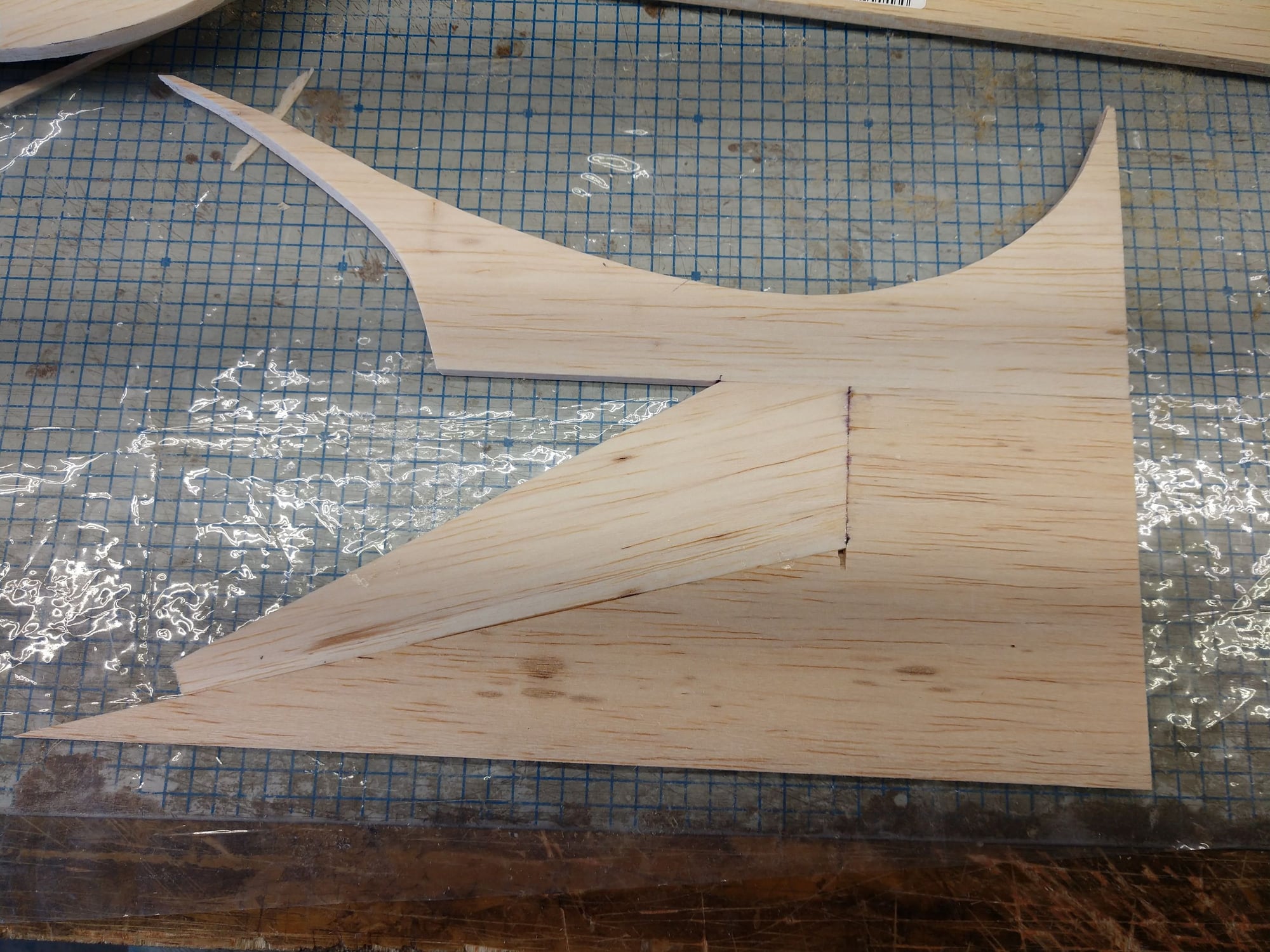
3 small pieces makes a whole vertical fin

See, a whole vertical fin the cheap way
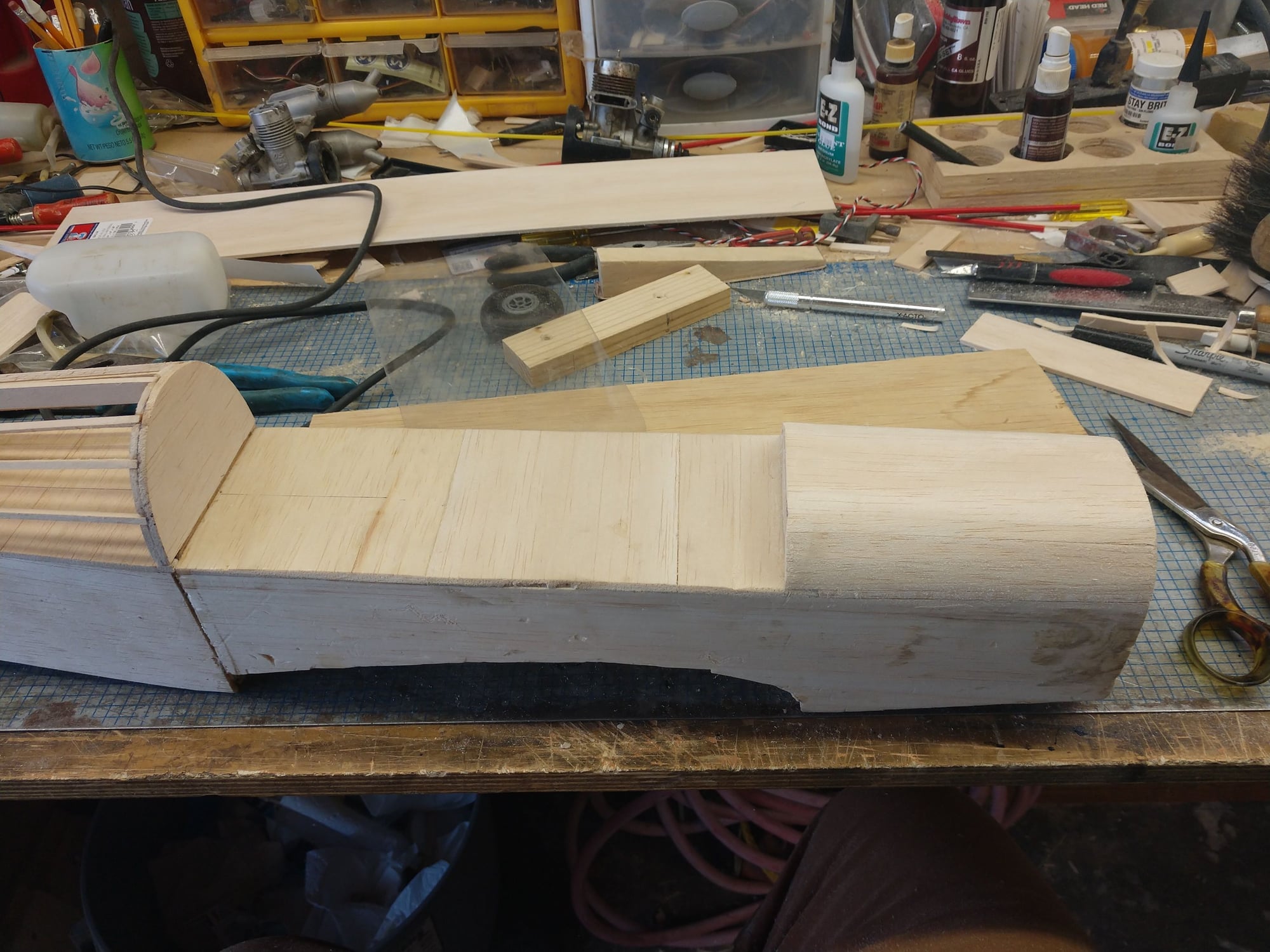
How I jigged the front fuse and the new rear section

I'm going to have to make some new formers. I forgot that I made the fuse wider so the 10 oz fuel tank would fit between former #2's sides
I added some internal bracing, not bulkheads, but same purpose and effect. I added some vertical grain 1/8" sheet strips about 1/2" wide. Iv'e done this with fuse sides that were only 1/16" sheet adding 1/16" sheet vertical strips. Works fine and the fuse sides feel nice and stiff to the fingers, no danger of cracking. And it is so darn easy for a box construction fuse.
The wide strips inside behind the joiner for the rear fuse section (at the first cross brace is some 1/8" horizontal grain balsa), is a doubler for two separate fuse sheets. I cheaped out. I joined 2 1/8" pieces of sheet to make them long enough instead of cutting 2 new sheets. Plenty strong, 1.5" overlap both sheets.
I also made tail feathers. 2 sheets of 1/4". I looked at the price tag after I started cutting them. $6, ouch! The 2 sheets made the stab, 2 elevator half's, both wing tips, and the rudder. I had small pieces left and no more 1/4" sheet stock, so I pieced 3 smaller pieces together to make a piece big enough to make the vertical fin. Will be just fine with some sanding that will be required any way.
And that is a rap for today.
Ken
3 small pieces makes a whole vertical fin
See, a whole vertical fin the cheap way
How I jigged the front fuse and the new rear section
I'm going to have to make some new formers. I forgot that I made the fuse wider so the 10 oz fuel tank would fit between former #2's sides
The following users liked this post:
jnayjaso (04-05-2020)
The following users liked this post:
jnayjaso (04-05-2020)
03-10-2020, 07:58 AM
#54
Thread Starter
I have used both plastic hinges and the super glue hinges.
On a .25 sized plane I don't pin, but any thing bigger will get 1 or even 2 tooth pick pins.
I am thinking I will use Robart hinges on this plane. I have future project that needs Robart style hinges (a 60cc 1/3 scale Pitts, plans build) for scale effect. Iv'e never used them so it is time to learn.
On the plastic hinges I like to remove the pins, and then replace with a real small diameter the length of piano wire the length of the control surface. That makes the control surface easy to remove if needed. Those planes have always been bigger than a .25. And they also tend to get 2 tooth pick pins each half.
Ken
The following users liked this post:
jnayjaso (04-05-2020)
03-10-2020, 05:07 PM
#55
Thread Starter
I only have one pic today, even though I was busy all day.
Had hospice out for mom, long visit.
Replace the primer bulb in the weed wacker. The first start took a while. I ended up giving it a prime of model airplane fuel. Still did not start. I found the kill switch was stuck closed. So wed wacking followed.
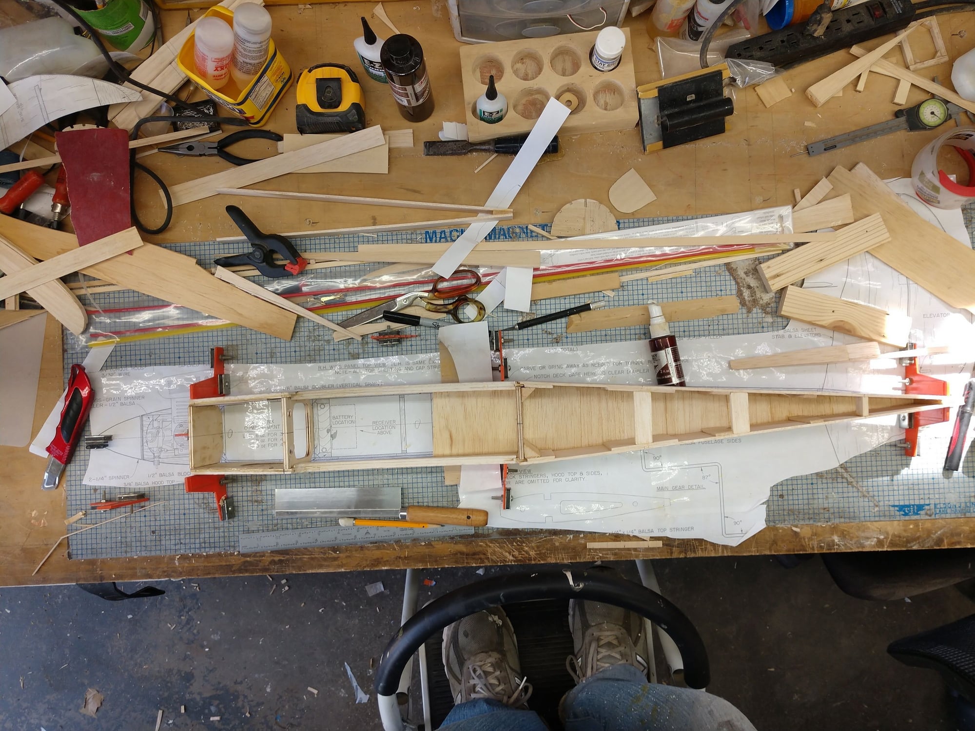
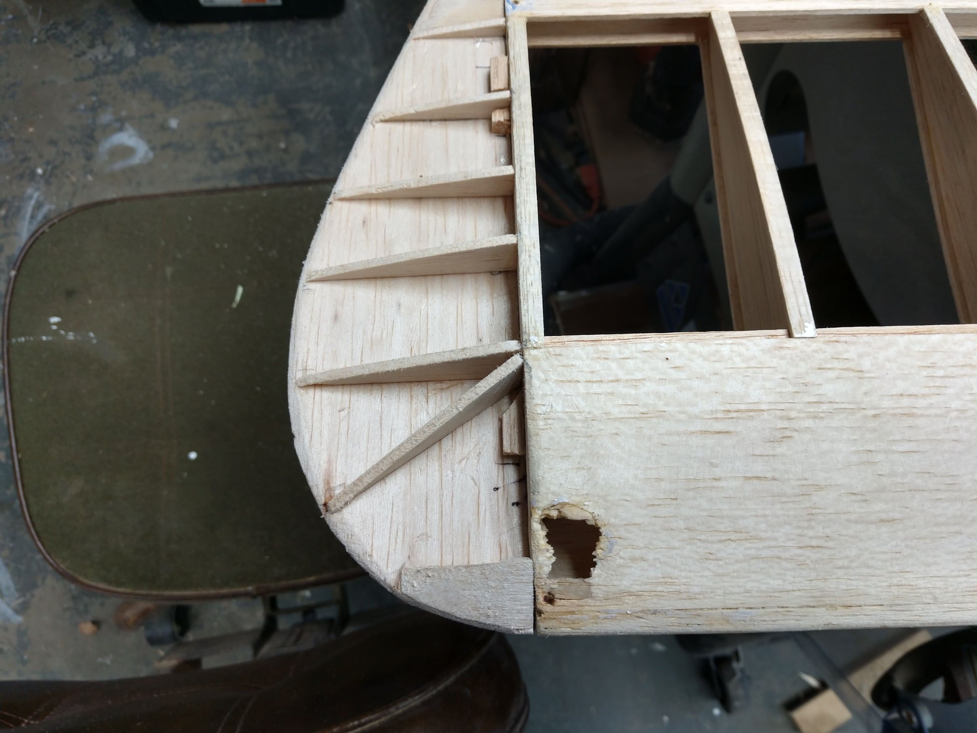
I had to make all new formers as I had made the fuse a little wider. I found the trick was to make the front one at the back of the cockpit and the last one in front of the stab. Then hen by laying the top stringer in I got the correct height of the middle 2. And the same method also gave me the sides roughly of the middle 2 formers. A long block sander then finished them to proper size. Sort of the same technique to get the correct spacing for the rest of the stringers. It was a fairly long process.
Ken
Had hospice out for mom, long visit.
Replace the primer bulb in the weed wacker. The first start took a while. I ended up giving it a prime of model airplane fuel. Still did not start. I found the kill switch was stuck closed. So wed wacking followed.
I had to make all new formers as I had made the fuse a little wider. I found the trick was to make the front one at the back of the cockpit and the last one in front of the stab. Then hen by laying the top stringer in I got the correct height of the middle 2. And the same method also gave me the sides roughly of the middle 2 formers. A long block sander then finished them to proper size. Sort of the same technique to get the correct spacing for the rest of the stringers. It was a fairly long process.
Ken
The following users liked this post:
jnayjaso (04-05-2020)
03-10-2020, 05:10 PM
#56
Thread Starter
One other note The top stringer is Bass, the others Balsa. The seem a little soft and feel like they could break fairly easily. I may try and sneak a doubler in behind them. Will have to be in sections between the formers.
Ken
Ken
The following users liked this post:
jnayjaso (04-05-2020)
03-11-2020, 08:02 PM
#57
Thread Starter
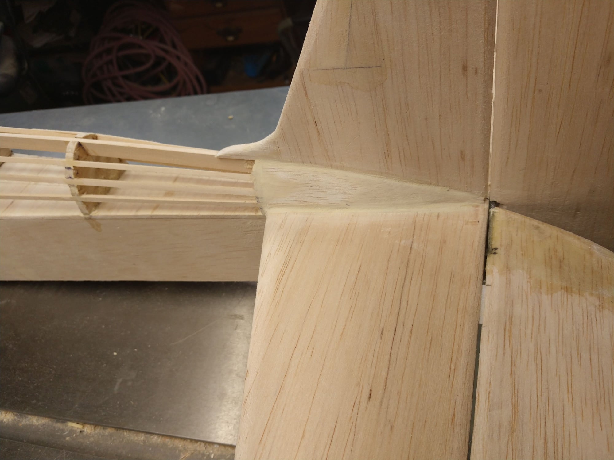
I spent my airplane time replacing the Balsa stringers with Bass stringers. Way in the heck better. I think it only added grams extra. Don't have a scale.
It was actually easy to get the Balsa stringers out. I did not even break one of them.
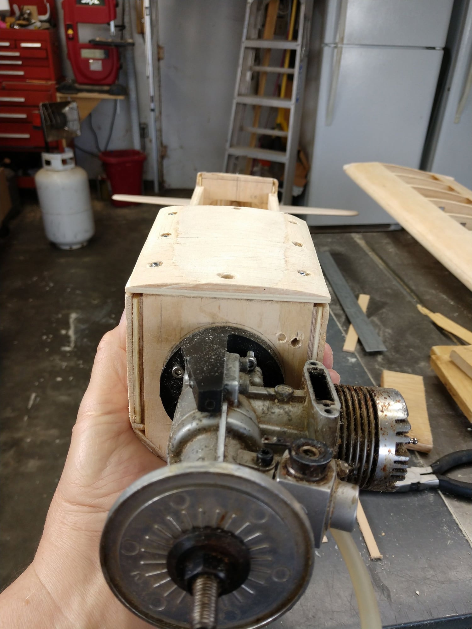
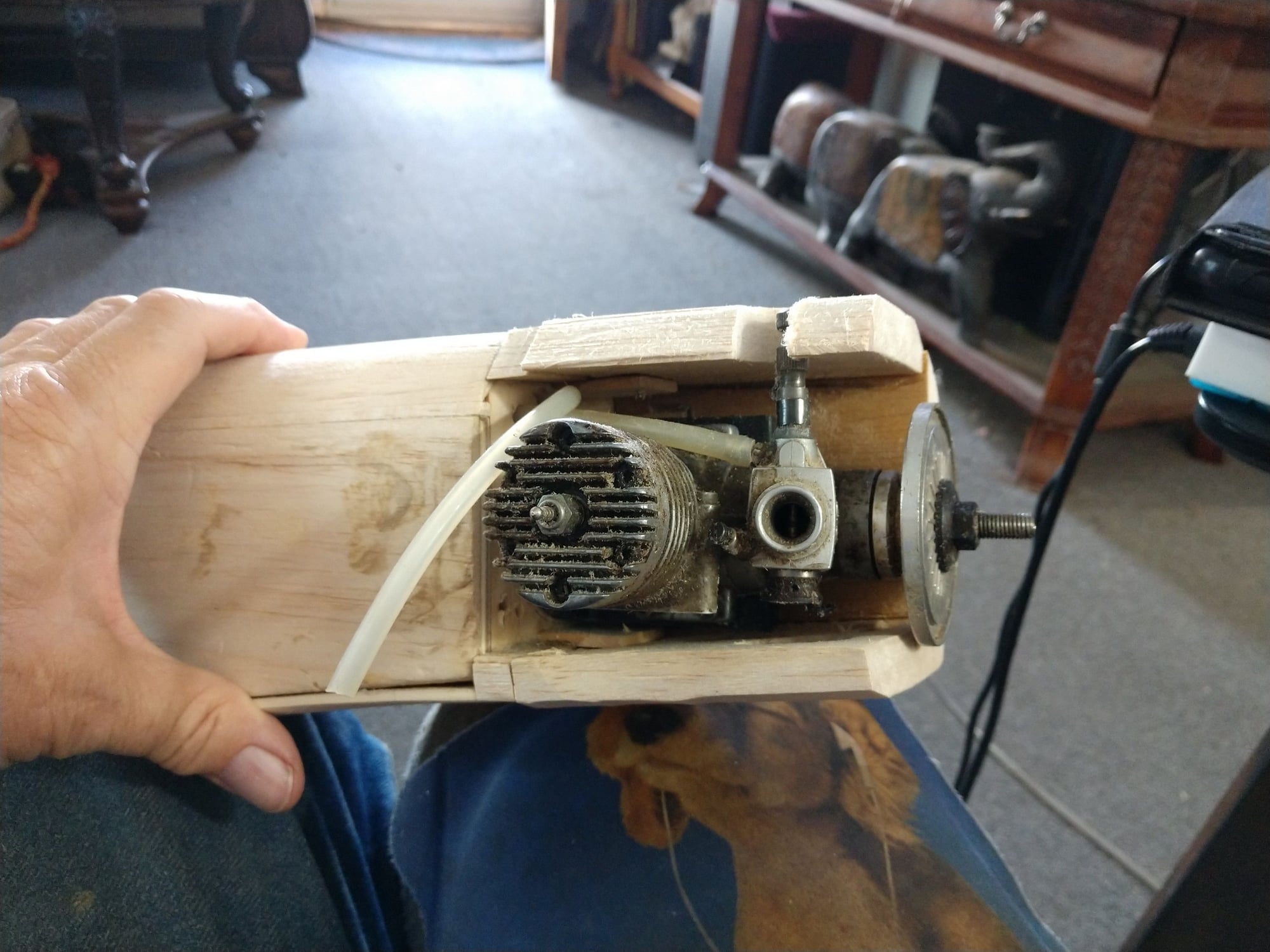
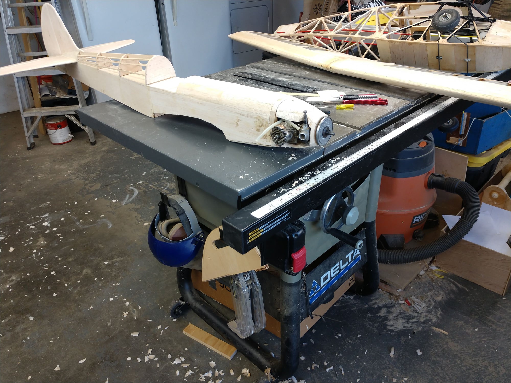
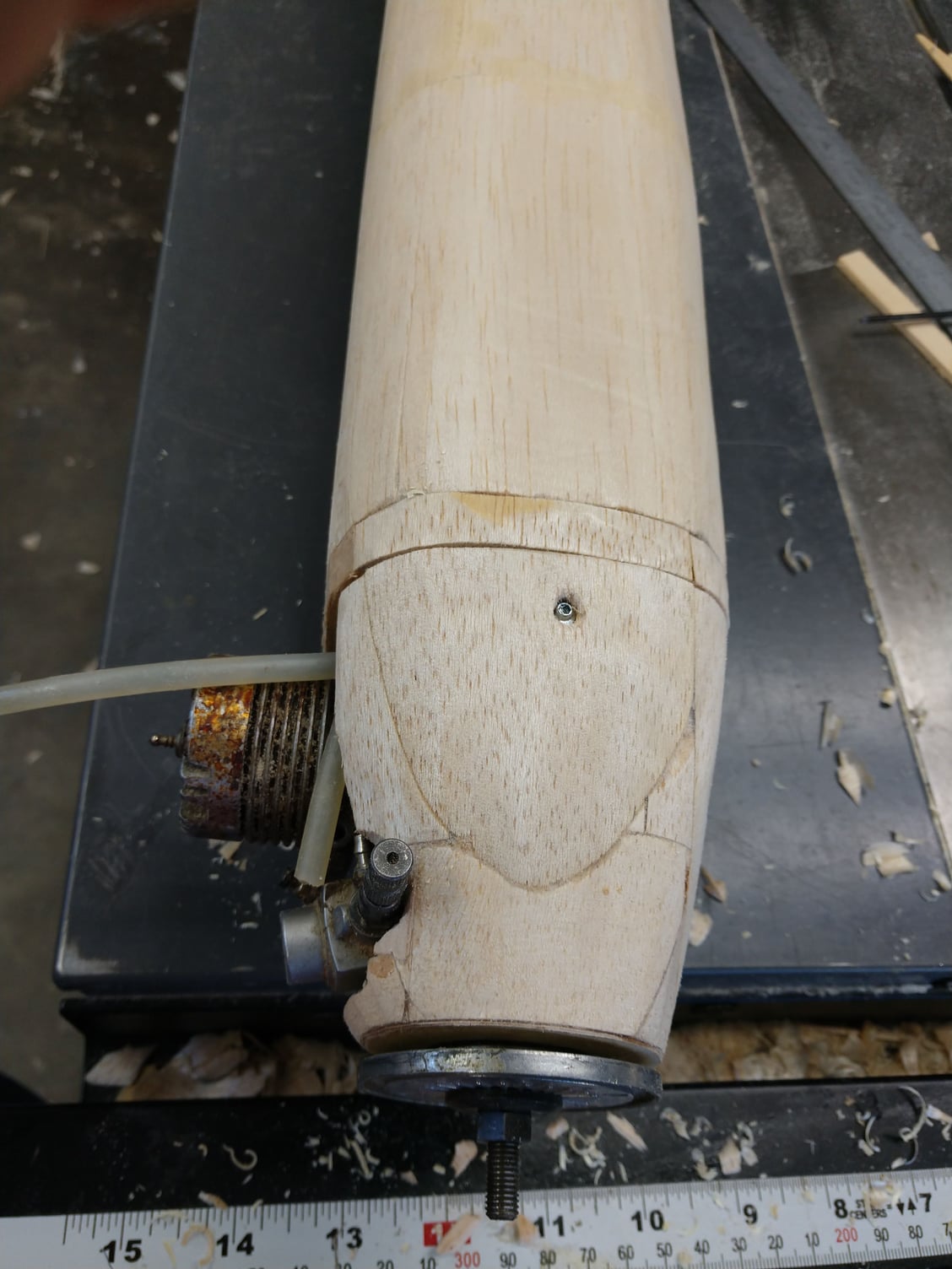
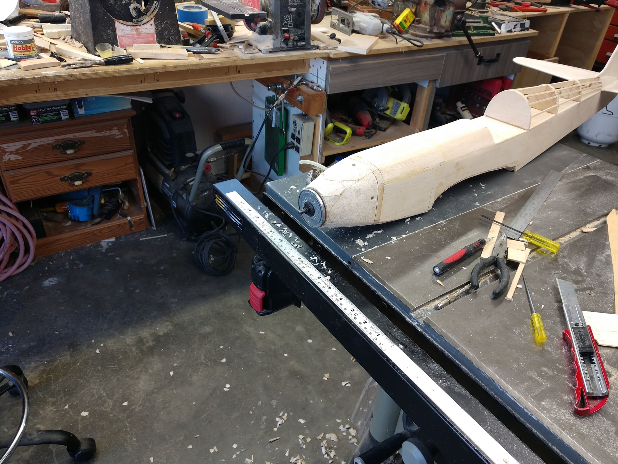
I also mounted the engine mount. This is going to be a side winder installation, engine on it's side. I did this to get the engine carb and the fuel tank to line up. If I had stretched the tank compartment 1/2" I might have been able to get the tank up high enough, but i didn't think of it. The back of the tank protrudes thru former #2.
But I also got a few minutes on my Pacific Ace 74 today, painting frame work that the windshield and windows will leave exposed.
Ken
It was actually easy to get the Balsa stringers out. I did not even break one of them.
I also mounted the engine mount. This is going to be a side winder installation, engine on it's side. I did this to get the engine carb and the fuel tank to line up. If I had stretched the tank compartment 1/2" I might have been able to get the tank up high enough, but i didn't think of it. The back of the tank protrudes thru former #2.
But I also got a few minutes on my Pacific Ace 74 today, painting frame work that the windshield and windows will leave exposed.
Ken
The following users liked this post:
jnayjaso (04-05-2020)
The following users liked this post:
jnayjaso (04-05-2020)
03-13-2020, 06:32 PM
#59
Thread Starter
Never did slot cars. I'm not sure where I get the term from.
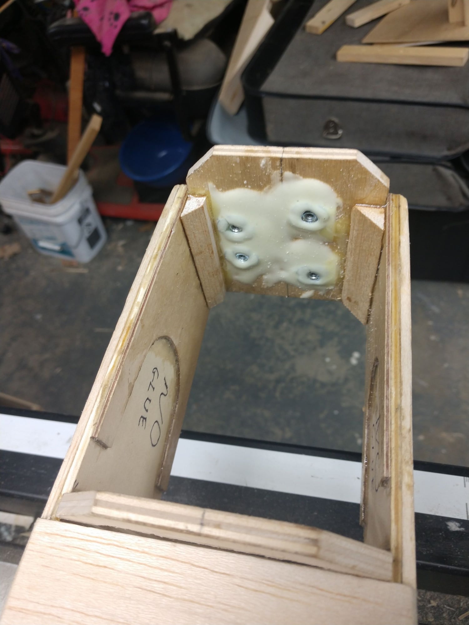
Busy day but I did snag a bit of time to work on the S.S. One of the T nuts in the fire wall was not staying very well. Well now they are all epoxied in. And Iv'e partially spread a thin film of epoxy around the tank compartment. Will do the rest later.
To add I also sanded the tail surfaces, Rounded the front, and tapered the trailing edges. I made sure to blunt somewhat the trailing edges. Sharp trailing edges on control surfaces are more apt to cause flutter. Been there twice. Scary stuff. Lesson learned.
Ken
The following users liked this post:
jnayjaso (04-05-2020)
03-14-2020, 06:29 PM
#60
Thread Starter
No actual construction today other than the torque rod for the elevators.
I spent the day fooling around with making a piano wire bender.
I have always bent the wire with pliers, a vise, and a hammer to persuade the wire to my will with varying degrees of success.
I am going to have to bend some landing gear struts up at some point here. I have a couple of struts like the S.S uses, but they are way to short. I just checked the plans and it does not call out the wire size. Any know? I assume 1/8", really for no good reason.
I use 2 pieces of 3/4" ply glued together, because that is what I had on hand. I first tried a piece of 1" by 2" as my bending handle and some stainless steel screws. It had no trouble bending small the small Wire used for the torque rod, but I ended up with a twist.The screw heads prevented the wire stay flat on the base.
Next try I hunted for some steel bars I remembered that I had stashed some wheres. Hunted and just as I gave up hope of finding them, I glanced to my side and low and behold spotted them.
The 1.5" ply base was drilled and tapped for 1/ - 20 bolts for the backing bar and the pivot bolt.
I drilled a 1/4" hole for my pivot pin and a 13/64" near it to tap for a 1/4 - 20 bolt. Wrong geometry. Tried the other end and the spacing was off. So it was way, way easier to just use the bar than cut off the end and try it again. Took more care and laid the handle in the correct location and moved in the way I expected things to work. Marked the locations and LABELED what each hole was so I would drill the correct size holes in the correct location. I also took more time tapping the 1/4 - 20 hole.
To hold the wire in place I just screwed a piece of 1 by 2 on top of the wire and against the backing bar.
Success on the first try. The wire was dead on flat and Was the length between bends that I had marked.
I was a bit jazzed so decided to go for broke. 3/16" wire. I only did one bend as the pivot hole in the base stripped out. Ply is just to soft. Mable might work and I do have some. I did not clamp the bender down and on the 3/16" it was difficult to hold, but I still managed a 90 degree bend. My mark ended up at the end of the bend, not the middle. Maybe a better clamping system? 3/16" wire is the size used for the 1/3 scale Pitts Special I am going to build, so I now know I can bend the gear with a sturdier wire bender.
So I need a much better base. I'm thinking the wasted steel bar mounted to the ply base might work and I won't have to buy anything.
There is a thread that I got my ideas from. There are 3 PDFs.
Ken

The backing bar (left) has slots cut in it so it can be adjusted for different sizes of wire. The bolt closest to the bottom of the pic is the pivot pin. The wire bends around it. The bolt just above and right is the bolt that actually bends the wire It has to go below the top of the base so I used a Fostner drill bit and wood chisel to re-leave a slot for it in the base.
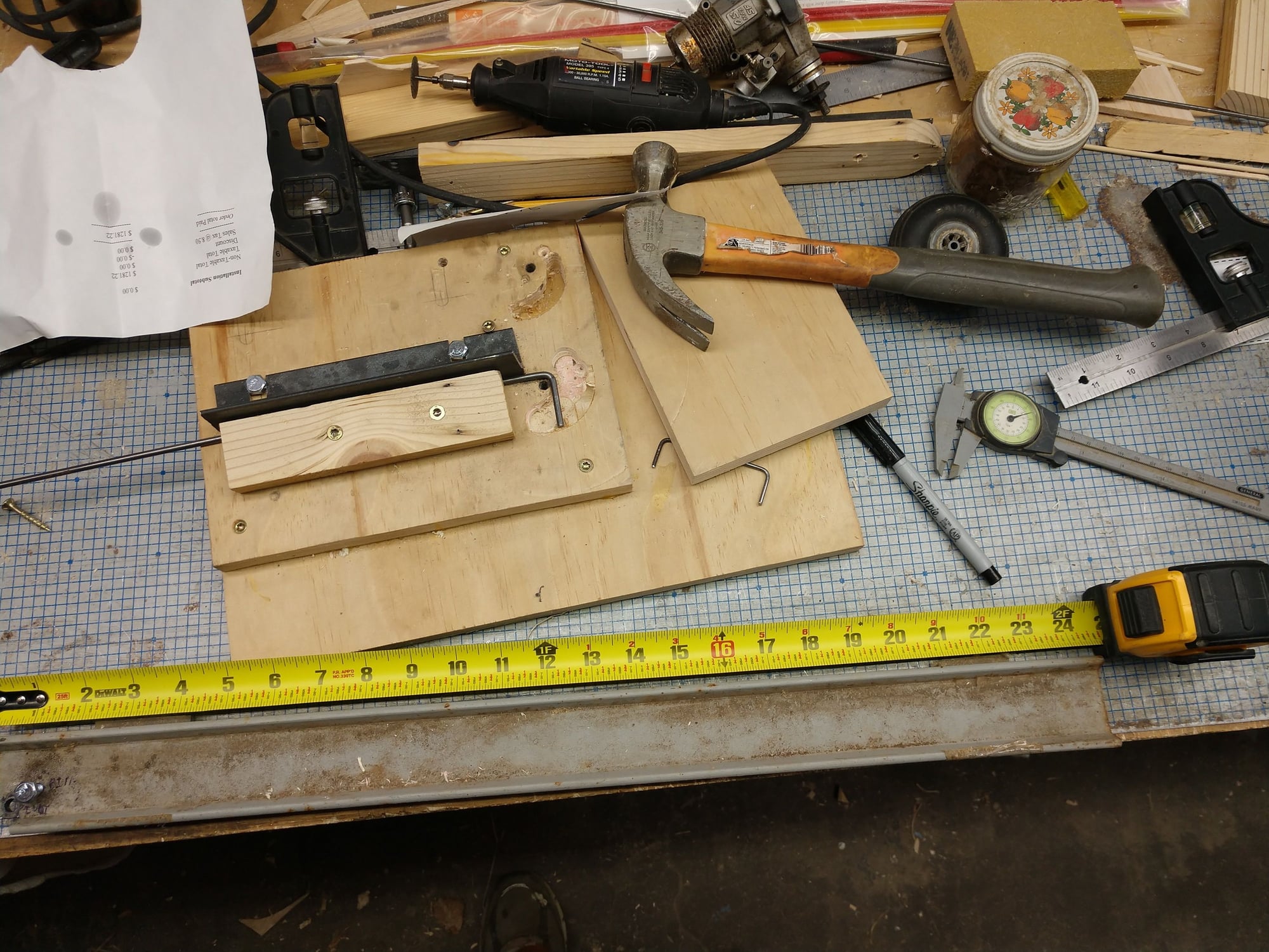
24" handle because that is the length of the bar to start with, No way did I want to do any extra cutting of this stuff
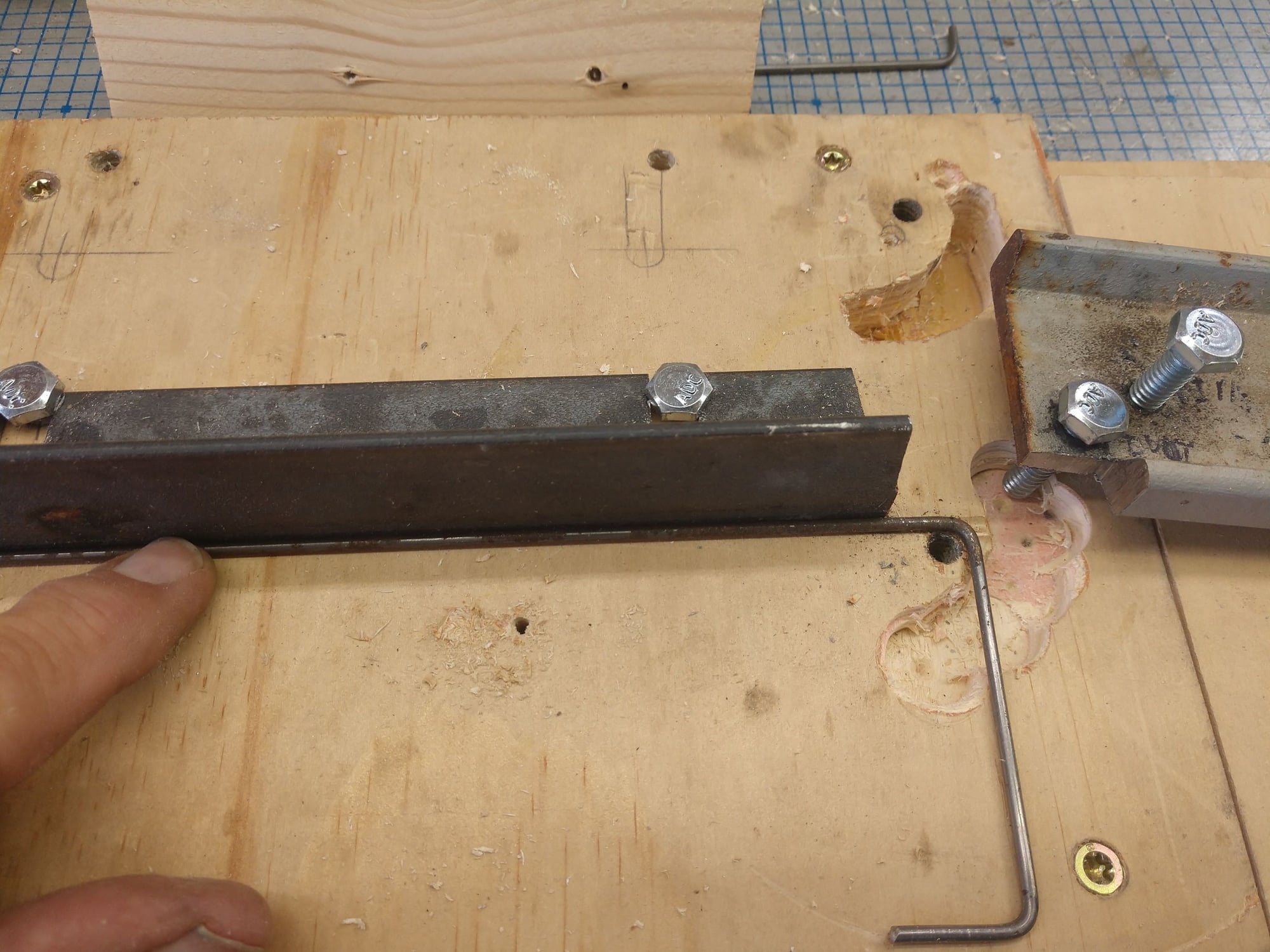
You can see the slot for the bending bolt. the bolt needs to go below the base to get flat bends. With sturdier construction so the was no play in the handle the slot might not be needed The hole at the top bend is tapped for a 1/4 20 bolt, This is the pivot.

Came out EXACT!
I may make another torque rod a bit longer with longer arms. This seems a bit small looking at it now.
that I got my ideas from. There are 3 PDFs.
Ken
I spent the day fooling around with making a piano wire bender.
I have always bent the wire with pliers, a vise, and a hammer to persuade the wire to my will with varying degrees of success.
I am going to have to bend some landing gear struts up at some point here. I have a couple of struts like the S.S uses, but they are way to short. I just checked the plans and it does not call out the wire size. Any know? I assume 1/8", really for no good reason.
I use 2 pieces of 3/4" ply glued together, because that is what I had on hand. I first tried a piece of 1" by 2" as my bending handle and some stainless steel screws. It had no trouble bending small the small Wire used for the torque rod, but I ended up with a twist.The screw heads prevented the wire stay flat on the base.
Next try I hunted for some steel bars I remembered that I had stashed some wheres. Hunted and just as I gave up hope of finding them, I glanced to my side and low and behold spotted them.
The 1.5" ply base was drilled and tapped for 1/ - 20 bolts for the backing bar and the pivot bolt.
I drilled a 1/4" hole for my pivot pin and a 13/64" near it to tap for a 1/4 - 20 bolt. Wrong geometry. Tried the other end and the spacing was off. So it was way, way easier to just use the bar than cut off the end and try it again. Took more care and laid the handle in the correct location and moved in the way I expected things to work. Marked the locations and LABELED what each hole was so I would drill the correct size holes in the correct location. I also took more time tapping the 1/4 - 20 hole.
To hold the wire in place I just screwed a piece of 1 by 2 on top of the wire and against the backing bar.
Success on the first try. The wire was dead on flat and Was the length between bends that I had marked.
I was a bit jazzed so decided to go for broke. 3/16" wire. I only did one bend as the pivot hole in the base stripped out. Ply is just to soft. Mable might work and I do have some. I did not clamp the bender down and on the 3/16" it was difficult to hold, but I still managed a 90 degree bend. My mark ended up at the end of the bend, not the middle. Maybe a better clamping system? 3/16" wire is the size used for the 1/3 scale Pitts Special I am going to build, so I now know I can bend the gear with a sturdier wire bender.
So I need a much better base. I'm thinking the wasted steel bar mounted to the ply base might work and I won't have to buy anything.
There is a thread that I got my ideas from. There are 3 PDFs.
Ken
The backing bar (left) has slots cut in it so it can be adjusted for different sizes of wire. The bolt closest to the bottom of the pic is the pivot pin. The wire bends around it. The bolt just above and right is the bolt that actually bends the wire It has to go below the top of the base so I used a Fostner drill bit and wood chisel to re-leave a slot for it in the base.
24" handle because that is the length of the bar to start with, No way did I want to do any extra cutting of this stuff
You can see the slot for the bending bolt. the bolt needs to go below the base to get flat bends. With sturdier construction so the was no play in the handle the slot might not be needed The hole at the top bend is tapped for a 1/4 20 bolt, This is the pivot.
Came out EXACT!
I may make another torque rod a bit longer with longer arms. This seems a bit small looking at it now.
that I got my ideas from. There are 3 PDFs.
Ken
The following users liked this post:
jnayjaso (04-05-2020)
03-15-2020, 03:59 PM
#61
Thread Starter
I bent a new torque rod today. Made the arms longer. Yeah definitely striped the pivot bolt hole in my bender. That's fine, it was only a proof of concept anyway. But I sure love bending wire this way. A steel or aluminum base would be the best, but Maple might be OK also.
The wire I have is a bit old and rusty so I cleaned it up before installing it.
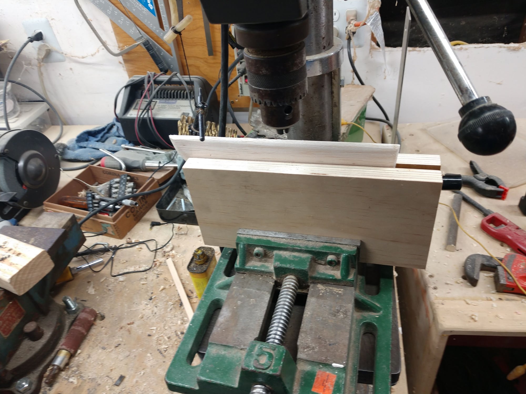
I also came up with a new method for me of drilling my torque rod holes. I cut 2 pieces of ply and clamped the control surface up in a vise on my drill press. Had to add a piece of 1/4" scrap at the bottom between the 2 pieces of ply. The control surfaces are 1/4". Checked level length wise with a bubble. set the drill stop, and the holes came out 100% perfect. I will remember this trick. No idea why I it never occurred to me before. Iv'e had those tools since the '80s.
The 2 elevator half's lined up perfect.
I started to work on the Pacific Ace I'm also build now, but ran out of time. Had errands to run.
Ken
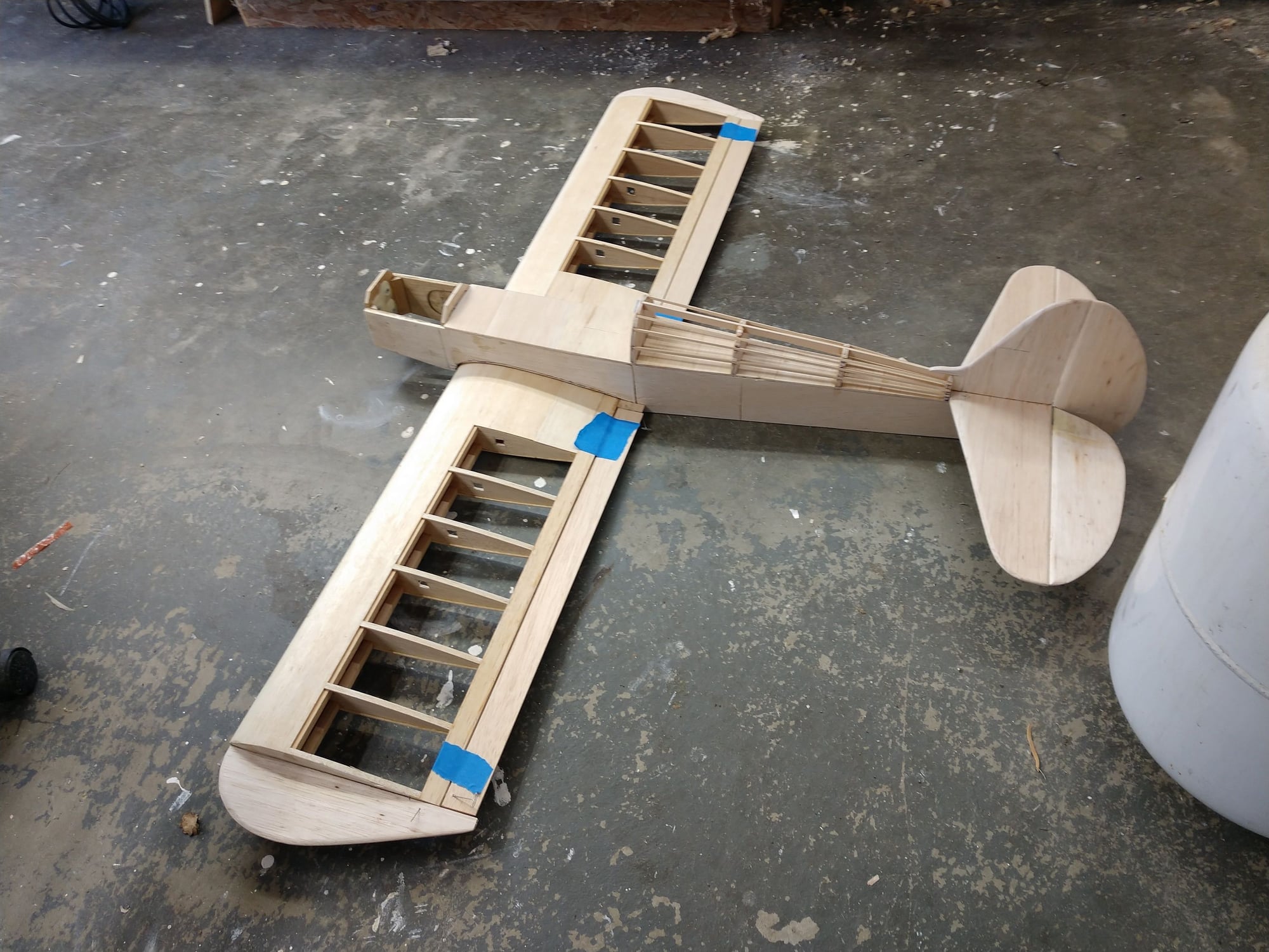
2 projects underway at the same time
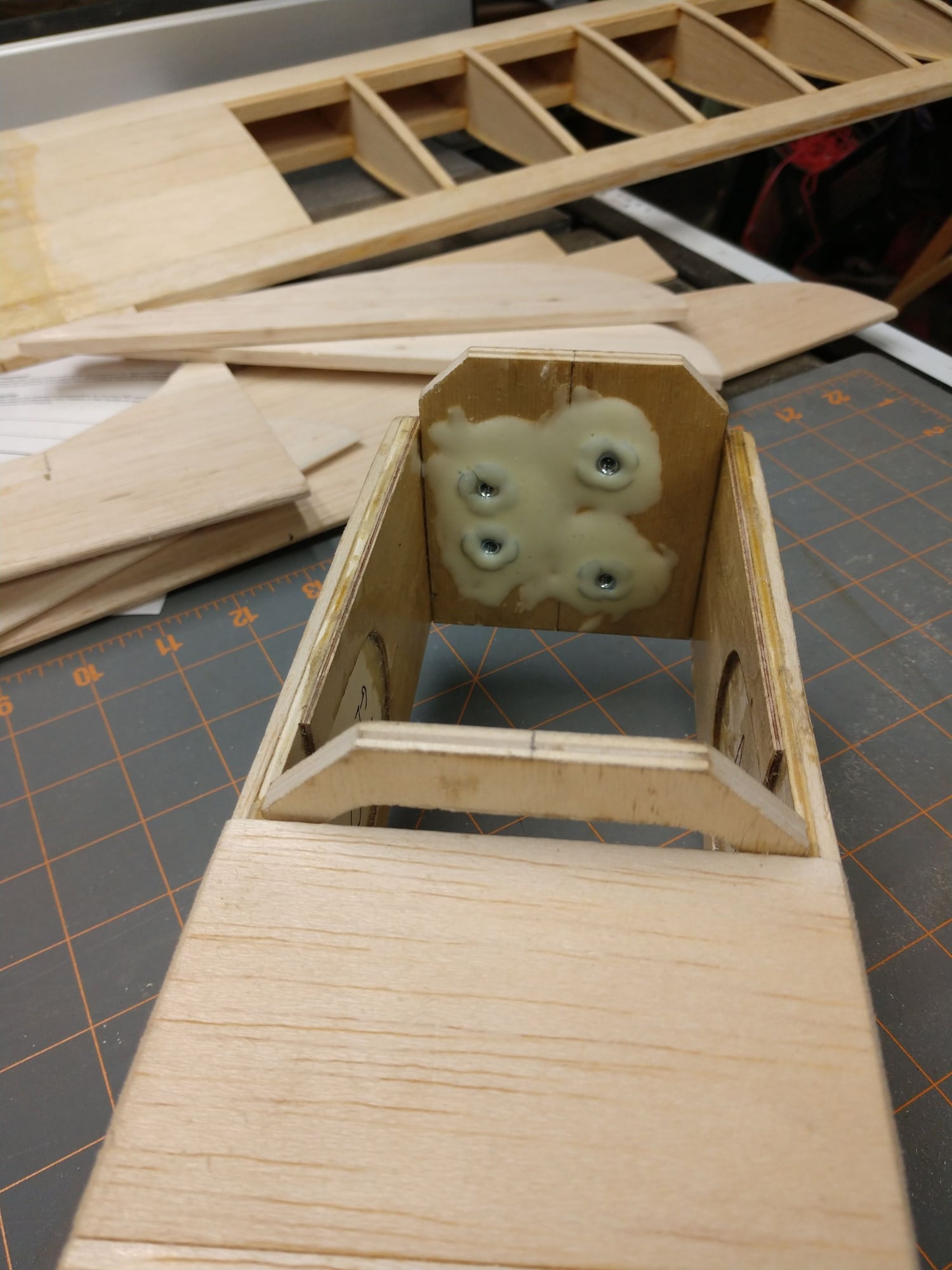
I did this yesterday. That'l hold 'em in there!
The wire I have is a bit old and rusty so I cleaned it up before installing it.
I also came up with a new method for me of drilling my torque rod holes. I cut 2 pieces of ply and clamped the control surface up in a vise on my drill press. Had to add a piece of 1/4" scrap at the bottom between the 2 pieces of ply. The control surfaces are 1/4". Checked level length wise with a bubble. set the drill stop, and the holes came out 100% perfect. I will remember this trick. No idea why I it never occurred to me before. Iv'e had those tools since the '80s.
The 2 elevator half's lined up perfect.
I started to work on the Pacific Ace I'm also build now, but ran out of time. Had errands to run.
Ken
2 projects underway at the same time
I did this yesterday. That'l hold 'em in there!
The following users liked this post:
jnayjaso (04-05-2020)
03-19-2020, 06:17 PM
#62
Thread Starter
I have slowed down some, but still going.
I epoxied the vertical fin to the the stab yesterday. But am not ready to epoxy the the tail assembly on yet. Want to wait till I am bolting the wing on.
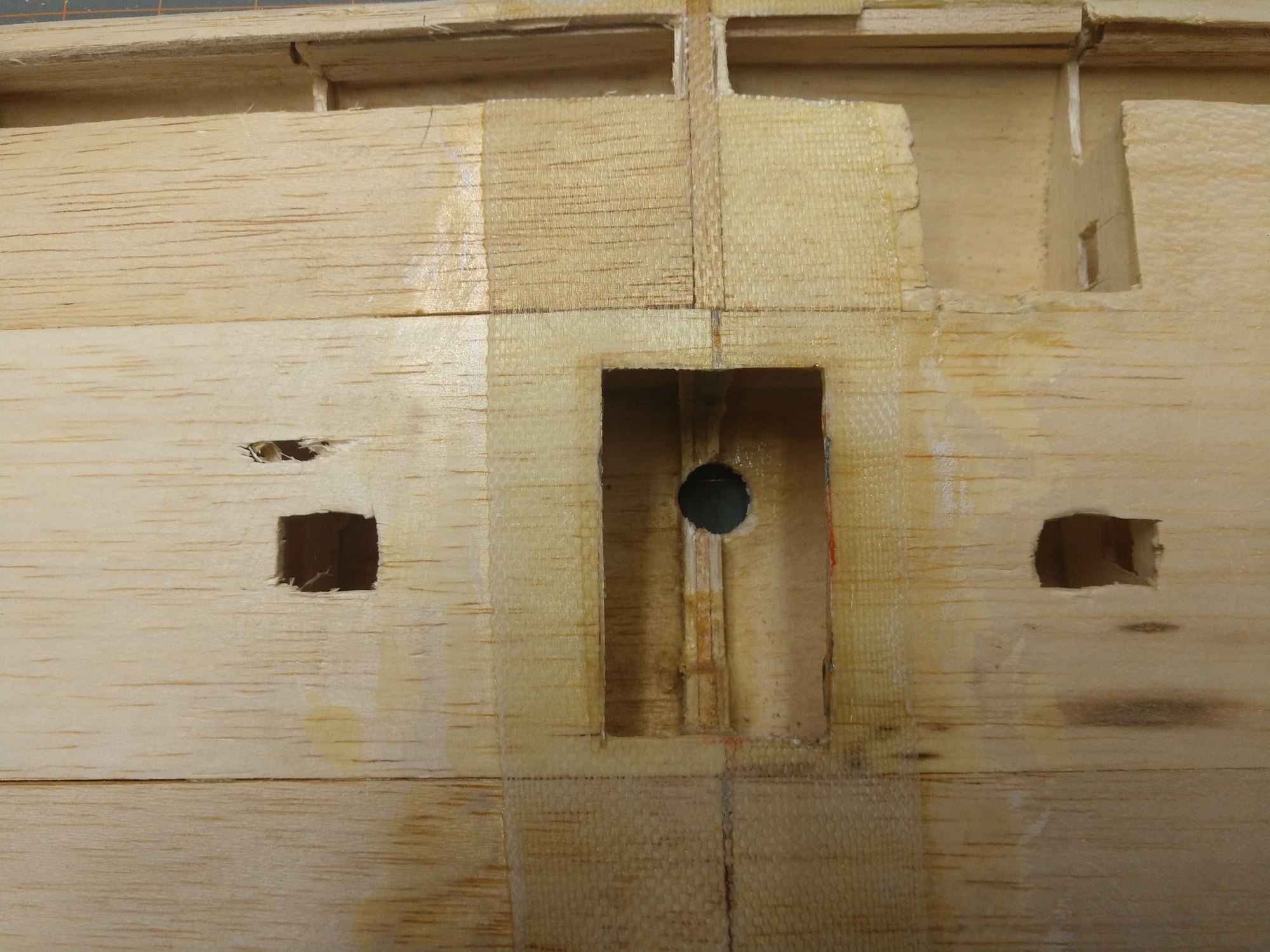
Speaking of wing,I epoxied the 1/4" ply wing dowel receivers to former #2. The wing dowels are cut off pieces of fiberglass arrow shaft. I have to order the Dubro Heavy-Duty Wing Mount Kit 1/4-20, to bolt the back of the wing to the fuse. Till then The tail feathers wont be epoxied on, alignment reasons.
I added some tri stock to the fire wall and front fuse sides.
I started something I have been putting off, I think just because it promises to be a pain. I cut open the bottom of the wing right behind the leading edge to install the bass landing gear mounting blocks. The job will be a little harder because the wing leading edge does not have a flat surface inside the wing. Not sure how to describe it. The L.E. is set in a birds mouth in the rib front edge. So the L.E. is rotated 45 degrees from vertical. I did not build this wing, but I have started using that orientation myself for many builds, I like it. The other thing that is going to make installing the gear mounts difficult is the wing was originally built as a high wing, so ZERO provision for this.
Ken
I epoxied the vertical fin to the the stab yesterday. But am not ready to epoxy the the tail assembly on yet. Want to wait till I am bolting the wing on.
Speaking of wing,I epoxied the 1/4" ply wing dowel receivers to former #2. The wing dowels are cut off pieces of fiberglass arrow shaft. I have to order the Dubro Heavy-Duty Wing Mount Kit 1/4-20, to bolt the back of the wing to the fuse. Till then The tail feathers wont be epoxied on, alignment reasons.
I added some tri stock to the fire wall and front fuse sides.
I started something I have been putting off, I think just because it promises to be a pain. I cut open the bottom of the wing right behind the leading edge to install the bass landing gear mounting blocks. The job will be a little harder because the wing leading edge does not have a flat surface inside the wing. Not sure how to describe it. The L.E. is set in a birds mouth in the rib front edge. So the L.E. is rotated 45 degrees from vertical. I did not build this wing, but I have started using that orientation myself for many builds, I like it. The other thing that is going to make installing the gear mounts difficult is the wing was originally built as a high wing, so ZERO provision for this.
Ken
The following users liked this post:
jnayjaso (04-05-2020)
03-20-2020, 04:13 PM
#63
Thread Starter
I solved the problem of mounting the L.G. blocks to the wing L.E. I cut some tri stock down so it would fit to the wing leading edge. Took a few tries to get it right. Sure loving that little 4" Dremel table saw. I glued the tri stock to the upper and lower surfaces of the l.e. to make a flat to glue the l.g. blocks to. I think this is going to work.
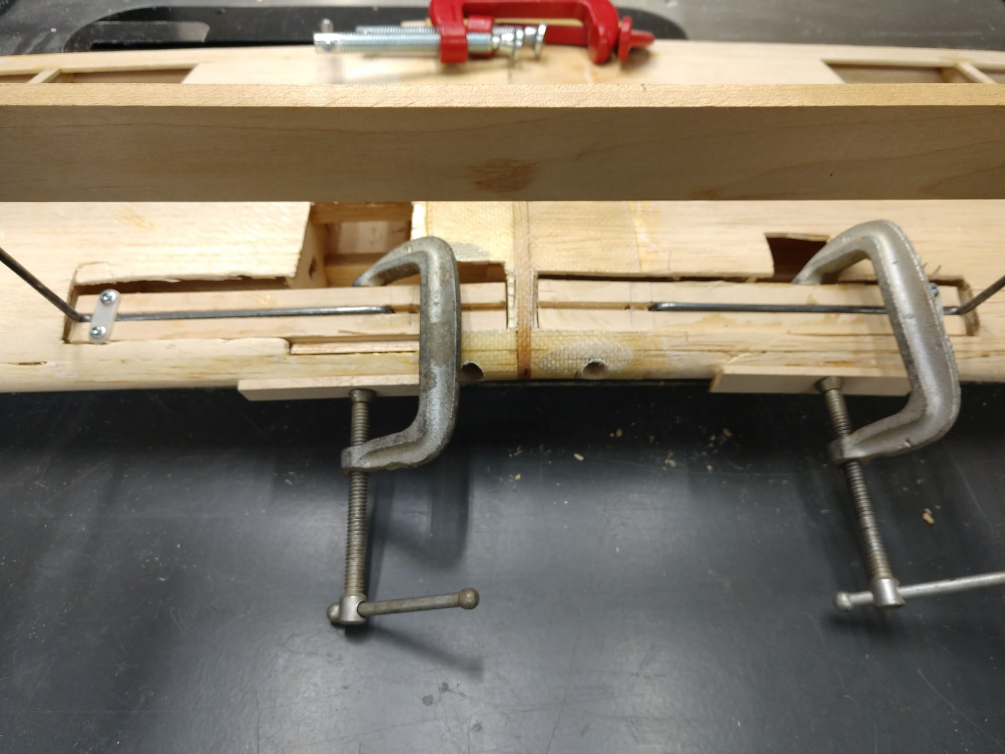
I had one l.g. block in a junk bin. Can't go out and get material now. This entire state is on lock down due to the Corona virus. I doubt that the hobby shop is even open for the same reason. Did not go flying either, that is not essential business, but dang it, it sure feels essential to me. So I laminated up some 1/8' bass that I ripped to the same width as the l.g. block I have. I makes a great template. So I lamented 2 strips of 1/8" bass together with epoxy. I also laminated a shorter piece of bass to the back opposite side of the block. The wing dowels need to go thru the blocks at least a little ways. Maybe the wing dowels will be strong enough to just penetrate into the blocks a short distance I ripped the 3rd strip and epoxied it to the other 2 with a piece of 1/8" music wire between the 2 strips to act as a spacer. That gives me a ready made slot for the l.g. wire to lay in. I have not yet drilled the hole for a leg of the l.g. wire to go thru. I should make the l.g. wires first I think. To do that I need to rebuild my wire bender. I ruined the pivot hole testing to see if I could bend 3/16" wire. A piece of 1/4" steel is in order for the pivot pin's hole. The hard ware stores are still open.
I am going to use 2 servos for the ailerons, so they are mounting out board. I tried to drill with a fostner bit servo wire holes in the ribs. That was a big no go. No way to get the bit in between ribs. I just ended up cutting square-ish holes for the wire wires. The rib in between the center ribs and the rib at the end of the center section sheating was a real bugger. I finally said nuts on it and cut a slot in the center section sheating big enough to work my knife thru to cut the hole I needed. I really hate cutting extra holes, but I just could not do the job till then. Well it isn't like there weren't already plenty of holes to fix.
I really did not spend a lot of time working in the garage on planes today. This lock down has me feeling a bit antsy. Thinking of buy a flight sim, since I can't go out and fly. But the down side there is that is funds I would otherwise use for building. So we'll see.
Ken
Last edited by flyingagin; 03-20-2020 at 04:18 PM.
The following users liked this post:
jnayjaso (04-05-2020)
03-22-2020, 05:01 PM
#64
Thread Starter
My modified / repaired wire bender works a charm now. I removed the section of plywood that held the pivot pin. Dado cut it out with my stacked Diablo dado set set. How in heck I ever lived with out one of these beats me. I then glued in some Mable, Drilled and tapped it. I also switched to a short piece of steel plate to clamp the wire. I was still concerned that the wire could drag towards the pivot pin as I bent it, So I provided a relieve on the bottom end to get a C clamp in. Now the wire is held 2 ways. It does not move now.
With that done I proceed to make a gear strut. Looked great, was easy to do. So I got off the vertical leg that goes thru the l.g. block. Or I thought I was when I cut it. WRONG ANSWER! I cut the wire in the wrong spot, thus ruining it. Crap. But I had enough left on that piece of wire to make 2 more. And I checked my storage and I have 2 more 36" pieces of 1/8" to bend up some L.G. for the Pacific Ace I am also building. Can't go to the hobby shop for more due to the virus. I'm in California, and we are locked down here, even the flying field is closed.
It really only took maybe a 1/2 hour to bend and cut the 2 L.G. struts. And that exactly match. Woo Hoo! Never been able to do that by hand before.
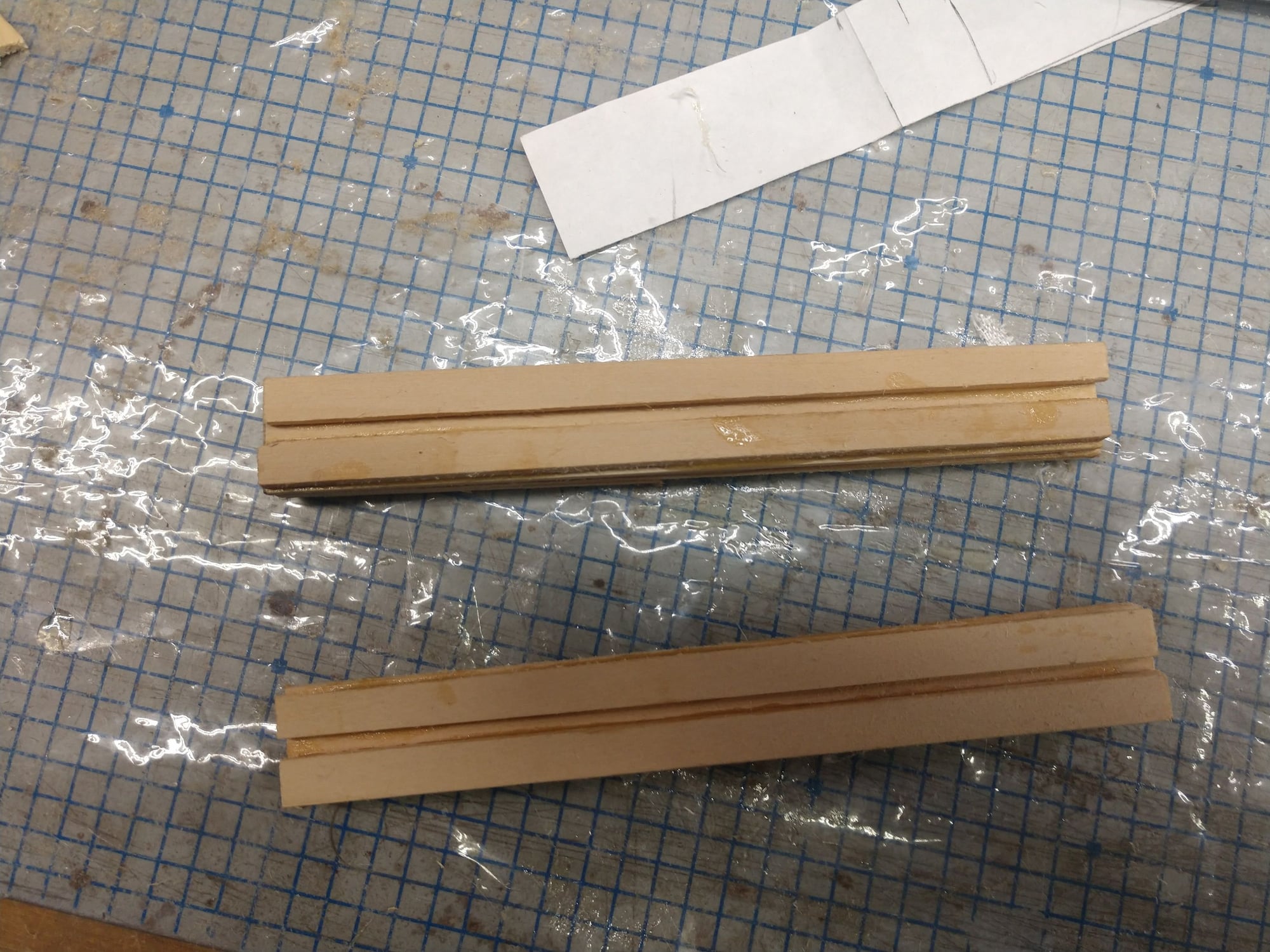
The struts need to angle forward to position the wheels correctly. I'm still working on that. I can bend the legs forward or I can mount the gear blocks angling forward. I strongly leaning that way. So I have epoxied a 1/8" face plate of Bass to the front sides of the gear blocks. I can the set up a jig and sand the face plate to an angle that will give me the correct strut angle. Or at least I think I can.
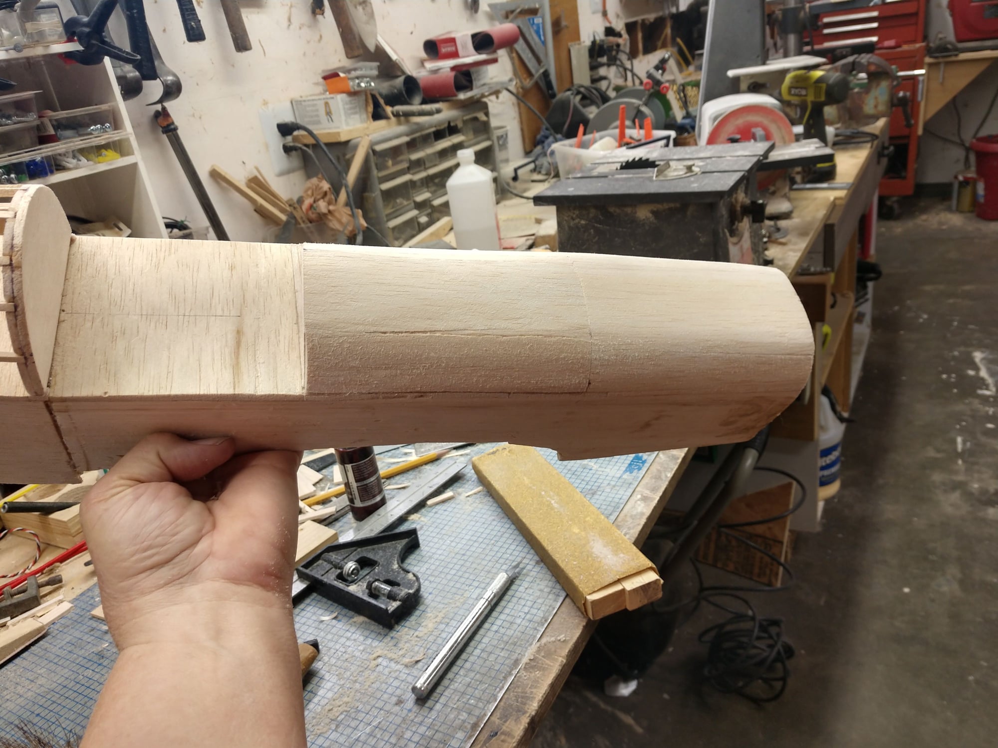
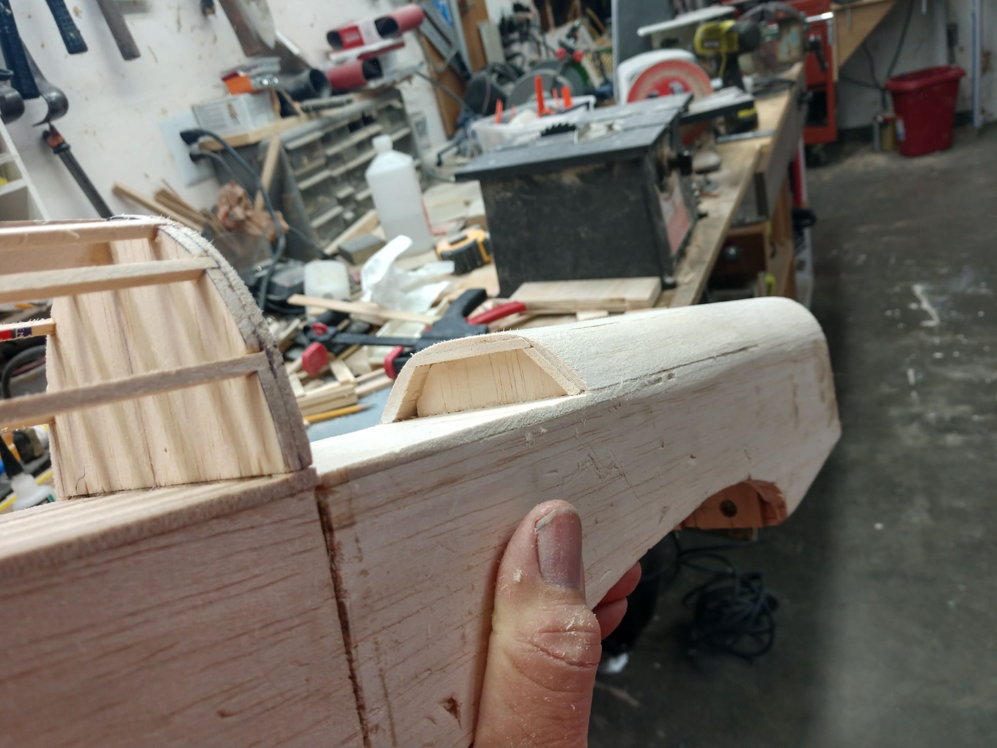
I then closed off the top of the nose.
Canopies are not no longer available for this plane. Also I made it wider than stock so a non starter. I don;t have the ability to pull a canopy at this time. I may acquire that knowledge and equipment later on, but not now. So I am going to have an open cockpit with a windshield. Still need to extend the top nose section back to roughly match the plans. I will carve a block and hollow it out.
Ken
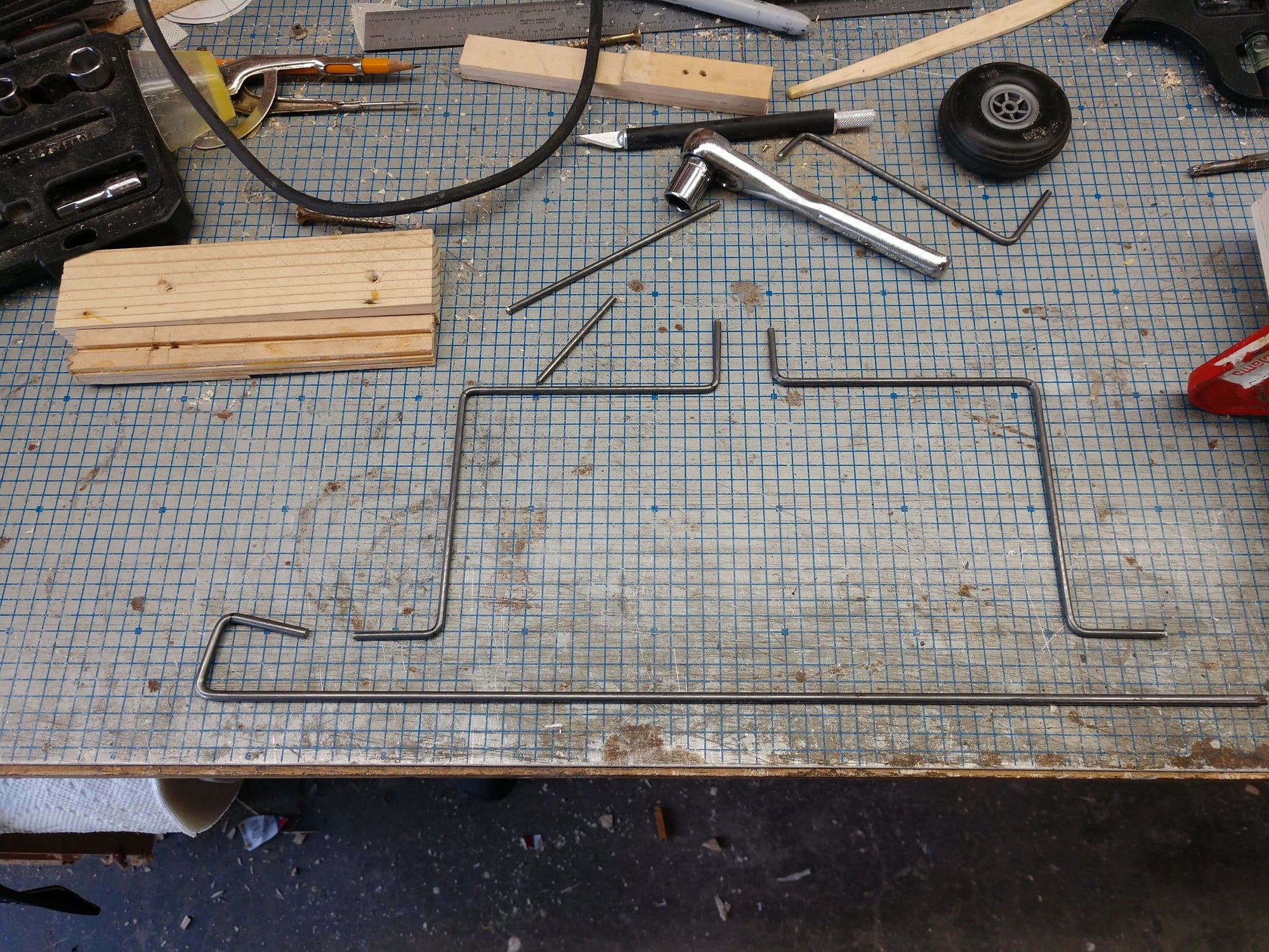
The 2 landing gear struts.. The bottom wire is 3/16" wire to see if I could bend it, YEP!
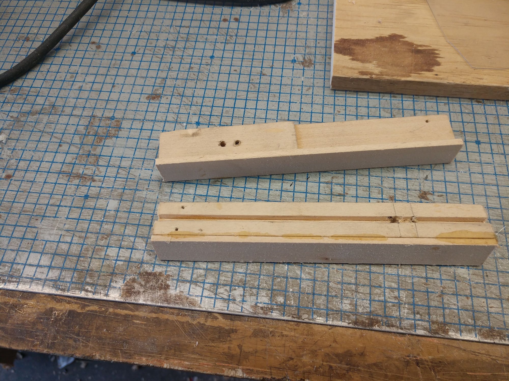
Added a face to sand to an angle and set the strut angle.
Did a dry fit Way to much aileron area at this time (double wide stock) May cut the span in half and add flaps inboard
With that done I proceed to make a gear strut. Looked great, was easy to do. So I got off the vertical leg that goes thru the l.g. block. Or I thought I was when I cut it. WRONG ANSWER! I cut the wire in the wrong spot, thus ruining it. Crap. But I had enough left on that piece of wire to make 2 more. And I checked my storage and I have 2 more 36" pieces of 1/8" to bend up some L.G. for the Pacific Ace I am also building. Can't go to the hobby shop for more due to the virus. I'm in California, and we are locked down here, even the flying field is closed.
It really only took maybe a 1/2 hour to bend and cut the 2 L.G. struts. And that exactly match. Woo Hoo! Never been able to do that by hand before.
The struts need to angle forward to position the wheels correctly. I'm still working on that. I can bend the legs forward or I can mount the gear blocks angling forward. I strongly leaning that way. So I have epoxied a 1/8" face plate of Bass to the front sides of the gear blocks. I can the set up a jig and sand the face plate to an angle that will give me the correct strut angle. Or at least I think I can.
I then closed off the top of the nose.
Canopies are not no longer available for this plane. Also I made it wider than stock so a non starter. I don;t have the ability to pull a canopy at this time. I may acquire that knowledge and equipment later on, but not now. So I am going to have an open cockpit with a windshield. Still need to extend the top nose section back to roughly match the plans. I will carve a block and hollow it out.
Ken
The 2 landing gear struts.. The bottom wire is 3/16" wire to see if I could bend it, YEP!
Added a face to sand to an angle and set the strut angle.
Did a dry fit Way to much aileron area at this time (double wide stock) May cut the span in half and add flaps inboard
Last edited by flyingagin; 03-22-2020 at 05:04 PM.
The following users liked this post:
jnayjaso (04-05-2020)
03-24-2020, 02:24 PM
#65
Thread Starter
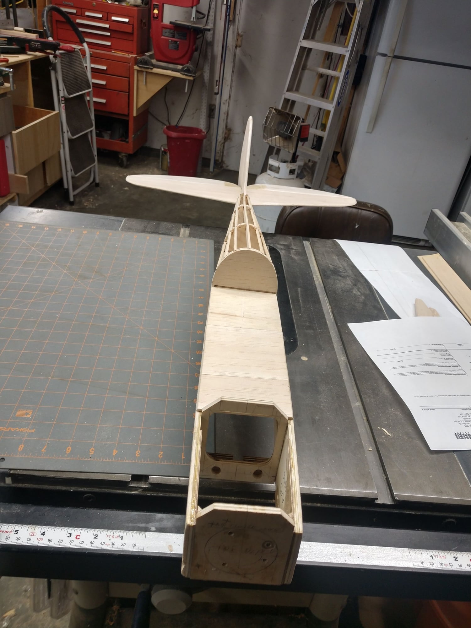
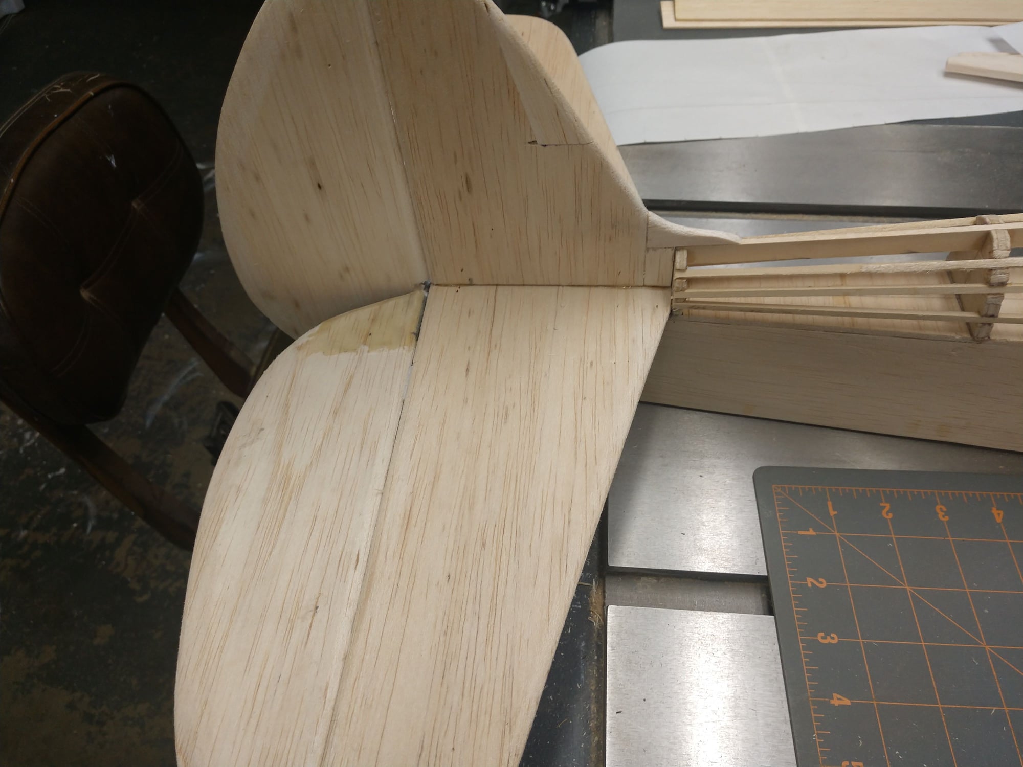
I epoxied the tail feather on yesterday after gluing the wing tips on. I did it in that order so I could place a small bubble level on a wing tip and thus level the wing and plane (with the wing mounted, well front mounted and back taped on).
Also i extended the front top sheeting to roughly the wing mid point.
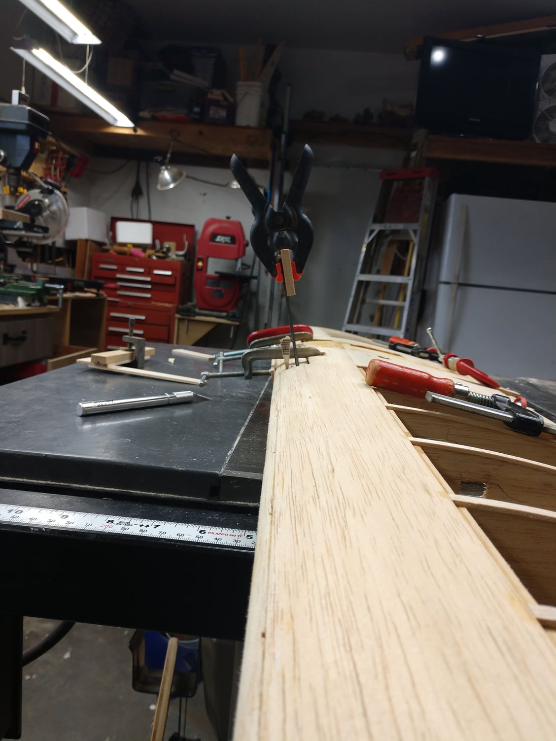
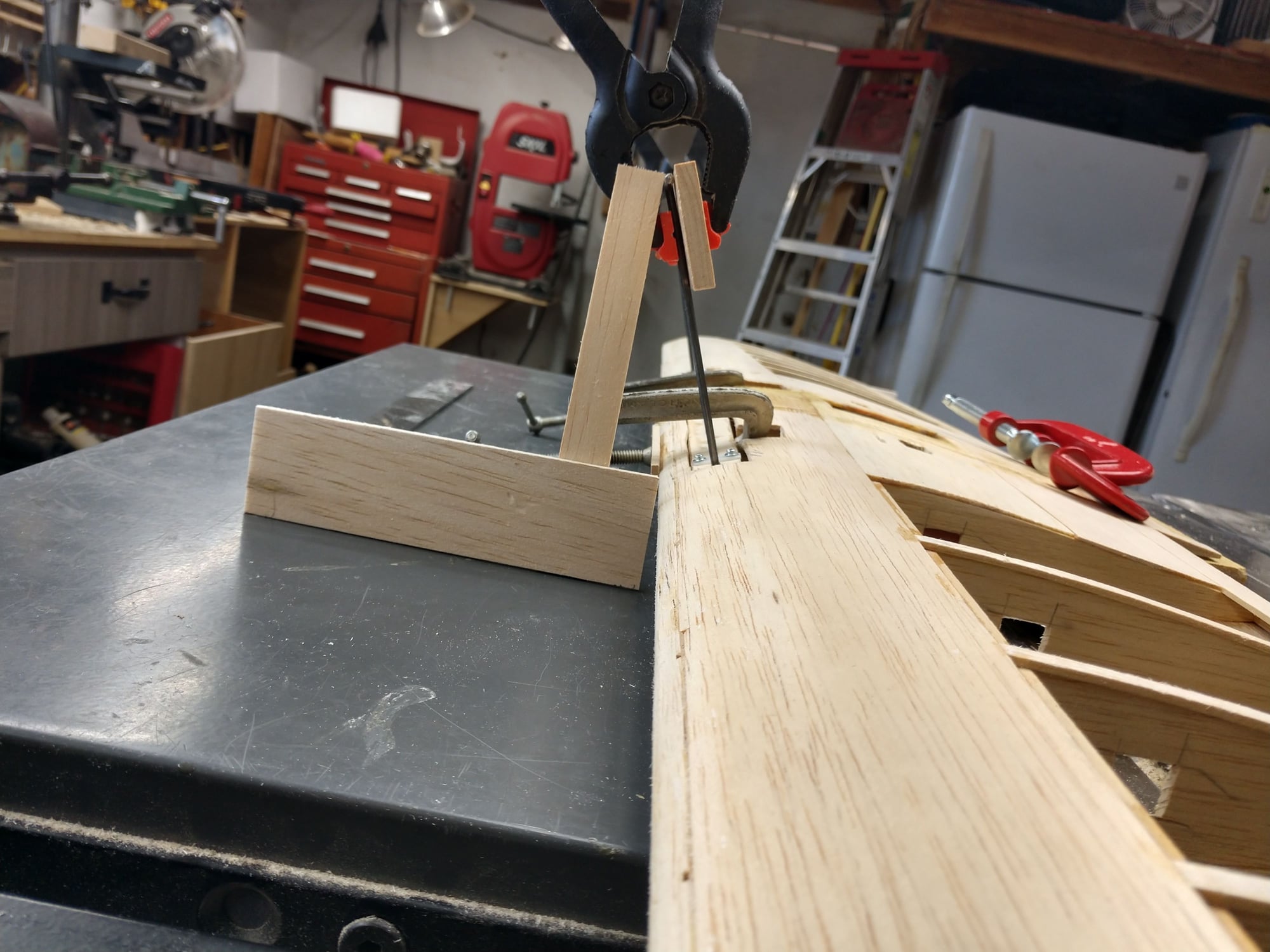
Today It's landing gear blocks time. This was a very, very fiddly thing to do. I clamped the gear legs at the wheel axle point to a flat piece of 1/4" maple I had handy. That got the legs close to parallel to each other. That's when it got fiddly. Spent maybe an hour dry fitting to get the correct alignment. Now got a bunch of epoxy on the gear blocks, blocks clamped up, hoping like heck that nothing shifts.
I can slightly bend the legs if I need to, just prefer not to.
Ken
Will iron some black MonoKote into the cockpit area
The recessed area will get some black paint
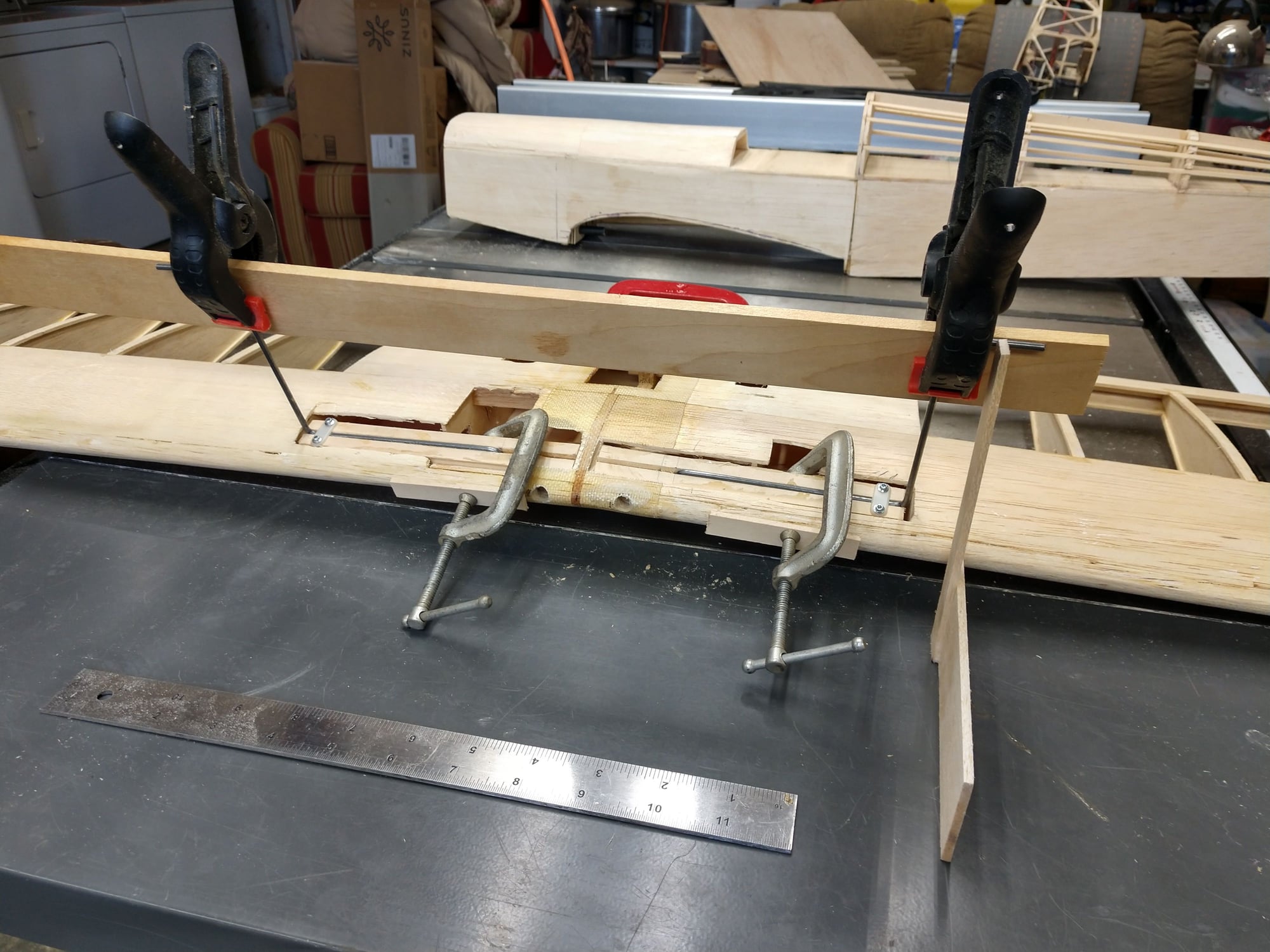
Sight down the legs they are at the same angle
This axle has a very slight toe in, I think I will give the other one a twist also.
Also i extended the front top sheeting to roughly the wing mid point.
Today It's landing gear blocks time. This was a very, very fiddly thing to do. I clamped the gear legs at the wheel axle point to a flat piece of 1/4" maple I had handy. That got the legs close to parallel to each other. That's when it got fiddly. Spent maybe an hour dry fitting to get the correct alignment. Now got a bunch of epoxy on the gear blocks, blocks clamped up, hoping like heck that nothing shifts.
I can slightly bend the legs if I need to, just prefer not to.
Ken
Will iron some black MonoKote into the cockpit area
The recessed area will get some black paint
Sight down the legs they are at the same angle
This axle has a very slight toe in, I think I will give the other one a twist also.
The following users liked this post:
jnayjaso (04-05-2020)
The following users liked this post:
jnayjaso (04-05-2020)
03-26-2020, 06:27 PM
#67
Thread Starter
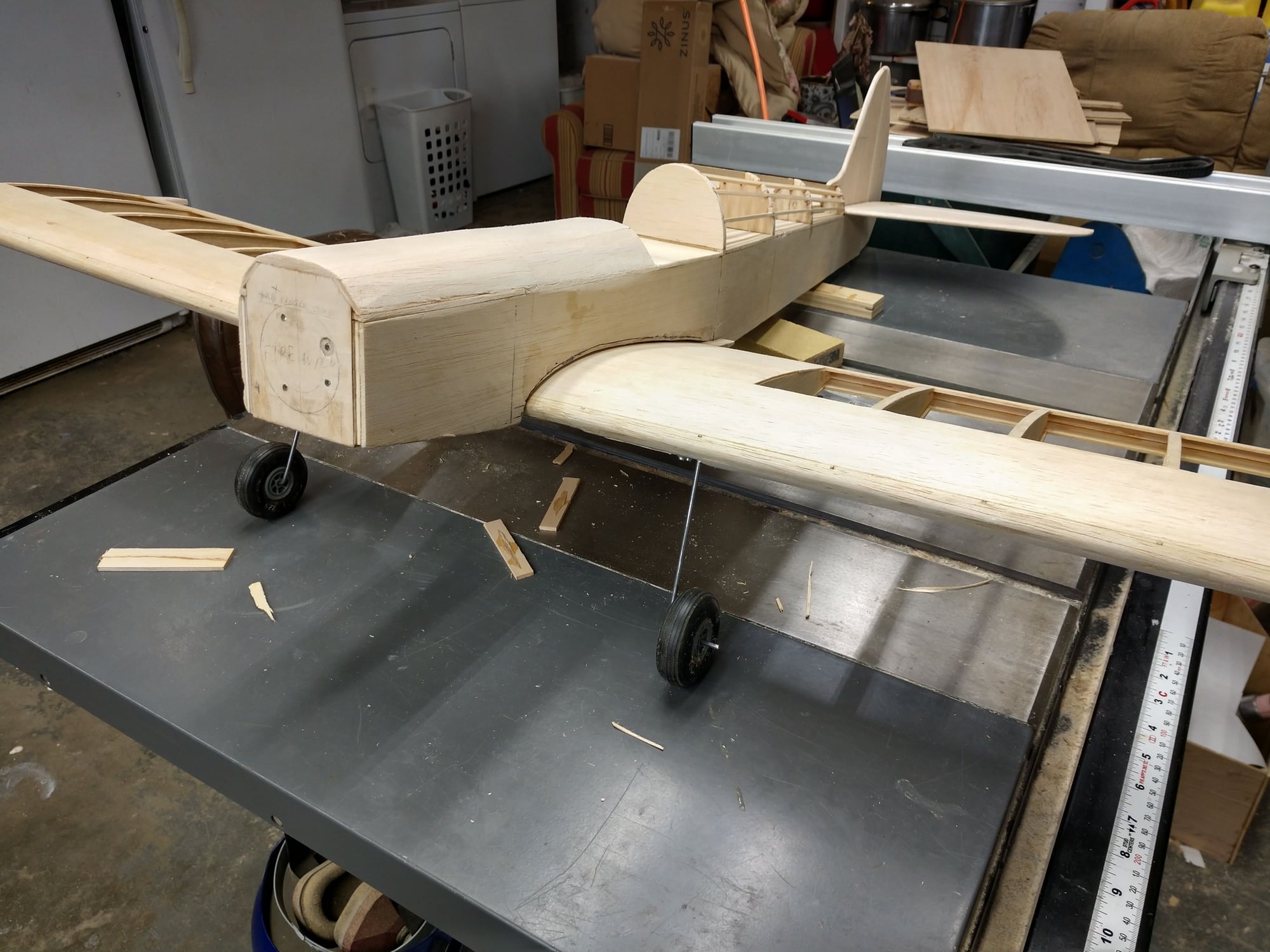
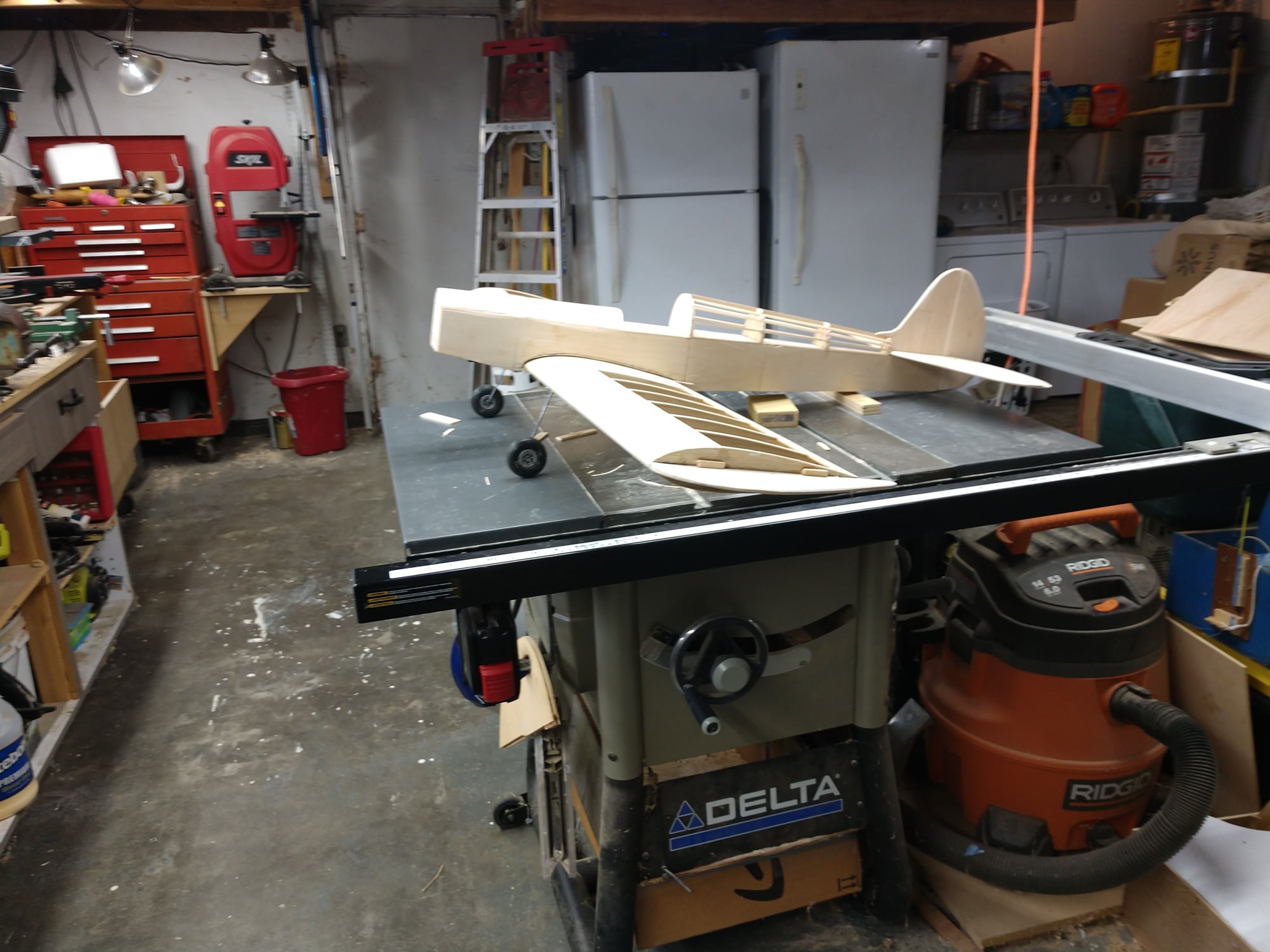
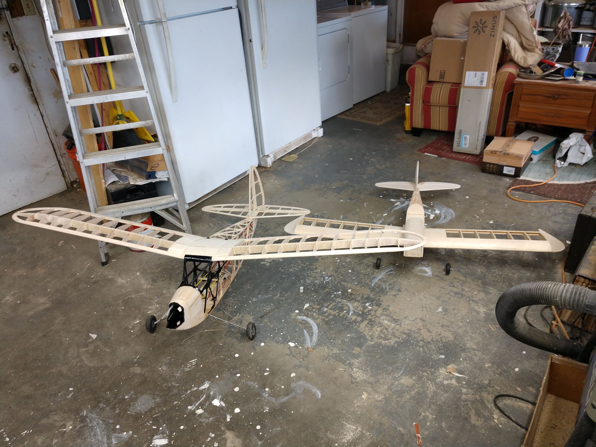
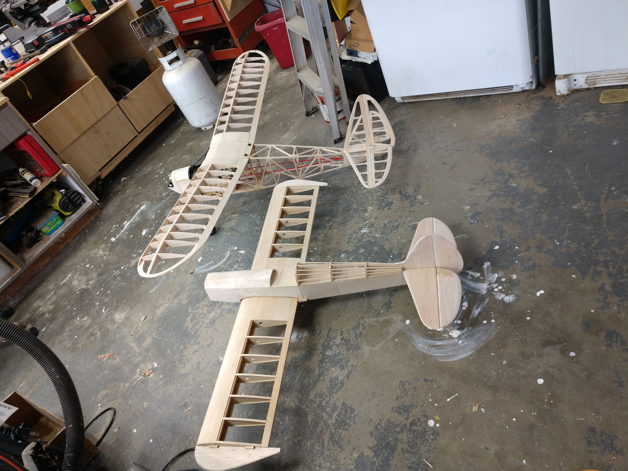
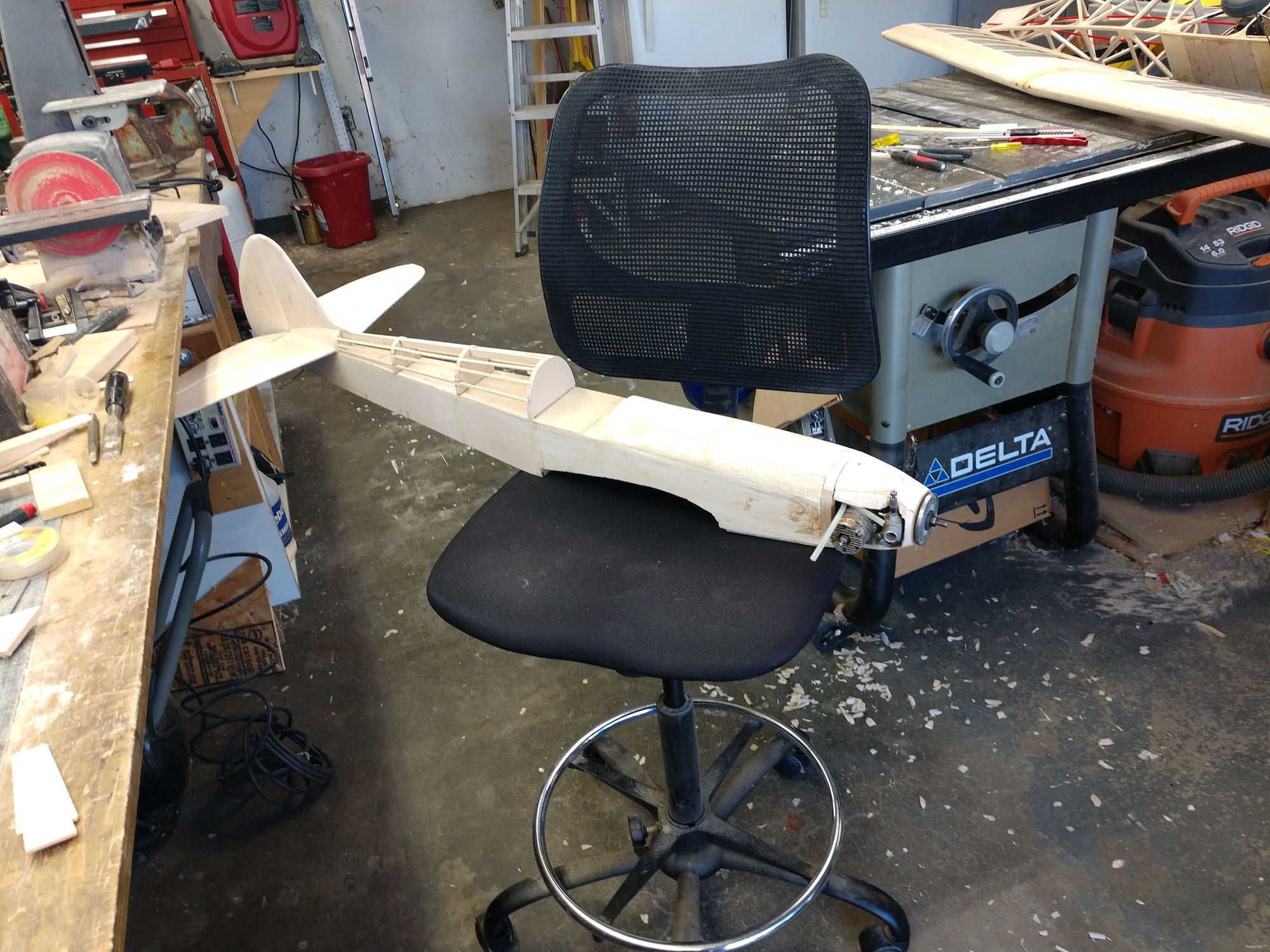
Did not work on the S.S. today, but did get two pics. posed both the S.S. and the Pacific Ace 74 together. The little time I had to do airplane work was spent on the main landing gear of the P.A.
Ken
Ken
The following users liked this post:
jnayjaso (04-05-2020)
The following users liked this post:
jnayjaso (04-05-2020)
03-27-2020, 05:30 PM
#69
Thread Starter
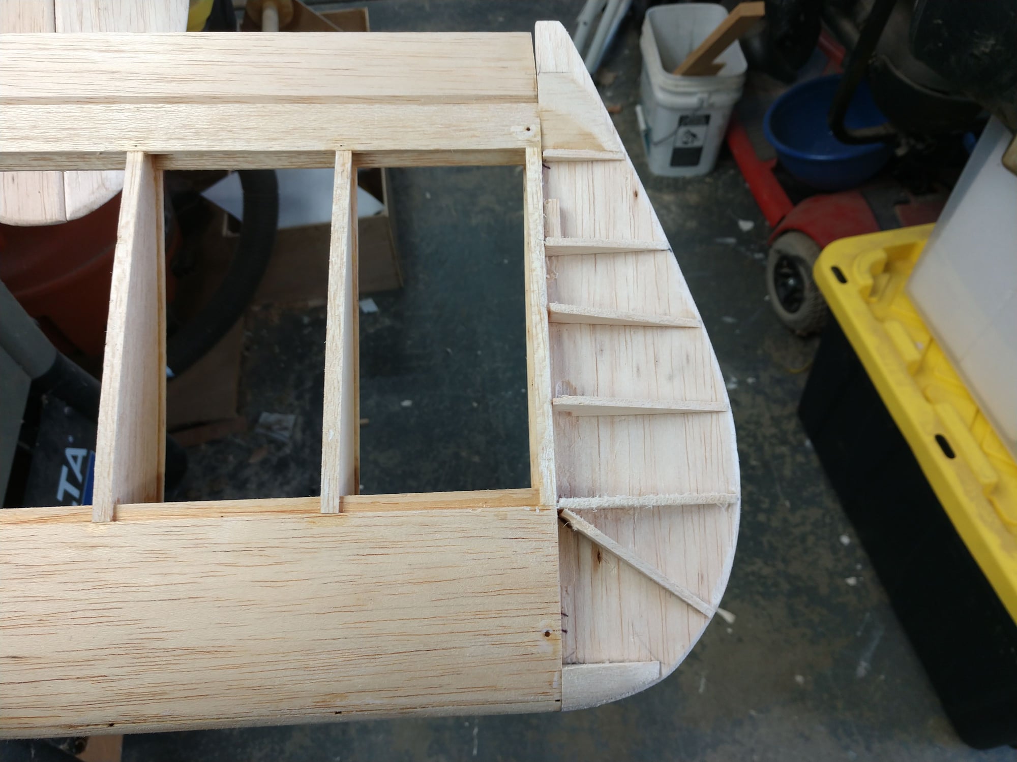
Added formers (?) triangles to the wing tips, To get them ready for covering. These will carry the film with out sags.
Then I hung the ailerons. I needed them on so I could match the rear of the wing tips to the ailerons taper.
I added some Bass fill to the bottom of the L.G. blocks so they would be flush with the bottom of the wing . I will need to add a fill to the L.G. wire slots so as to now raise the wires flush with the bottom of the L.G. blocks.
The it was time to patch all of the holes in the bottom of the wing, some I (most) made and some already there. Tedious and frustrating at times. But I got all but one at the wing tip done and rough sanded. Will do some putty work. And the whole center wing section will need to be glassed.
Ken
03-28-2020, 09:00 PM
#70
Thread Starter
My wife bought a gram scale for her cooking needs. It arrived today. And I always thought a pinch, a handful, a dash, or a cup or whatever was good enough. Maybe that's why I not the cook.
So I just borrowed it to weigh the S.S
I had to do it sections. But here are the numbers.
The fuse with no radio installed but also includes the tail feathers is 417 grams. = .9193 Lbs. = 14.709 ounces. This does include the servo tray.
The battery will be a 850 850mAh LIFE battery Weight 50 grams - 1.8 oz
The servos are Hitec HS-322HD Weight 1.5oz = 43 grams times 5 = 215 grams = .4740 Lbs = 7.5839 ounces.
The rx is 5 grams.
The complete radio gear weight should be about 270 grams = .5952 Lbs = 9.5240 ounces.
The wing weighs 421 grams = .9281 Lbs = 14.85 ounces Center section still needs fiber glass and covering. Not yet covered.
The engine and motor mount weigh 494 grams = 1.0891 Lbs = 17.425 ounces. Includes muffler.
The 2 landing gear struts and wheels weigh 80 grams = .164 Lbs = 2.8219 ounces.
So the total wight should be a little more than 1332 grams = 2.9366 Lbs = 46.985 ounces.
So the grand total without covering is grams = 1682 grams = 3.7082 Lbs = 59.31 ounces.
The wight should not go up much. I have to make a engine cowl yet and fiber glass the wing center section. Also the wing servo mounts and cover need to be made.
I am pleased with the wight.
Ken
03-29-2020, 08:03 AM
#71
Thread Starter
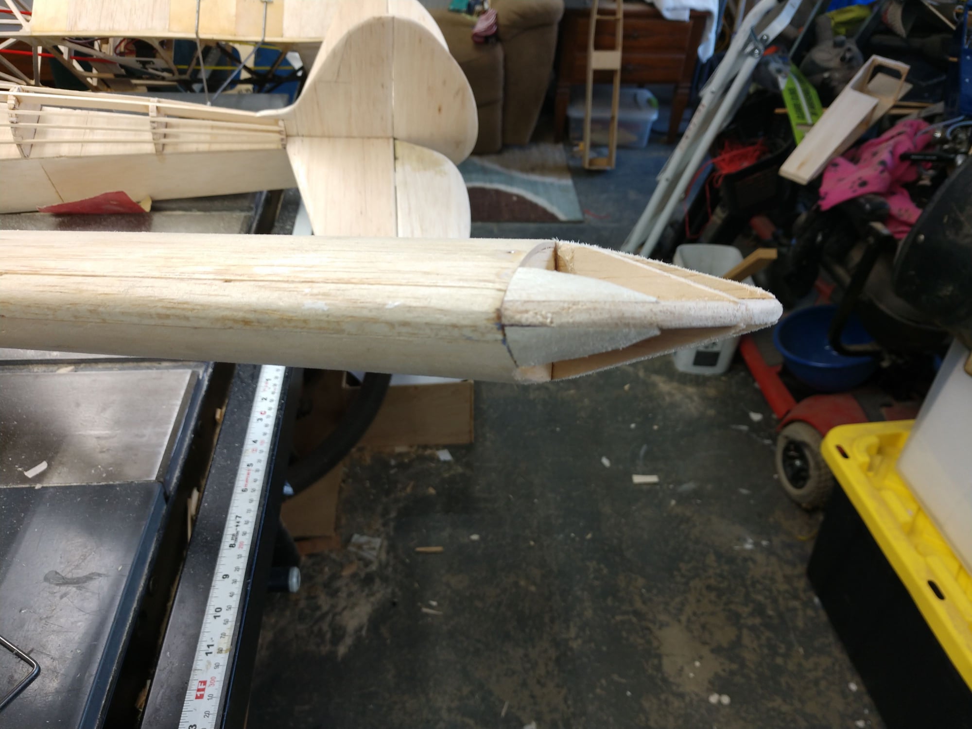
Tail blocks between the stab and vertical fin added. They were also hollowed out, but being so small were pretty light to start with. Should also re enforce that joint substantially.
Ken
Ken
03-29-2020, 08:36 AM
#72
Thread Starter
I just looked up the specs for the GreatPlanes S.S.
There specs are Weight4.75-5.0 lb (2.2-2.3 kg) Wing Loading19.7-20.8 oz/ft� (59.7-62.9 g/dm�)
So I am doing really good. Won't be much more weight added at this point.
Ken
There specs are Weight4.75-5.0 lb (2.2-2.3 kg) Wing Loading19.7-20.8 oz/ft� (59.7-62.9 g/dm�)
So I am doing really good. Won't be much more weight added at this point.
Ken
03-30-2020, 05:00 PM
#73
Thread Starter
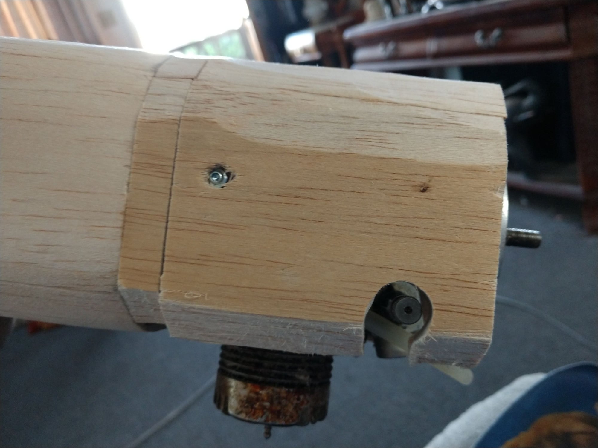
I plumbed up the fuel tank, and I have the fuel tank hanging in loosely at this time so I could see were to put the holes for the fuel lines and the throttle sleeve.
Then I made up a bottom cover for the fuel tank compartment. The cover is lite ply with some balsa added to it so I could slightly round it over. I decided against permanently gluing it on, so it is screwed on with 8 screws. This will add stiffness to the compartment. But truth be told it is stiff as heck already. If I need to get at the tank or plumbing I can with out a struggle. the tank will get cushioned with RC foam to isolate it from vibration.
Now I am at I point I have never liked doing, Making a engine cowl. I am just adding some 1/2" stock and then carve off a bunch. I used my last scrap 1/2" at this point. But I do have a virgin 1/2" x 4" x 36" sheet that I was holding back for a future control line plane. Problem is due to the virus the hobby shops are closed. So mail order only. Well I am not paying to ship one sheet. I am going to use the sheet I have.
The cowl will be held on with 3 screws. There are 3 bass pads to accept the screws. I did think about making a glass cowl, but again the lack of supplies. I have lots of glass, but no west systems epoxy and no foam for a one off mold although I can get that at the local Home Depot. I do have some appearance with making one off glass cowls. Once I have the internal clearances for the cowl and the external shape, then I will start removing as much internal excess wood as I can get away with. That will then get one layer of fiber glass.
Cowls are just a pain in the rear.
Ken
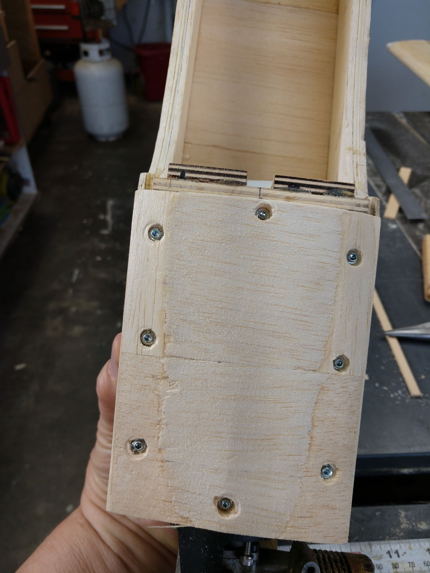
03-31-2020, 05:26 PM
#74
Thread Starter
I was a busy guy today. Got up early to go to Walmart during their senior and handicapped hours. I'll give them a thumbs up for it. I was able to pick up scrips and do some small shopping with no line and not many people around me. Easy to keep my distance.
Then Hospice was out twice today for mom. The nurse seems to feel that mom's time is short, maybe as little as a few weeks. That is what i was alluding to with the "life interuptus occurs" comment in the last post. When that happens we will try to sell the house as soon as we can and then get the bloody H*ll out of this state. Head to Kansas.
I worked on our travel trailer some (a 27 footer). That went way easier and faster than I expected. A couple of those things that you think are just going to be a royal Pain. And they weren't, total shock.
That left time to work on the S.S. cowling, Even that went better than I had thought it. Still have a bit more final shaping and sanding,. Once I am satisfied with the external shape, I will then start removing the excess material from the inside to lighten it and give a smoother more even internal shape for a layer of fiber glass.
I seems fairly lite right now but, just for giggles I intend to weigh it before and after just to see how much effect carving out the inside makes.
Ken
04-01-2020, 06:49 AM
#75
Join Date: May 2015
Posts: 9
Likes: 0
Received 0 Likes
on
0 Posts
Looks like you are doing a good job.
I'm almost finished a 60 size GP sportster.(Needs battery mount and, arming switch. Not quite as much work as cutting everything, but still not a beginners kit.
I put 4 servos in the wing and also had to go back and patch a bunch of holes. Kept forgetting to do something.
Its powered with Power 60 motor - 6s 5000 lipo and came in at 7 3/4 lbs. The spec call for max 7 1/2 lbs but that was for glo with an empty tank.
I've got the servos set up with glider functions (Flaps, synced ailerons, crow ) Some might say its too much for someone that doesn't fly that well, but I cant resist.
I'm intersted in how you are going to do your canopy.. I put electricians tape around and put 3 #1 screws on each side. Read about that method in the forum. I'm not completely satisfied, but it looks good and I can still change it if I want.
Andy