


Welcome to Club SAITO !
 03-30-2019, 05:50 AM
4 stroke engine basics pdf download
Animated 4 stroke videos are helpful too but I couldn't find any that show the exh/int valve overlap event.
Last edited by Glowgeek; 03-30-2019 at 06:26 AM.
 03-30-2019, 07:11 AM


Clay or Play Doh doesn't work on such small surfaces. Been there, dine that.
I use .015" dimensional "pattern maker's wax". It comes in sheets and has an adhesive back that sticks well to the small piston crowns.
In such small engines .015" is plenty of piston/valve clearance.
I use .015" dimensional "pattern maker's wax". It comes in sheets and has an adhesive back that sticks well to the small piston crowns.
In such small engines .015" is plenty of piston/valve clearance.
We use a lot of sheet wax at work. The only grade I am familiar with is fairly hard , A lot harder than I would be likely to use. Very hard, compared to the modeling clay that we also use, literally by the ton as we make full size cars out of clay!
Anyhow. I will have to see if the adhesive backed sheet wax is available in softer grades.
 03-30-2019, 07:12 AM
Did anyone see the new engine that VVRC is getting? Twin Inline 4 stroke gas. Nothing on their site yet, just a blurb in their latest email. Would make a great engine for a Mustang or Spitfire, or any of those planes that had an inline engine.
03-30-2019, 07:50 AM
Hmmmm
We use a lot of sheet wax at work. The only grade I am familiar with is fairly hard , A lot harder than I would be likely to use. Very hard, compared to the modeling clay that we also use, literally by the ton as we make full size cars out of clay!
Anyhow. I will have to see if the adhesive backed sheet wax is available in softer grades.
03-30-2019, 08:33 AM
I've used pink wax before, very soft and available in sheets of varying thickness. Heating the piston a little will make it grip and spraying the comb chamber with a little oil makes it release. I've got some 18ga or 20ga around here somewhere but just can't lay eyes on it. Story of my life...
Never looked into softer grades, waxing patterns makes you not really wanting to see any more of that stuff than you have to see!!!
Yep, a little oil or even talcum when dry is preferred to minimize sticking. Of course, valve to piston clearance is readily measured at all positions with feelers added between rocker and stem tip, position from degree wheel. A little calculation as well .
03-30-2019, 10:03 AM
Senior Member

Using wax, clay etc and rotating over a fully assembled engine allows for a dynamic valve interference measurement. The way I measured it is a static measurement and doesn't account for the fact that the valves are only partially open at TDC during the exhaust stroke and not at all during the compression stroke. Still, it allowed me to see if there was room to drop the cylinder without removing the piston.
I can assure you, with great deal of confidence, that in an FA-180 that has had a significant deck reduction, it is the intake valve that is most likely to crash into a piston, not the exhaust.
In fact, I can't think if a single high compression 4-stroke ICE that has had the compression height geometry altered that hasn't had a critical valve clearance in the intake overlap..
Be it big twin H D strokers, 3td Gen Chrysler Hemis or High compression big block Saitos, the critical V/P clearance was on the intake overlap. On the 1st two, large bore engine types, I was flirting with .050" clearance at that point. On big block Saitos I'm getting a little more "intimate" with .015" Intake overlap clearance.
Good luck with your calculations. I hope it all clears.
Last edited by SrTelemaster150; 03-30-2019 at 10:07 AM.
03-30-2019, 10:13 AM
Senior Member
Hmmmm
We use a lot of sheet wax at work. The only grade I am familiar with is fairly hard , A lot harder than I would be likely to use. Very hard, compared to the modeling clay that we also use, literally by the ton as we make full size cars out of clay!
Anyhow. I will have to see if the adhesive backed sheet wax is available in softer grades.
I use .030" for free-floating rifle barrels with glas bedding. Gotta watch out for the curing heat there.
Last edited by SrTelemaster150; 03-30-2019 at 10:15 AM.
03-30-2019, 10:13 AM
I have no experience with modifying the deck height on small/medium bock Saito's.
I can assure you, with great deal of confidence, that in an FA-180 that has had a significant deck reduction, it is the intake valve that is most likely to crash into a piston, not the exhaust.
In fact, I can't think if a single high compression 4-stroke ICE that has had the geometry altered that hasn;'t had a critical valve clearance in the nitalk e overlap..
Be it big twin H D strokers, 3td Gen Chrysler Hemis or High compression big block Saitos, the critical V/P clearance was on the intake overlap. On the 1st two, large bore engine types, I was flirting with .050" clearance at that point. On big block Saitos I'm getting a little more "intimate" with .015" Intake overlap clearance.
Good luck with your calculations. I hope it all clears.
Club Saito: "The guys that keep you honest!"
Last edited by Glowgeek; 03-30-2019 at 10:27 AM.
03-30-2019, 10:28 AM


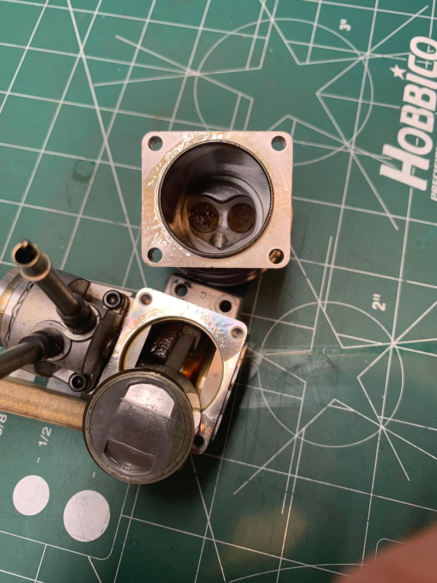
Well, I’m going to embark on my Saito 72 restoration. I recently purchased this used. Ad said it turns over smooth but it appears to have a seized bearing that spins on the crankshaft. 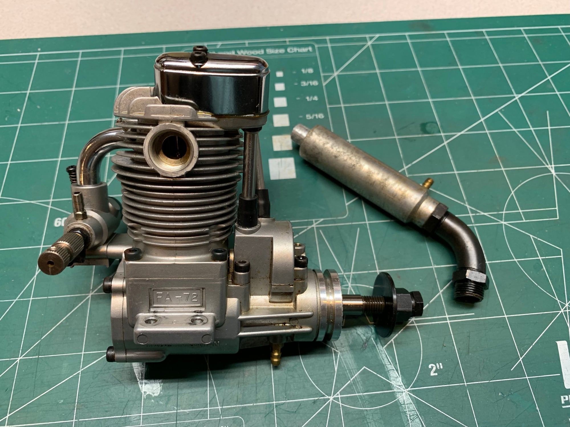
03-30-2019, 10:32 AM
The stuff we use is marked " high temperature".
i never looked for anything different.
When we want to get a rigid measurable impression, we often do a "Bondo Squeeze" ; coat everything with mold release and squeeze poly body filler into the gap.
Pops apart with a very faithful , rigid impression.
We also use the dentist type compound and silicones for flexible impression .
Need to check with the local foundry supply dealer.
03-30-2019, 10:33 AM
Saito fa72 crankshaft is SAI7223. Still available online.
Last edited by Glowgeek; 03-30-2019 at 10:37 AM.
03-30-2019, 11:08 AM
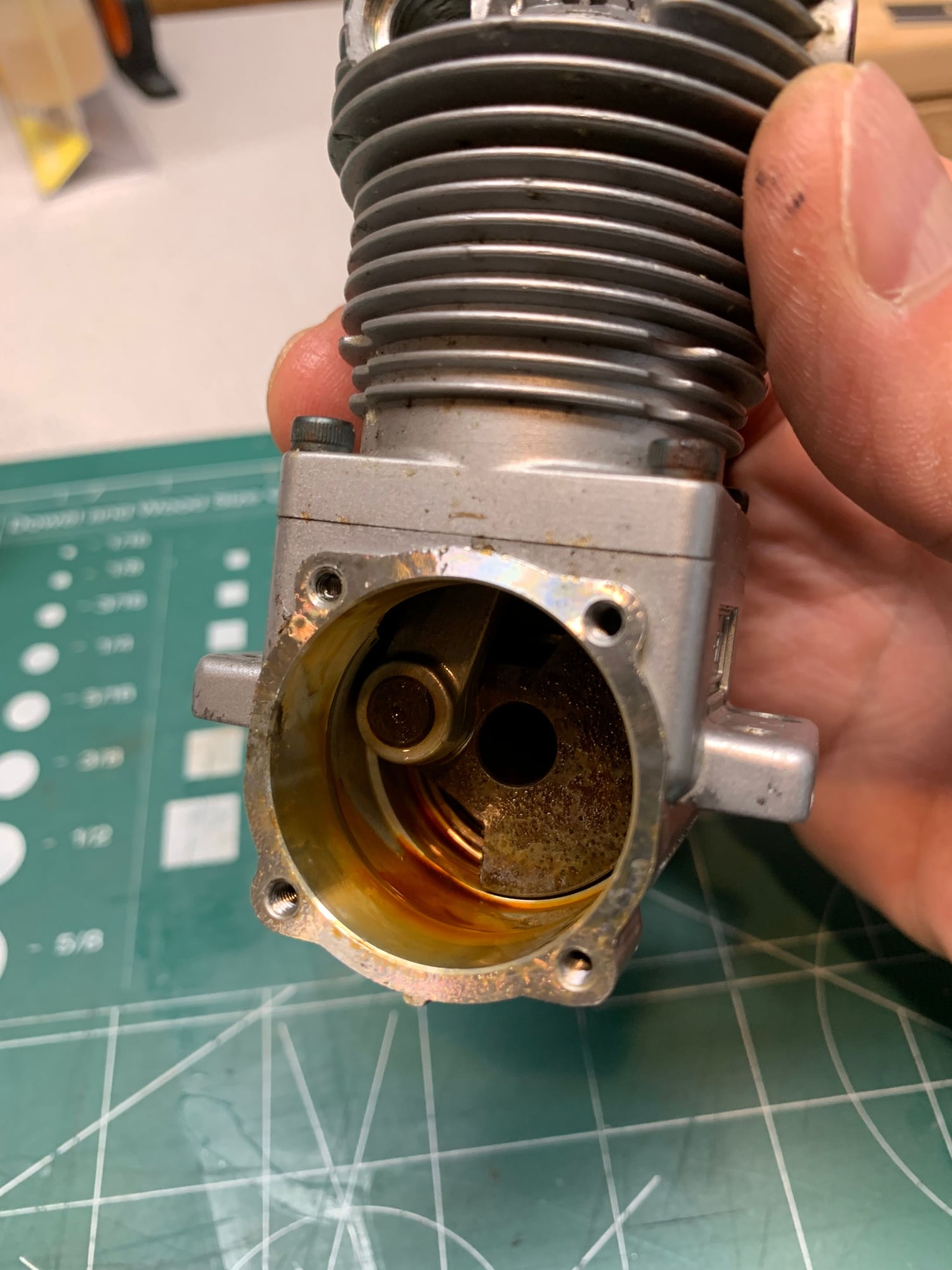
Thanks Glowgeek. It does indeed look lowtime. The valve adjustments look untouched. Piston and cylinder look pretty clean. I think the main bearing is a shielded bearing which made me think it was seized. The bearing does spin but not continuously. I still see some spin on the crankshaft. Since I have a new set of bearings I’m leaning towards replacing them. Or should I oil up the originals and run it as is?
03-30-2019, 11:37 AM
Thanks Glowgeek. It does indeed look lowtime. The valve adjustments look untouched. Piston and cylinder look pretty clean. I think the main bearing is a shielded bearing which made me think it was seized. The bearing does spin but not continuously. I still see some spin on the crankshaft. Since I have a new set of bearings I’m leaning towards replacing them. Or should I oil up the originals and run it as is?
A couple things. I wiped out the cam and lifters on my preowned 82 by running the bearings that came in it. In my case the crank had less rust nodules than yours appears to have but rust from the bearings got everywhere in the engine. Bearings are cheap insurance.
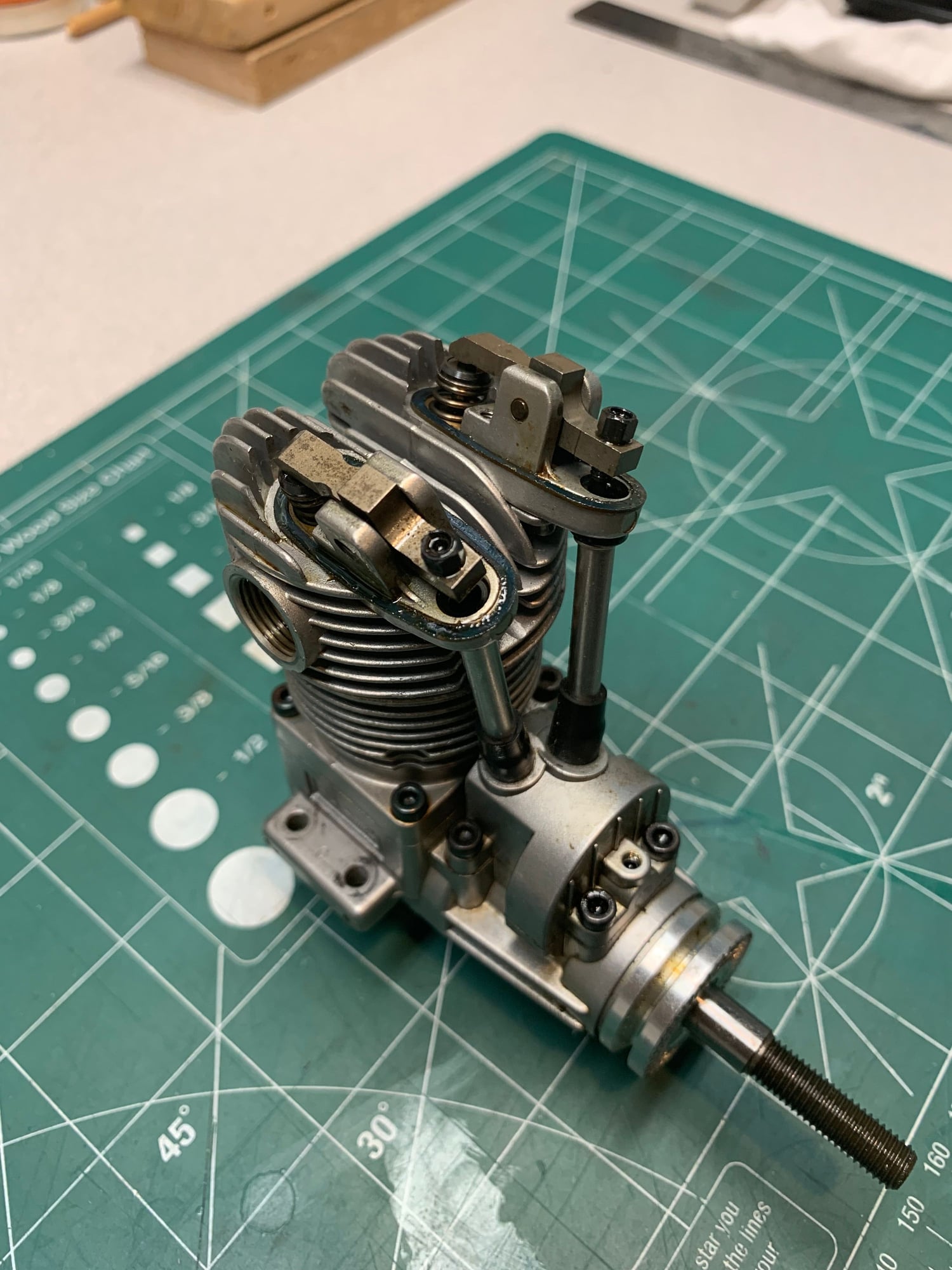
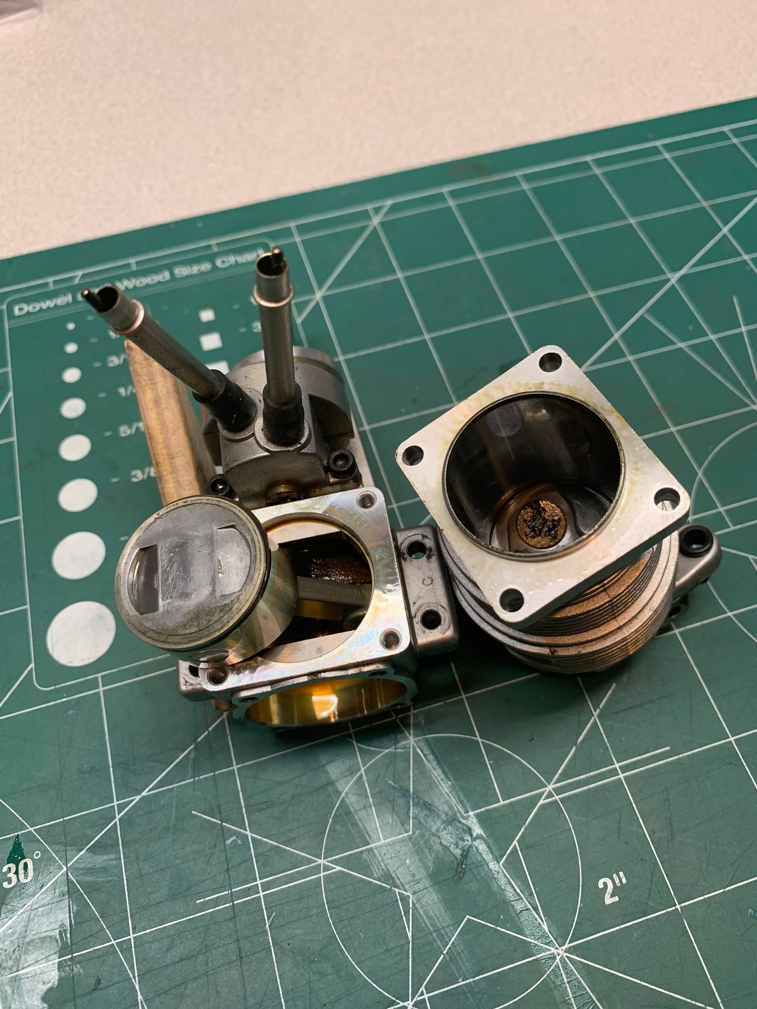
Completely disassemble every part of the engine and clean the parts Thouroughly.
Check the Cam for tappet dents. Check to see that the tappets will literally fall out of the tappet bores by inverting the cam gear housing. Clean the tappet bores with lacquer thinner and q-tips. Check the bottom of the tappets for beveling of edges. If the bevel has worn in more than 25% of the tappet diameter replace them.
Clean the int and exh valve stems with steel wool until they are bright and shiney all the way down to the valve caps. Use the smooth shank of a drill bit and laquer thinner to clean the valve guides. Don't clean the valve seats in the cylinders with anything besides a pencil eraser.
May seem like overkill to some but cleaning isn't expensive, parts are, and rust is THE saito killer.
Hint: It's a good idea to mark where the piston ring gap is located before completely removing the piston. I put a small scratch on the bottom of the cylinder to mark it. Reinstalling the ring gap in exactly the same location can sometimes lessen re-breakin time.
Last edited by Glowgeek; 03-30-2019 at 11:45 AM.
03-30-2019, 11:50 AM
OK. New bearings it is. I already have them, why not use them. All good advise Glowgeek. Thanks. I’m in it for a new gasket set too since the cam housing gasket got destroyed. Are those aftermarket sets on eBay any good?
03-30-2019, 11:53 AM
They're fine. You can make your own gasket out of paper stock. IIRC .0085" is the standard thickness for that gasket.
03-30-2019, 04:07 PM
I'm unsatisfied with my cc measurements for my 82. Even though I'm confident in my technique and fairly confident in the CR results, because that's a proportional calculation, it bugs me that the swept volume is so far off. Obviously Saito would have marketed the .82 as an .85 if that's what it was. I'm sure it's not.
Some internet research has revealed some interesting things. 1ml = 1cc, I didn't know that, but the aha moment came when I learned that 1cc of pure water should weigh 1 gram at 38.4°f. Well hallelujah, that gives me a way to check my 3cc syringe for accuracy! I just happen to have a jug of distilled water and a beam style powder scale graduated down to.1 grains. Should be a simple thing to find even a minute error in the syringe. Compensating for room temp (74°f) my 3cc syringe should deliver 46.161 grains (2.991 g) of pure water.
More later
03-30-2019, 04:17 PM
Senior Member
The stuff we use is marked " high temperature".
i never looked for anything different.
When we want to get a rigid measurable impression, we often do a "Bondo Squeeze" ; coat everything with mold release and squeeze poly body filler into the gap.
Pops apart with a very faithful , rigid impression.
We also use the dentist type compound and silicones for flexible impression .
Need to check with the local foundry supply dealer.
i never looked for anything different.
When we want to get a rigid measurable impression, we often do a "Bondo Squeeze" ; coat everything with mold release and squeeze poly body filler into the gap.
Pops apart with a very faithful , rigid impression.
We also use the dentist type compound and silicones for flexible impression .
Need to check with the local foundry supply dealer.
I scored my sheet wax way back when I worked at GM Indy Metal Fab. We stamped pick up truck door, truck bed side and tailgates skins etc.
A close friend was a pattern maker. The patterns they were waxing for metal thickness were stamping dies that had many compound curves at sharp inside outside radiused corners. The wax in question gets pliable at body temperature so it can be manipulated as it is hand rubbed over the dia patterns.
They were just transitioning from laminated wood patterns to some sort of rigid polymer product.
They also used 2 part epoxy type products to make castings. In that case the used PVA as a release agent
03-30-2019, 05:18 PM
Yep, that is the same type sheet wax we use. We do metal stampings. Been at it for over 50 years.
We buy our sheet wax at a large foundry supply house. Foundries use patterns. When I entered the trade, the patterns were usually wood, often woods like mahogany , cherry etc. Now we use synthetic resins and urethane foams for that purpose. In the old days mostly hand mill work, now CNC. That is the trade.
The cast epoxy is but one material. We have acrylics, urethane, silicones etc on hand as well.
Rapid prototype parts from a variety of materials.
Same uses that we employ, same company. Likely the same product
Last edited by Jesse Open; 03-30-2019 at 05:29 PM.
03-31-2019, 10:33 AM
A little update on syringe calibration and CC-ing an engine. It's been a learning experience for me if nothing else. Great care must be taken to calibrate the syringe for one. Secondly, no spilling allowed obviously. Although it is handy to mount up a degree wheel, which I did, it is not an absolute requirement because the oil level at the glow plug hole will rise and fall with the slightest rotation of the crank. It's easy to see 1° of rotation. What's NOT easy to see is where the syringe rubber plunger lines up with the syringe graduation marks. I ended up using a jeweler's visor for that.
My 3cc syringe is not 3.0 cc as indicated by the markings, it is actually 2.852 cc and that explains why my FA82 measured at 85 cc. I found the error through water density measurement (including density compensation for temp). If anyone is interested in exactly how I accomplished this just PM me.
FINAL NUMBERS:
Combustion Chamber Vol: 1.664 cc
Glow Plug Vol: 0285 cc
Swept Vol: 13.357 cc (81.51 cubic inches)
Compression Ratio: 8.893:1
Now I just need to make a jig to securely hold the case and it's off to the machine shop.
ADDING: Making a piston stop for finding perfect TDC takes less than 5 minutes using an old glow plug, #83 (.120") drill bit and a short piece of 1/8" brass rod.
Last edited by Glowgeek; 03-31-2019 at 10:50 AM.
03-31-2019, 12:21 PM
U
I can send you a lab grade, graduated glass Burrette tube.
A little update on syringe calibration and CC-ing an engine. It's been a learning experience for me if nothing else. Great care must be taken to calibrate the syringe for one. Secondly, no spilling allowed obviously. Although it is handy to mount up a degree wheel, which I did, it is not an absolute requirement because the oil level at the glow plug hole will rise and fall with the slightest rotation of the crank. It's easy to see 1° of rotation. What's NOT easy to see is where the syringe rubber plunger lines up with the syringe graduation marks. I ended up using a jeweler's visor for that.
My 3cc syringe is not 3.0 cc as indicated by the markings, it is actually 2.852 cc and that explains why my FA82 measured at 85 cc. I found the error through water density measurement (including density compensation for temp). If anyone is interested in exactly how I accomplished this just PM me.
FINAL NUMBERS:
Combustion Chamber Vol: 1.664 cc
Glow Plug Vol: 0285 cc
Swept Vol: 13.357 cc (81.51 cubic inches)
Compression Ratio: 8.893:1
Now I just need to make a jig to securely hold the case and it's off to the machine shop.
ADDING: Making a piston stop for finding perfect TDC takes less than 5 minutes using an old glow plug, #83 (.120") drill bit and a short piece of 1/8" brass rod.
My 3cc syringe is not 3.0 cc as indicated by the markings, it is actually 2.852 cc and that explains why my FA82 measured at 85 cc. I found the error through water density measurement (including density compensation for temp). If anyone is interested in exactly how I accomplished this just PM me.
FINAL NUMBERS:
Combustion Chamber Vol: 1.664 cc
Glow Plug Vol: 0285 cc
Swept Vol: 13.357 cc (81.51 cubic inches)
Compression Ratio: 8.893:1
Now I just need to make a jig to securely hold the case and it's off to the machine shop.
ADDING: Making a piston stop for finding perfect TDC takes less than 5 minutes using an old glow plug, #83 (.120") drill bit and a short piece of 1/8" brass rod.
03-31-2019, 01:37 PM
03-31-2019, 11:01 PM
My Feedback: (1)
hey guys, I am up late because I have to give my wife and son and daughter in-law a ride to the buss, they are just taking some time off for a trip,, well my my check out this engine I found on the U Tube, after you start the video see the first engine, but don't tell Pete about it I don't want to upset him or change his mind
Jim
Jim