


ground loops
 11-07-2020 | 05:13 PM
#26
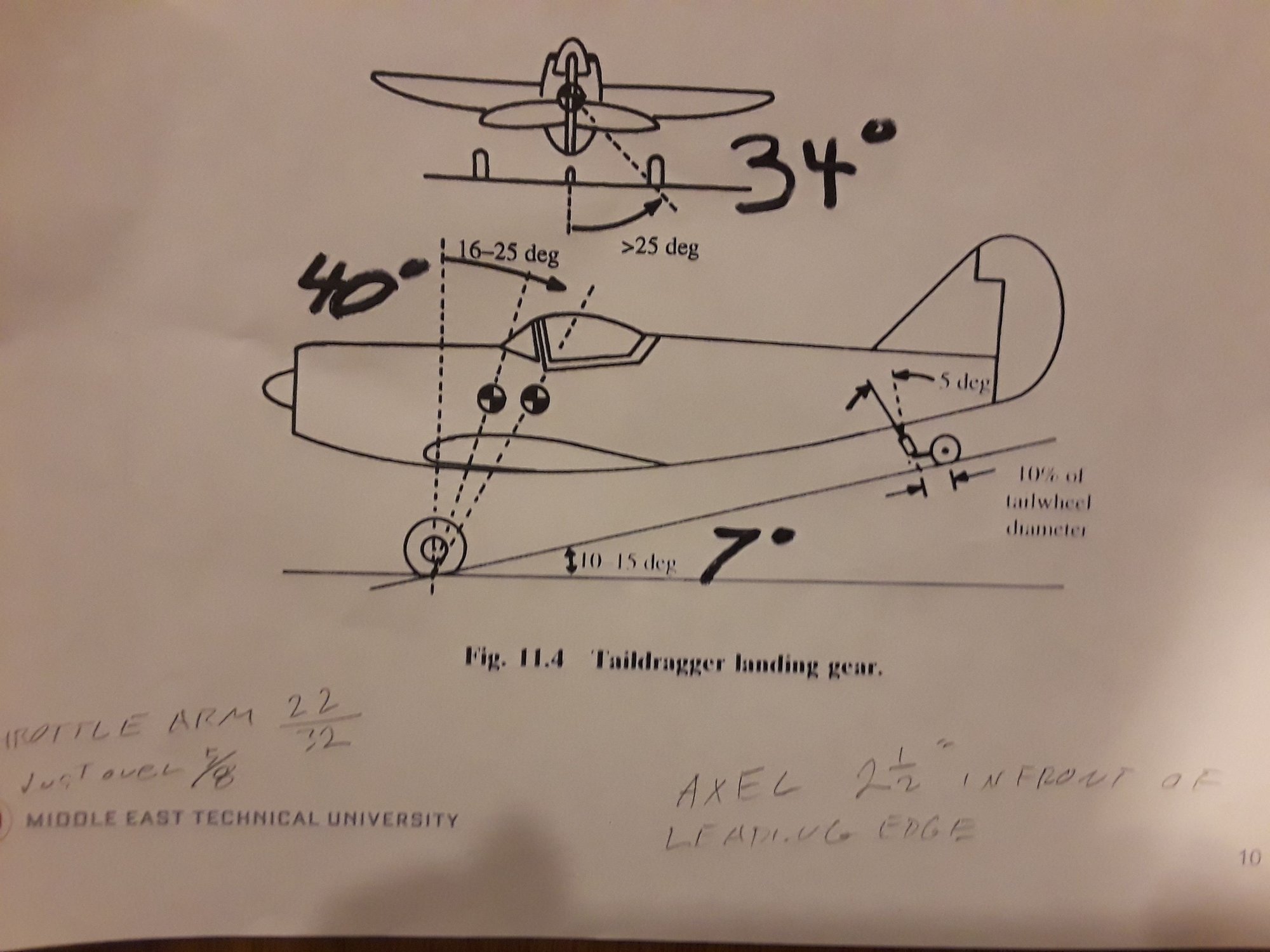
The professor shows the landing gear behind the leading edge of the wing . It will be possible to measure the angle from CG to axel. The question that will be hard to answer is where is the CG vertically. Based of the location of the battlers and balancing weight a good guess is about one third of the distance from the bottom of the wing to the top of the fuselage. Today has been a beautiful outdoor day filled with all of the activities it takes to care for 3 acres of plants and grass.
 11-08-2020 | 04:28 AM
#27

The professor shows the landing gear behind the leading edge of the wing . It will be possible to measure the angle from CG to axel. The question that will be hard to answer is where is the CG vertically. Based of the location of the battlers and balancing weight a good guess is about one third of the distance from the bottom of the wing to the top of the fuselage. Today has been a beautiful outdoor day filled with all of the activities it takes to care for 3 acres of plants and grass.
I echo the challenge of property maintenance. I've got a decent number of leaf dropping trees and two other pieces of property about 40 miles from here. So I get your challenge.
The following users liked this post:
Propworn (11-11-2020)
11-08-2020 | 07:15 PM
#28


My Feedback: (29)
There's no need for anybody to get offended. Several people have taken the time to share detailed explanations of causes for ground loops, and I'll bet the OP will be able to check them out and fix his plane. The fact is the problem could be a combination of more than 1 factor. We don't know sitting behind our keyboards. I appreciate everyone who tries to offer their knowledge and experience to help solve a problem whether they get it right on the first try or not.
Jester, I don't think anyone has been offended especially me. I'm just sharing some often overlooked practical knowledge that has been gained running Walbro equipped engines since 1997. I am however still interested in comparing throttle setup notes with Franklin. I'm most interested in how he achieves a nice linear throttle response without a throttle arm extension. If I can learn that perhaps I can save a couple hours work on each build.
11-09-2020 | 03:11 AM
#29

Jester, I don't think anyone has been offended especially me. I'm just sharing some often overlooked practical knowledge that has been gained running Walbro equipped engines since 1997. I am however still interested in comparing throttle setup notes with Franklin. I'm most interested in how he achieves a nice linear throttle response without a throttle arm extension. If I can learn that perhaps I can save a couple hours work on each build.
 A quick question here , don't all modern radios include a feature called "Throttle Curve" that allows setting actual throttle arm position VS TX throttle stick position to accommodate for the carb's non linear response ?
11-09-2020 | 04:30 AM
A quick question here , don't all modern radios include a feature called "Throttle Curve" that allows setting actual throttle arm position VS TX throttle stick position to accommodate for the carb's non linear response ?
11-09-2020 | 04:30 AM
#30

My Feedback: (2)
A FAR better solution is to set up a throttle linkage that will do the majority of this for you, THEN use a throttle curve for final trimming.
For our OP, I would add that when it comes to a plane that seems to be hard on it's landing gear, is the effect a forward CG has on a plane's ability to slow down while still maintaining good control (they won't!). The CG too far forward plane has a tendency to come in fast and use way too much runway - which invites trying to slow the plane down by dragging the gear in the grass. You can get away with flying like this on a .40 size plane, but when the planes start getting up into the teens for weight - this is a plan that doesn't work so well, regularly wiping out/removing the landing gear. Great Planes Super Sportsters were pretty well known for this. The factory "starting" CG shown in the manual was WAY too far forward (2"?), and when guys coming up through the ranks of smaller to bigger planes tried flying one of these 15-16 lb planes while still used to their .40-.60 size rigs, they had a terrible time - until somebody pointed out the CG issue. The plane was easily capable of tail wheel first landings regularly when set up correctly....
Last edited by ahicks; 11-09-2020 at 04:46 AM.
11-09-2020 | 05:24 AM
#31
My Feedback: (29)
Yea, as Al has stated most do. The secondary issue with these carbs and their short arms is resolution. I don't like throwing analogies out there but imagine at first driving a high power car in the snow with only 1/2" of petal travel. Now take the same situation and give the petal more travel ( throttle curve ) but you now have 6 spikes in power due to low resolution. Now set up that car with 3" of petal travel and an infinitely proportional power delivery. Don't anyone take this as me being irritated because I'm not, simply putting free information out there that took me years to learn. If people choose not to follow the advise then I just move on to helping the next guy. That said, I beleive between the video I posted of my 150cc Extra and the take off scores with my electric pattern airplane that my methods work. I do however find it funny that a couple guys from the AMA forum are questioning this. Perhaps it's because there isn't much of an audience there lately?
Once again, patiently waiting to learn how Franklin sets up his gas engine throttle.
11-09-2020 | 09:32 AM
#32
Yea, as Al has stated most do. The secondary issue with these carbs and their short arms is resolution. I don't like throwing analogies out there but imagine at first driving a high power car in the snow with only 1/2" of petal travel. Now take the same situation and give the petal more travel ( throttle curve ) but you now have 6 spikes in power due to low resolution. Now set up that car with 3" of petal travel and an infinitely proportional power delivery. Don't anyone take this as me being irritated because I'm not, simply putting free information out there that took me years to learn. If people choose not to follow the advise then I just move on to helping the next guy. That said, I beleive between the video I posted of my 150cc Extra and the take off scores with my electric pattern airplane that my methods work. I do however find it funny that a couple guys from the AMA forum are questioning this. Perhaps it's because there isn't much of an audience there lately?
Once again, patiently waiting to learn how Franklin sets up his gas engine throttle.
Once again, patiently waiting to learn how Franklin sets up his gas engine throttle.
 11-09-2020 | 09:40 AM
#33
My Feedback: (29)
That's just the point I am attempting to make, the TX throttle curve does not fix the issue. To remove the spike in the torque/power curve that all of these Walbro equipped engines have, you must extend the throttle arm. The throttle should be looked upon the same as any other control on the airplane.
11-09-2020 | 09:51 AM
#34
Just to get some more input, my friend who has been flying gas since gas engines came out tried to fly my airplane. He has three tail draggers that he brings to the field, a bipe with twin cylinder 60cc and two others in the 50 , 60 cc range. He pushed the throttle forward, the plane rolled forward about 8 feet and did a 180 degree right turn. He looked at me with an expression of pure surprise on his face. Never had that happen before.
In order to get the plane in the air I must be very gentle on the throttle. The plane is unstable and dances down the runway until it lifts off. At this point it has just enough power to fly, going immediately to full throttle gives a gentle left turn easy to correct with the rudder. All of this points to a landing gear problem. or perhaps CG. Landings are smooth and well behaved. Taxing back to the pit is a challenge. It will switch back and forth as to which way it wants to go. Next three days will be rain and wind, time to make some measurements..
I am not ignoring any of the suggestions. At the age of 81, I have 2 acres of grounds and five rental properties to look after. along with a small tree farm, and this is the busy season.
Jerry
11-09-2020 | 12:13 PM
#36
That last description sounds like a gear setup issue. I mentioned above a plane I had once where the gear and rudder had different neutral positions. That'll have you wagging your tail on the runway for sure. It also sounds like you might have some toe out if it's just plain squirrely like you describe. Another possibility is simply a too narrow stance, which exacerbates any other problems.
11-09-2020 | 04:26 PM
#37
Looks like the rain will start tomorrow and last for three days according to the weather man. Should be time to get some measurements and pictures.
11-10-2020 | 06:38 AM
#38
I got a Cub several years ago that was already used and abused. It was darn near impossible to take off without just slamming the throttle and trying to make corrections until it was up. I took the wheels off and put a straight edge across both axles. They were off from each other and also off from the centerline. I spent some time with a couple pairs of channel locks getting the axles both perpendicular to the centerline of the plane, then got the tailwheel adjusted to roll straight. Since then, it has a straight roll with no tendency to yaw when the tailwheel lifts, then a slight and very predictable left turn tendency as I rotate to takeoff. The time spent getting the gear perfectly straight was well worth it.
11-11-2020 | 03:52 AM
#39
...Why is all this important? Because what we see is that every force on the aircraft at this point would predict a nose LEFT yaw as the engine speed increases, the aircraft starts rolling, and the nose pitches down. However, your aircraft is demonstrating the opposite behavior. So where to start?
Check the amount of right thrust built in?
Under static conditions, is the tail wheel parallel to the aircraft longitudinal axis (emphasis added)?
Under static conditions, are the main wheels parallel to the aircraft longitudinal axis?
Do these remain parallel under dynamic conditions? (i.e. no struts bend under loads as throttle comes up) (emphasis added)
Is the angle from the aircraft CG through the main wheel axles approximately 15 degrees forward of vertical axis per recommendation in note 3?
Is tail-wheel direction parallel with the longitudinal axis when rudder is neutral (emphasis added)?
Does the tail wheel stay aligned with the rudder under load (emphasis added)?
Check control surface rigging. For example, is there some built in right yaw input (tailwheel or rudder)?
Last edited by franklin_m; 11-11-2020 at 04:21 AM.
11-11-2020 | 05:18 AM
#40
My Feedback: (29)
Perhaps if you bothered to read my first post more carefully:
Keep in mind that this assumes that both your wheels rotate freely and don't have any weird angles. Don't buy into the toe in or tie out stuff, it makes no difference on our models.
It's a real shame that you have used this thread to grind your axe with me. The OP created this thread on hopes to get some real help, not for you to satisfy your need to " Even the score " because you still think that I am responsible for getting you banned from the other site. Why not tell him the truth and admit that you have never run a gas engine let alone had to deal with a situation such as he describes and your only reason for being in this thread was to be a pebble in my shoe. Fairly obvious considering the wording used in your posts.
11-11-2020 | 03:20 PM
#41
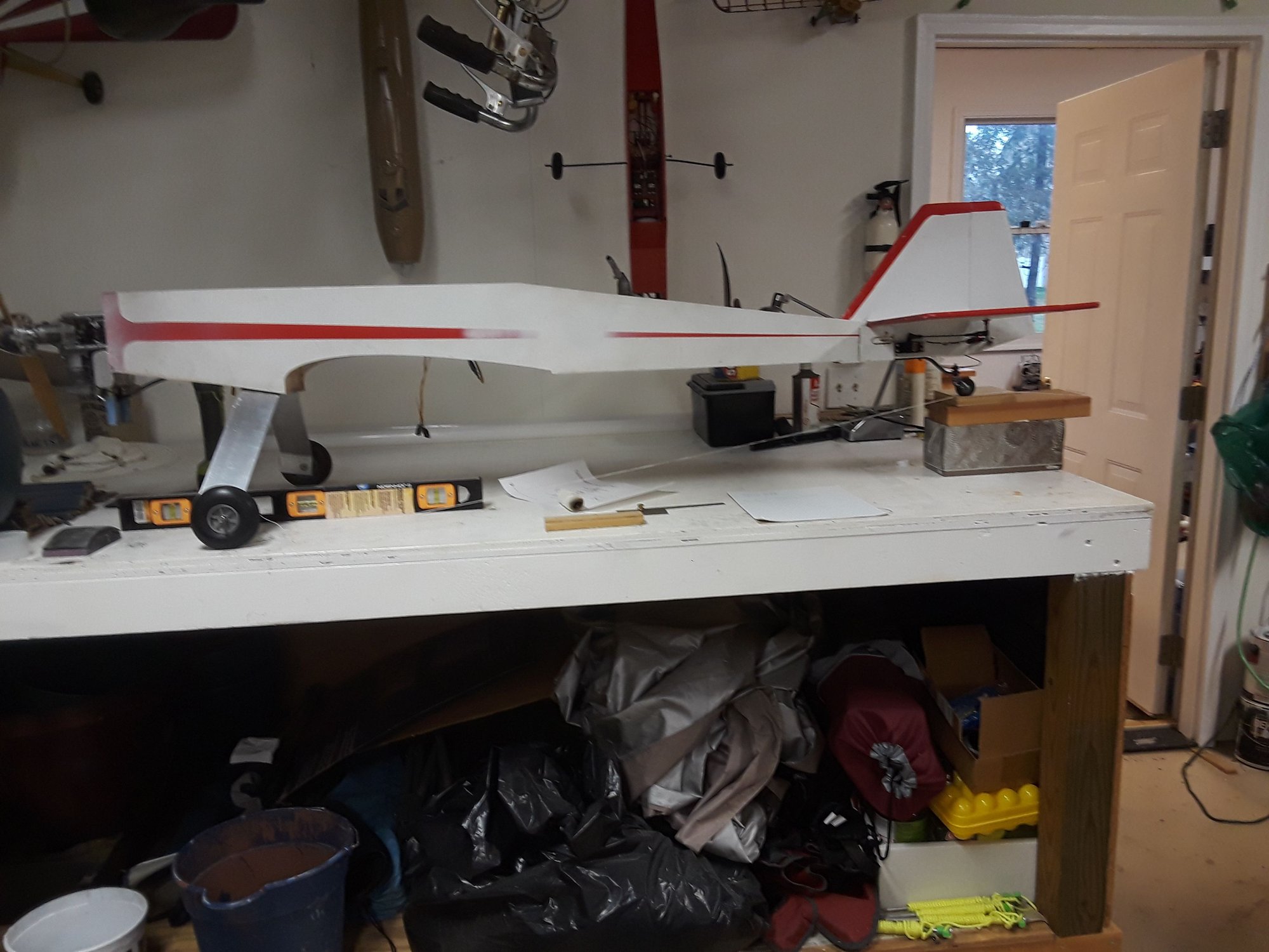
low wing stick level on table
These are the measurements
The original method used to measure the distance of axel to leading edge of wing was incorrect. It is 2.5 inches in front of wing.
There have been three different tail wheel assemblies on this airplane. The current one is probable worst case.
The servo arm and the throttle arm are the same length Just over 5/8 of an inch.
11-11-2020 | 05:34 PM
#42
My Feedback: (29)
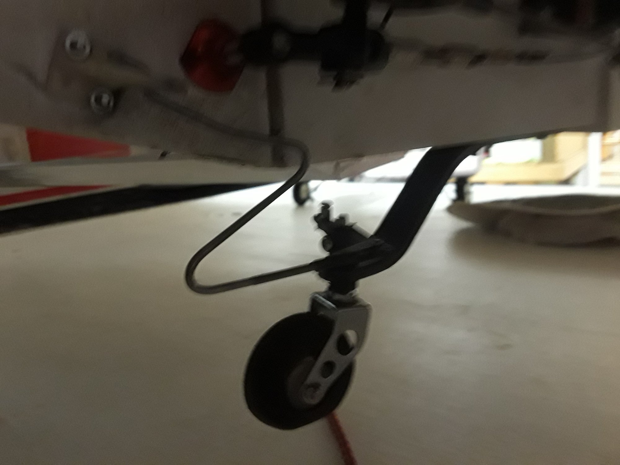
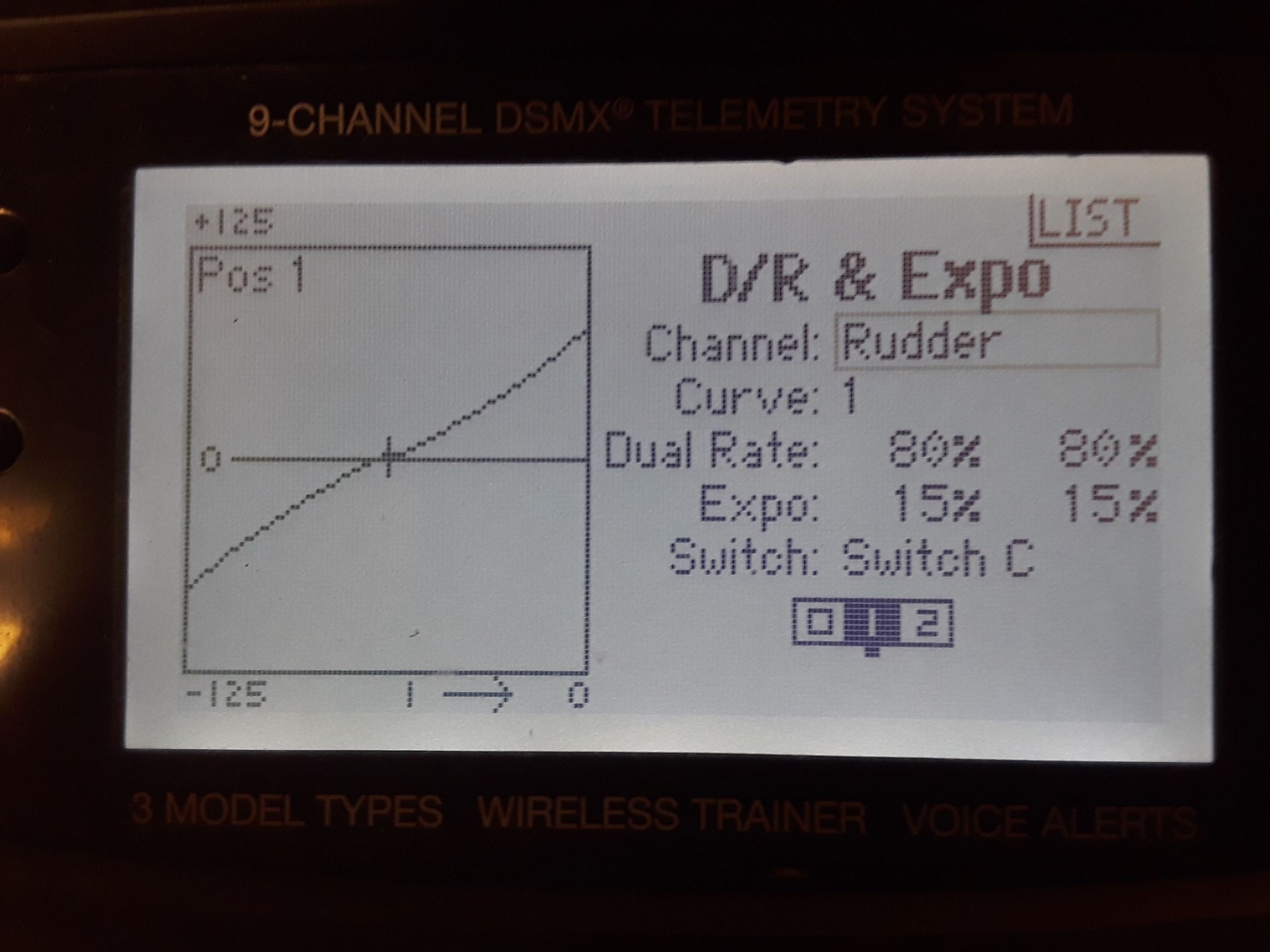
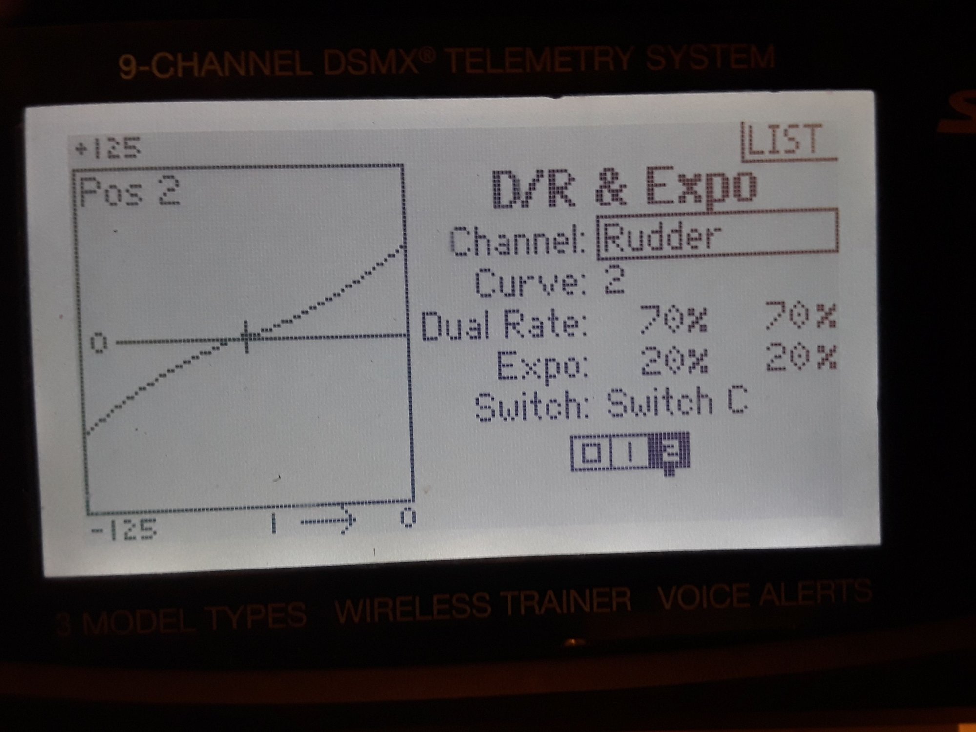
The main gear is a bit far forward, not terrible though. I can't get a very good view of your tailwheel linkage, perhaps a closeup of that would help. Things I would still like to know: how much rudder throw are you running? How much expo on rudder? What wing cord percentage is the CG?. It would also help if you took a picture of the nose from the top.
Your throttle linkage is a 1:1 ratio between servo arm and throttle arm. The throttle arm only needs to move around 40 degrees to go from idle to 85% opening. With your throttle travel volumes set to 100 the servo should have close to 90 degrees of travel. That is more then double of what you need. My suspicion is that you have your throttle volumes set to 50% or less which effectively cuts your resolution in half. Even worse you could have a large gap in values between high and low. Could you look and see what your throttle travel volumes for high and low are and let me know please? A few pictures of my own. As you can see the gear on my 1/3 scale Reed Falcon are a bit on the forward side as well. Also pictured is the throttle arm on the 70cc twin. Another picture shows where the travel volumes are adjusted to. I do a throttle curve that somewhat acts as expo to soften throttle response around center.
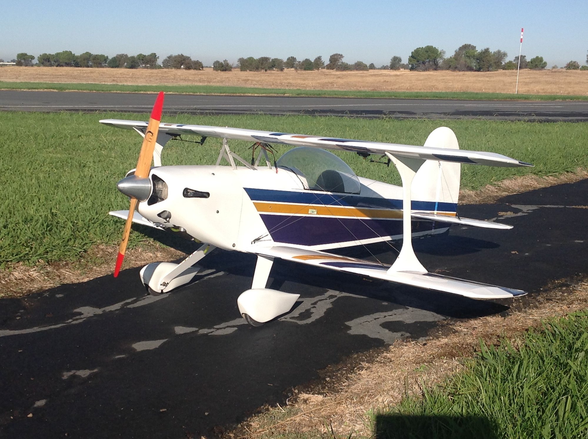
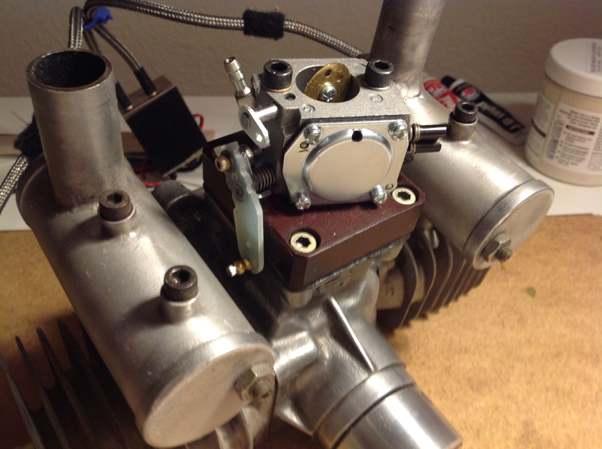
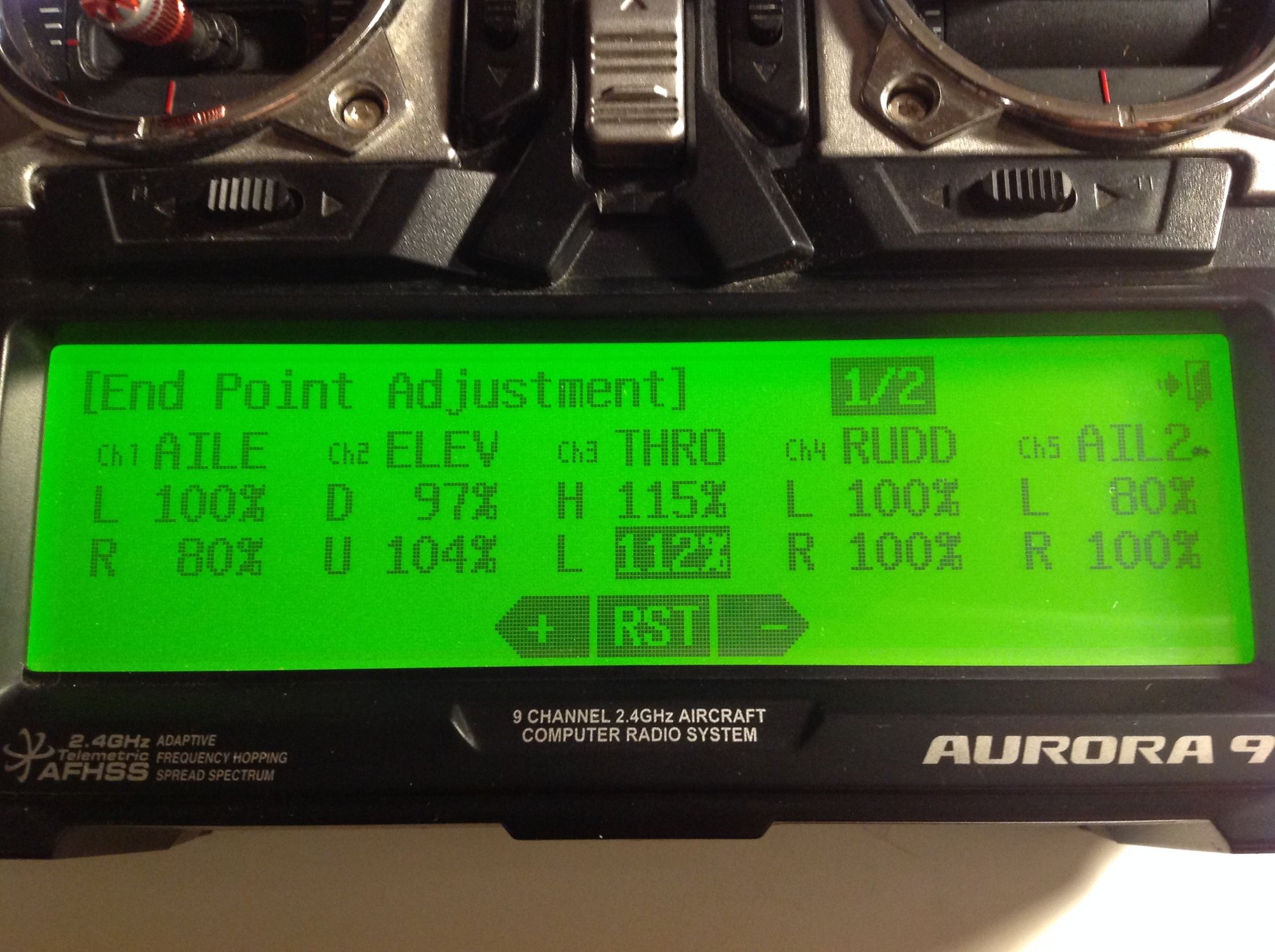
Your throttle linkage is a 1:1 ratio between servo arm and throttle arm. The throttle arm only needs to move around 40 degrees to go from idle to 85% opening. With your throttle travel volumes set to 100 the servo should have close to 90 degrees of travel. That is more then double of what you need. My suspicion is that you have your throttle volumes set to 50% or less which effectively cuts your resolution in half. Even worse you could have a large gap in values between high and low. Could you look and see what your throttle travel volumes for high and low are and let me know please? A few pictures of my own. As you can see the gear on my 1/3 scale Reed Falcon are a bit on the forward side as well. Also pictured is the throttle arm on the 70cc twin. Another picture shows where the travel volumes are adjusted to. I do a throttle curve that somewhat acts as expo to soften throttle response around center.
11-13-2020 | 07:42 AM
#43
The tail wheel pictured is the current and forth iteration of assemblies. Tail wheels with soft springs, hard springs, two springs on each side, no springs and no tailwheel just a slide. This one is a hard connection. The wheel has a flat spot from being slid sideways. Holding up elevator to keep the tail wheel in contact with the ground does no good, It just wipes the tire right off the rim.
 11-13-2020 | 08:20 AM
#45
The cg is 5" from leading edge of wing. Cord is 18". The CG is marked on the fuselage but it did not show up in the image.
The throttle curve softens the low end more than the middle. The servo moves 90*.
Throttle closed to fully open is 90*.
2 1/2 " axel forward of leading edge of wing does not seem good. The next time I go to the field a more aggressive throttle curve and another landing gear will be used.
Jerry
The throttle curve softens the low end more than the middle. The servo moves 90*.
Throttle closed to fully open is 90*.
2 1/2 " axel forward of leading edge of wing does not seem good. The next time I go to the field a more aggressive throttle curve and another landing gear will be used.
Jerry
11-13-2020 | 01:36 PM
#46
My Feedback: (29)
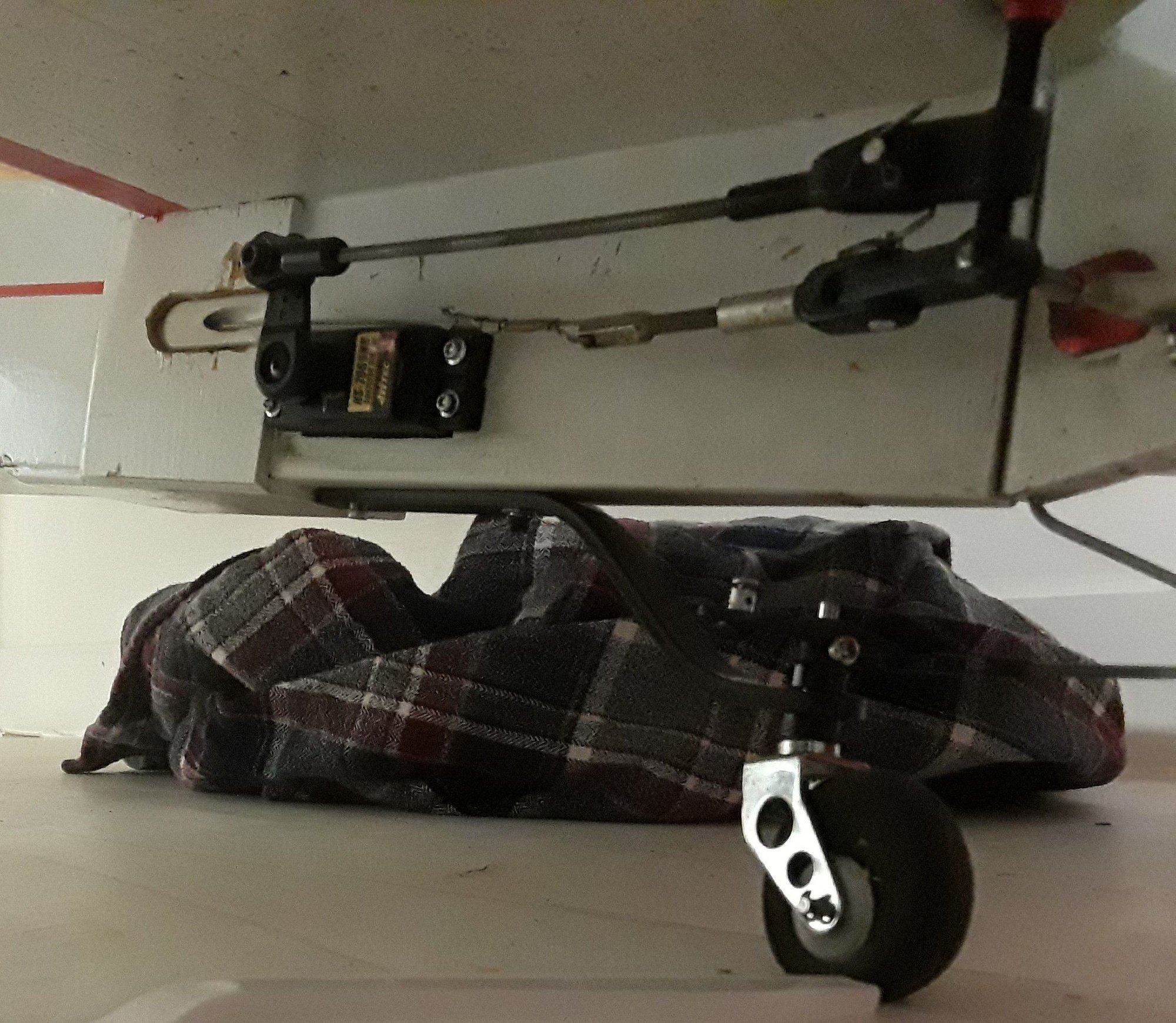
I see a bunch of issues with those pictures. First off your rudder pull pull cables are slack. This means that around center stick you have zero rudder/tailwheel control. This is going to setup a time delay of when you actually get some result from Stick movement. Part of why you have that situation is that it appears in the picture your rudder horn pivot point is well in front of your hinge line. If this is the case you may have loosened the cables at center to keep them from being puller overly tight due to the offset between the hinge line and the horn pivots. Ideally on a pull pull setup the clevis hole in the control horn would line up with the hinge line. Then the servo arm and control horns would be the same width but not absolutely nessesary. This would really help in keeping the cables tight throughout the entire movement.
The next item is probably more of an issue. You can't run a hard single linkage on a tailwheel like you have. The tailwheel strut will flex and that in return will create a directional input. If you look at your picture, the wheel looks straight. When the airplane is at rest with some weight on the tailwheel the strut will flex up and introduce a right input. Holding up elevator with airflow over the tail ( taxi and take off ) and you will be applying more downforce which will input even more right input. My suggestions going forward is to sort out your pull pull cables or move your rudder servo to the tail as your CG is currently very conservatively forward. Then fabricate a tiller arm shaped like a T and install as per the drawing. Those alone will go a long ways to solve your issue. For a complete fix, moving the wheel axles back some either with a new gear or by installing a wedge between the gear and fuselage and my throttle linkage fix. IMO 1:1 servo/throttle ratio is still far from ideal.
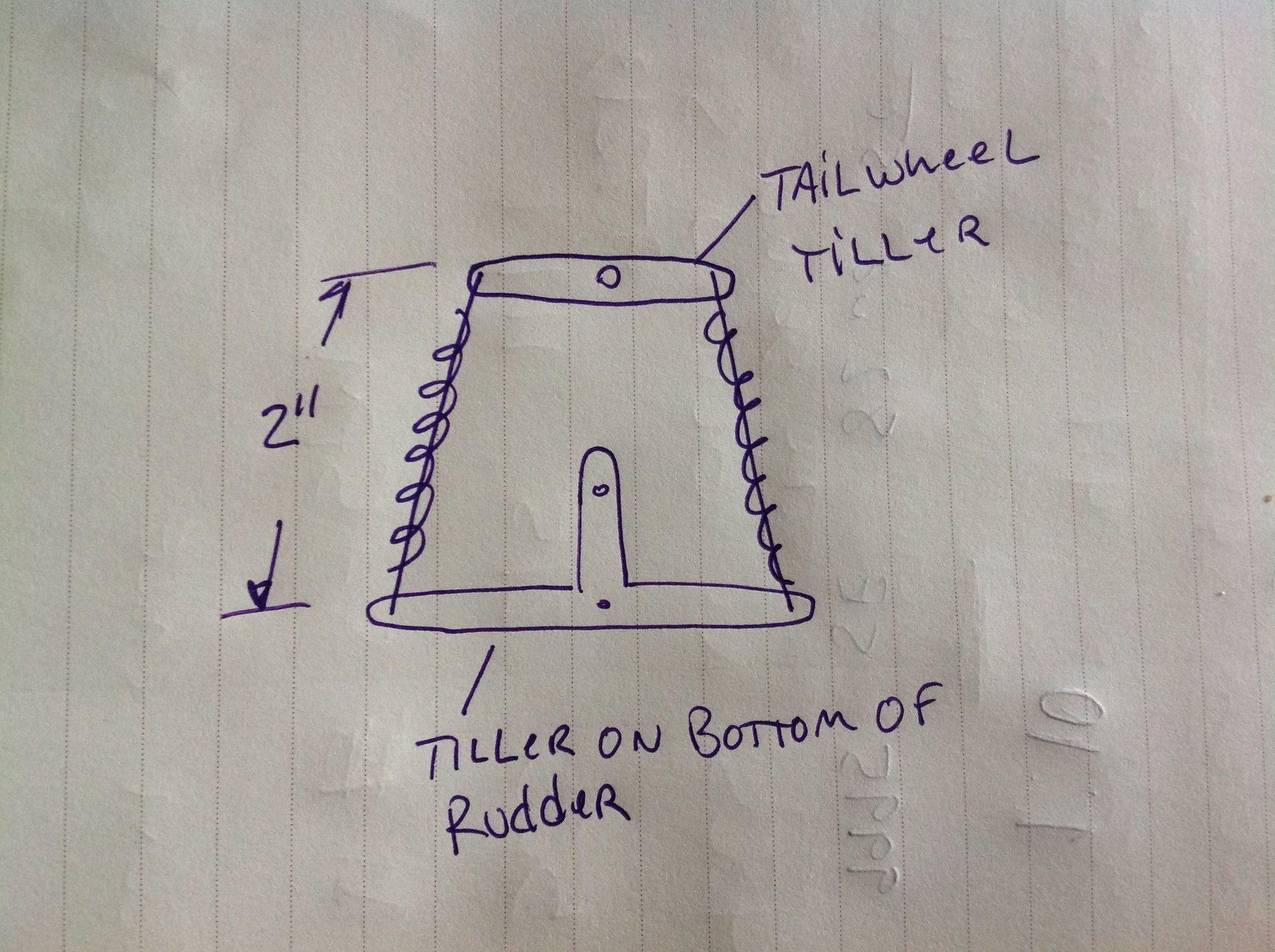
The next item is probably more of an issue. You can't run a hard single linkage on a tailwheel like you have. The tailwheel strut will flex and that in return will create a directional input. If you look at your picture, the wheel looks straight. When the airplane is at rest with some weight on the tailwheel the strut will flex up and introduce a right input. Holding up elevator with airflow over the tail ( taxi and take off ) and you will be applying more downforce which will input even more right input. My suggestions going forward is to sort out your pull pull cables or move your rudder servo to the tail as your CG is currently very conservatively forward. Then fabricate a tiller arm shaped like a T and install as per the drawing. Those alone will go a long ways to solve your issue. For a complete fix, moving the wheel axles back some either with a new gear or by installing a wedge between the gear and fuselage and my throttle linkage fix. IMO 1:1 servo/throttle ratio is still far from ideal.


