


how to hinge a thick aileron?
 01-09-2014 | 04:56 PM
#1
Thread Starter
Junior Member
Joined: Mar 2007
Posts: 8
Likes: 0
Received 0 Likes
on
0 Posts
From: Iowa,
IA
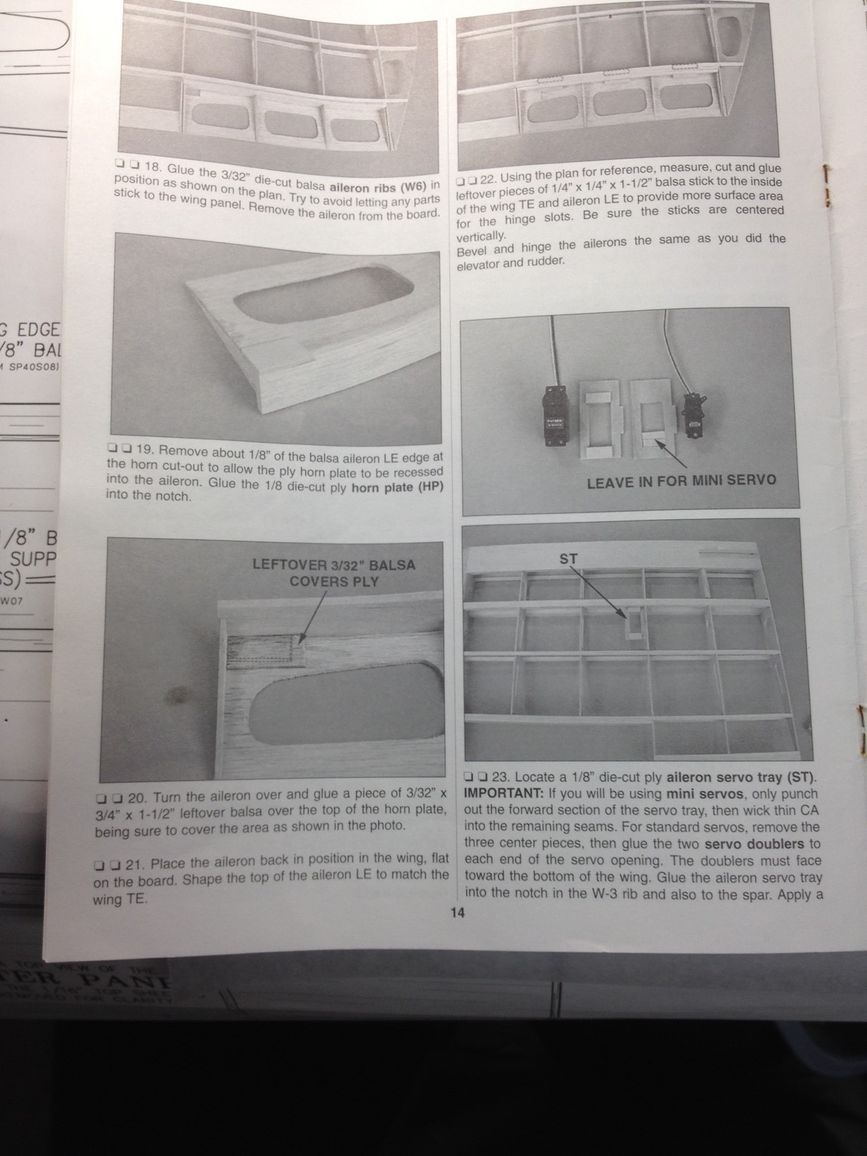
I am building a Great Planes Slow Poke Sport 40, and have a question about how to bevel and hinge the ailerons. The instructions state to "bevel and hinge ailerons as you did the elevator and rudder" (using CA hinges). The rudder and elevator leading edges were easy to bevel as they were stick built. The plans call for 1 inch aileron deflection or throw in each direction. Looking at the pictures, I am not sure I have enough material to bevel an aileron that is about 3/4 inch thick at the leading edge. I could add 3/4 inch tri-stock to the aileron leading edge, but then the aileron trailing edge would not be flush with the wing trailing edge. Any ideas?
Thanks
Thanks
 01-10-2014 | 03:54 AM
#2

I haven't built Slow Poke, but I have built several models with a similar aileron design. I say similar, because in this type of aileron, the leading edge is built at an angle, with the hinges placed near the top.
I agree with you. There isn't enough material to bevel the ailerons as built.
Let's see if somebody, who has built this model can offer some insight. If not, let me know. I have some ideas.
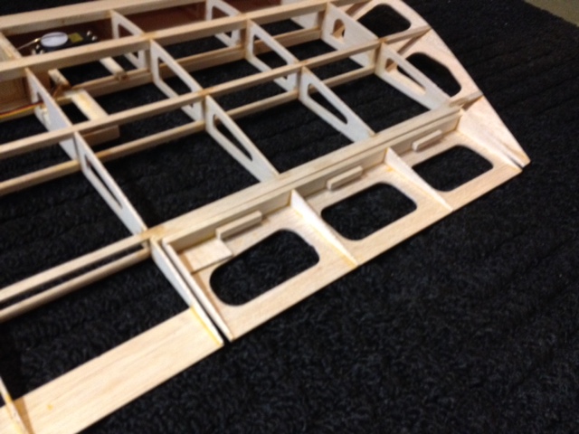
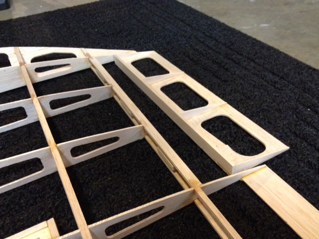
Here are some pics that illustrate how I build this type of aileron. The pics are from two different models, but the construction is basically the same. Notice that the aeleron's ribs are angled, where the leading edge is attached.
Where in Iowa do you live ? I used to live in the Cedar Rapids/Marion area.
I agree with you. There isn't enough material to bevel the ailerons as built.
Let's see if somebody, who has built this model can offer some insight. If not, let me know. I have some ideas.
Here are some pics that illustrate how I build this type of aileron. The pics are from two different models, but the construction is basically the same. Notice that the aeleron's ribs are angled, where the leading edge is attached.
Where in Iowa do you live ? I used to live in the Cedar Rapids/Marion area.
Last edited by TomCrump; 01-10-2014 at 04:00 AM.
01-10-2014 | 06:38 AM
#3
Senior Member
Joined: Jan 2011
Posts: 2,018
Likes: 0
Received 0 Likes
on
0 Posts
From: SorrentoBritish Columbia, CANADA
I am building a Slow Poke and the plans show to bevel the aileron with the hinge in the center . You need to add some extra backing for the hinge . An alternative way would be to hinge at the top and bevel as Tom suggested .. I prefer this way myself and am going to do that with mine . I think it might help in the turns .. I am going to use hinge points also . I find them easier to install than CA hinges .
01-10-2014 | 07:05 AM
#5


My Feedback: (1)
Yes for me on any airplane like that with really thick ailerons it always seems best to simply raise the hingeline near the top surface. If you like you can with what ever kind of hinge cut your hinge slots from near the top surface angled downward at a slight angle. This will give a little more meat on both sides of the hinge.
Another advantage is by hingeing near the top surface there will be no visable big gap from the beveling, All of that gap will now be on the bottom of the wing
John
Another advantage is by hingeing near the top surface there will be no visable big gap from the beveling, All of that gap will now be on the bottom of the wing
John
01-10-2014 | 07:09 AM
#6
Thread Starter
Junior Member
Joined: Mar 2007
Posts: 8
Likes: 0
Received 0 Likes
on
0 Posts
From: Iowa,
IA
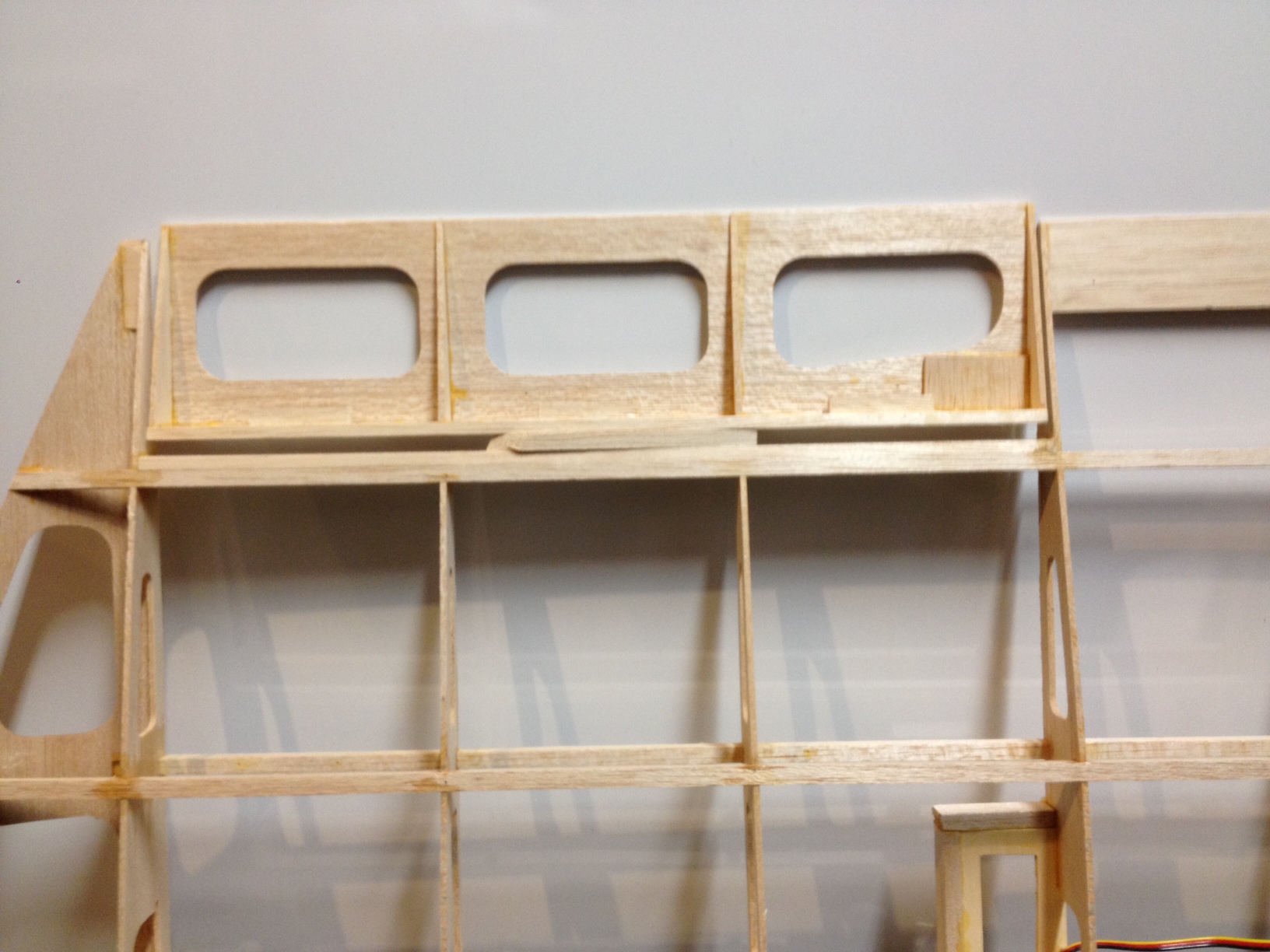
Thanks for the advice. I believe I have built the ailerons according to the plans and have added additional material for the CA hinges (1/4x1/4x 1.5 inch blocks) both on the aileron leading edge and the wing trailing edge. The plans call for hinging in the middle of the aileron but I am open to modifications or using robart hinges if that is best. I am guessing that if I add material to bevel I would need to add either thick tri stock or at least 1/4" balsa plank and then bevel to get a 1 inch deflection. I have never used a top hinge but am open to suggestions.
01-10-2014 | 07:45 AM
#7
Senior Member
Joined: Jan 2011
Posts: 2,018
Likes: 0
Received 0 Likes
on
0 Posts
From: SorrentoBritish Columbia, CANADA
It looks like it ,yes I think the ailerons are built to the plans. Its not to late to change them though . I haven't built mine yet. I am just getting ready .. I am just finishing up a Top Flight Elder Kit .. I have read over the plans several times and searched it on the net ..It looks fairly straight forward . Its a chubby little thing . I am just at the point where I am reading everything I can find that anybody has posted about it .How to build , how to fly , etc. .
01-10-2014 | 08:59 AM
#8

My Feedback: (11)
If your kit has the proper-thickness parts in it, and you build it according to the plans and instructions, you will find that you will have plenty of control surface travel. It was properly-executed during the design and production process. However, if the parts are not correct, or the resultant assembly has difficulties, then all bets are off.
01-10-2014 | 01:45 PM
#9
Senior Member
Built up ailerons usually will have the bevel built into them before capping the leading edge, then the hinges are installed right close to the top, are you sure you didn't miss that step just before capping off the leading edge?
01-10-2014 | 05:51 PM
#10
Thread Starter
Junior Member
Joined: Mar 2007
Posts: 8
Likes: 0
Received 0 Likes
on
0 Posts
From: Iowa,
IA
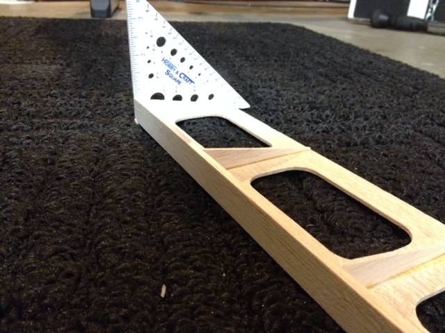
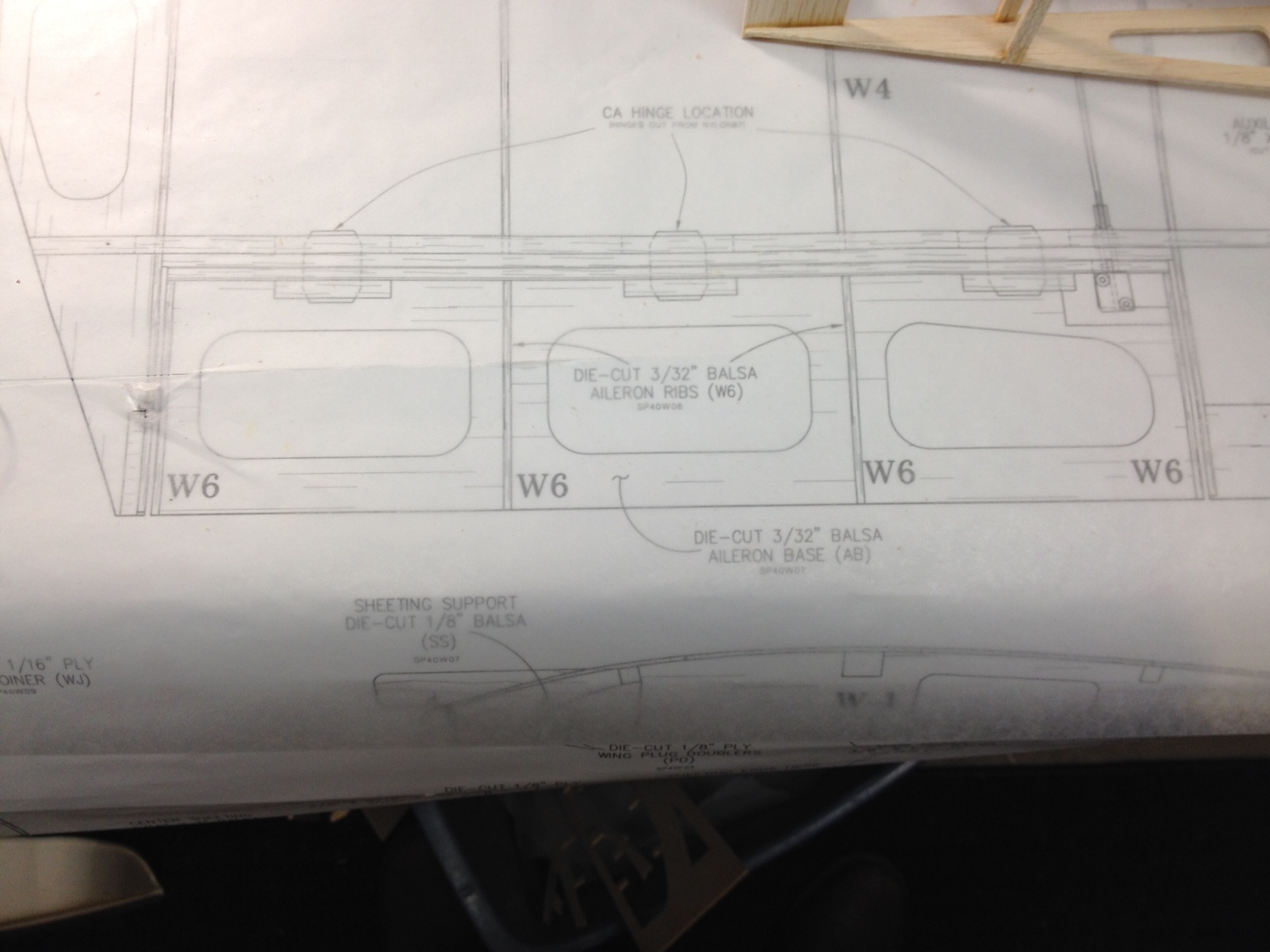
Thanks for all the advice. I don't think I have missed any steps and my aileron looks just like the plans and manual, although neither shows the beveled aileron leading edge.
Here is a picture of the plans and instruction manual. I am still puzzled how this should be beveled and hinged without changing the shape of the aileron significantly.
Any ideas on which if these types of hinges anyone would recommend?


Here is a picture of the plans and instruction manual. I am still puzzled how this should be beveled and hinged without changing the shape of the aileron significantly.
Any ideas on which if these types of hinges anyone would recommend?
01-10-2014 | 06:12 PM
#11

Looks like the plan was not well thought out as there is not enough material to bevel the leading edge of the aileron. You could add a wedge shaped piece of balsa you cut out to add the bevel on the leading edge and top hinge, but then the aileron would not be flush at the trailing edge with the wing. Might be your only option.
01-11-2014 | 02:43 AM
#13
At this point, if it were me, I would draw a line down the center of the length of the leading edge. I'd use a sanding bar and bevel the LE, leaving the line as the pivot point.
The aileron looks to be built per instructions, and Bax states that it will provide enough aileron movement.
If it doesn't, lispro can cut off the leading edge, and modify his ailerons to mimic the construction of those that I posted above, or follow your suggestion.
Your way may be a little easier than mine.
01-11-2014 | 05:44 AM
#14
Senior Member
Joined: Jan 2011
Posts: 2,018
Likes: 0
Received 0 Likes
on
0 Posts
From: SorrentoBritish Columbia, CANADA
In lispros pics the one called top hinged aileron is how I would do it . I would use hinge pins , I make up a jig to drill the hinge holes because they are difficult to do accurately
01-11-2014 | 06:02 AM
#15
01-11-2014 | 07:09 AM
#16
Senior Member
Looking at the plans it appears the leading aileron cap is double thickness, there actually is enough to make a bevel, we're only looking for what, maybe 5/8 travel? not 3-D rates, it doesn't take much.
01-11-2014 | 03:08 PM
#18
Senior Member
My Feedback: (5)
For top hinging, on these ailerons, I would use Dubro flat pinned hinges. The Robart hinge points have a certain degree of difficulty in installing them properly in this application. http://www3.towerhobbies.com/cgi-bin...?&I=LXD941&P=0
At this point, if it were me, I would draw a line down the center of the length of the leading edge. I'd use a sanding bar and bevel the LE, leaving the line as the pivot point.
The aileron looks to be built per instructions, and Bax states that it will provide enough aileron movement.
If it doesn't, lispro can cut off the leading edge, and modify his ailerons to mimic the construction of those that I posted above, or follow your suggestion.
Your way may be a little easier than mine.
 01-11-2014 | 04:15 PM
#20

LISPRO Draw a line thru the center of the front of the 3/4" leading edge from side to side. Now slot your holes for CA hinges into the line & thru the 3/4" leading edge & into your 1/4" backup wood. Now either sand from the top of the aileron to the center line you previously drew & flip it over & do the same from the bottom of the aileron. Or use a knife to shave off the same from both sides & finish sand in your bevel. You'll find you will have plenty of aileron throw. Try it on a scrap piece first if you want.......Gene
01-11-2014 | 07:16 PM
#21
Thread Starter
Junior Member
Joined: Mar 2007
Posts: 8
Likes: 0
Received 0 Likes
on
0 Posts
From: Iowa,
IA
Thanks for all the advice. Sounds like my options are to sand/shave the existing leading edge of the aileron to bevel in the middle for the hinge per plans, or to add material and could do either a top hinge or traditional middle hinge. (for middle hinge I might use the CA hinges, for top hinge I could use the Dubro pinned hinges as mentioned in the post above or Robart pin hinges) My concern with beveling the existing aileron leading edge is that my existing leading edge is only 3/16" thick, and I might need to remove at least 1/8 inch to get the 1 inch aileron deflection recommended in the plans. This would leave me with little wood for the aileron leading edge. Below is a picture where I have shimmed up the aileron with a little piece of 1/4" stock and moving the aileron on this gives me about 1 and 1/8 inch of deflection. If I add material, it makes the aileron too long and stick out past the trailing edge of the wing, but I could just trim the aileron. Would I add less material with a center bevel vs. a top bevel? Any other input? Thanks to all.
Last edited by lispro; 01-11-2014 at 07:21 PM.
01-12-2014 | 06:36 AM
#24
If the added material is put on the inside of the aileron (behind the existing 3/16" piece), you can sand a harder angle on the front piece of the aileron without increaseing it and thus not sticking out past the trailing edge of the wing. I'm still not convinced that you cant get close to the throw you are looking for by tapering the existing 3/16" leading edge.......Gene
Biker beat me to the same answer......
Biker beat me to the same answer......
Last edited by gene6029; 01-12-2014 at 06:38 AM.
01-12-2014 | 07:46 AM
#25
I went out to the shop & got a piece of 3/16" X 1" balsa, drew a line thru the center, glued a flat piece of 3/32 sheet to the back to represent the aileron. I then beveled it from the center to each edge. I put a 90 degree square in front of the bevel & pinched the two together. The back of the aileron was 1" off the table about 2" behind the leading edge pivot point. So if your aileron is at least 2" wide you'll get really close to your 1" of throw. If its not at least 2" deep, you can put a piece behind the 3/16" leading edge & bevel it harder. On a short wing like the Slow Poke thats alot of movement. If you get close to that you'll be fine. Heres some pics of the process......Gene

