


TF Beechcraft Bonanza F33A Build
 08-30-2019, 04:56 PM
#226

Thread Starter
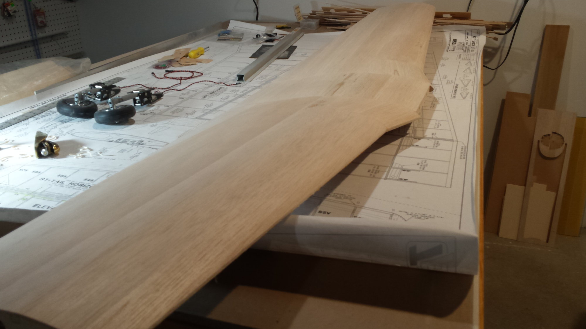
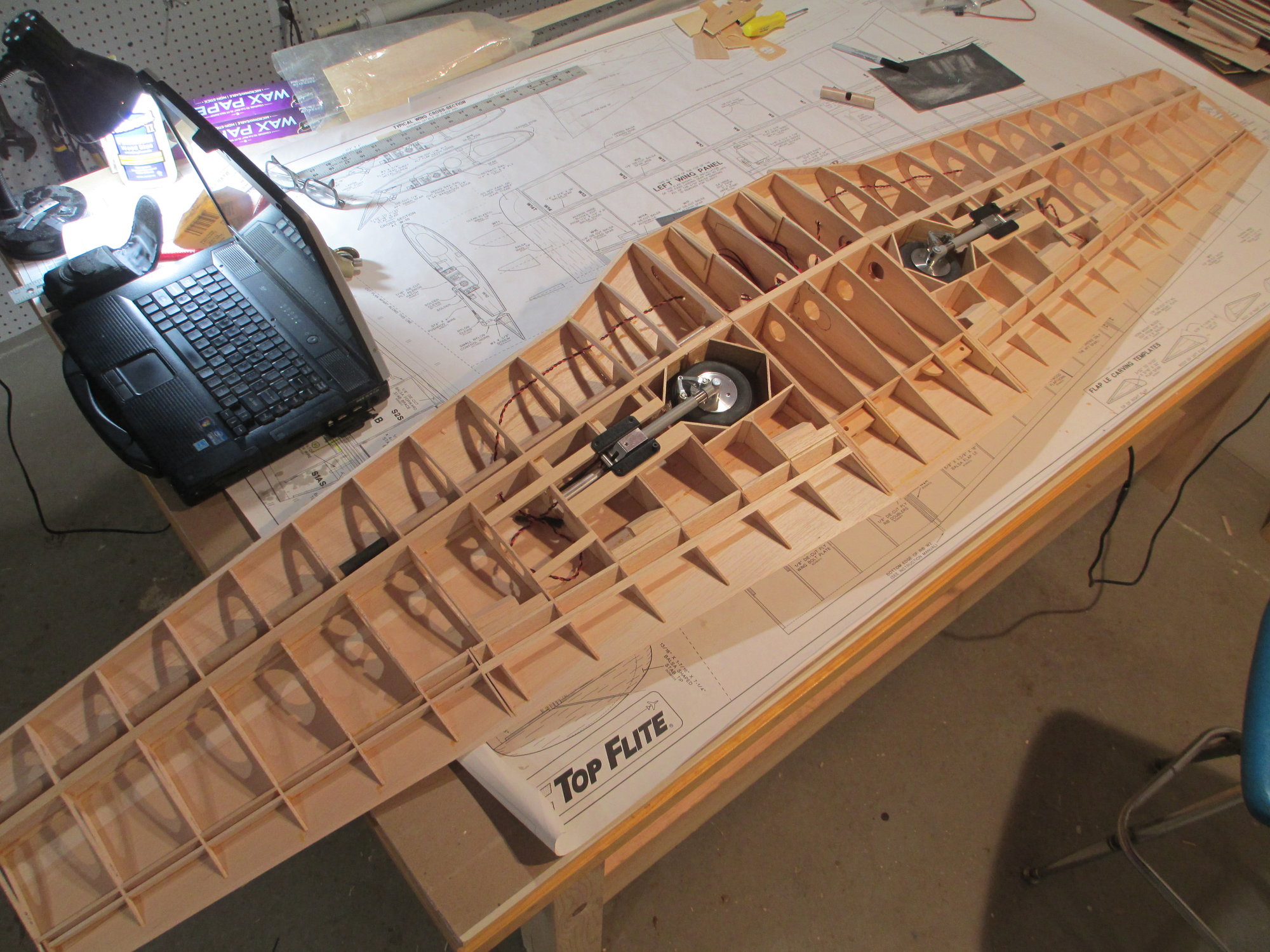
Wing is now one piece!
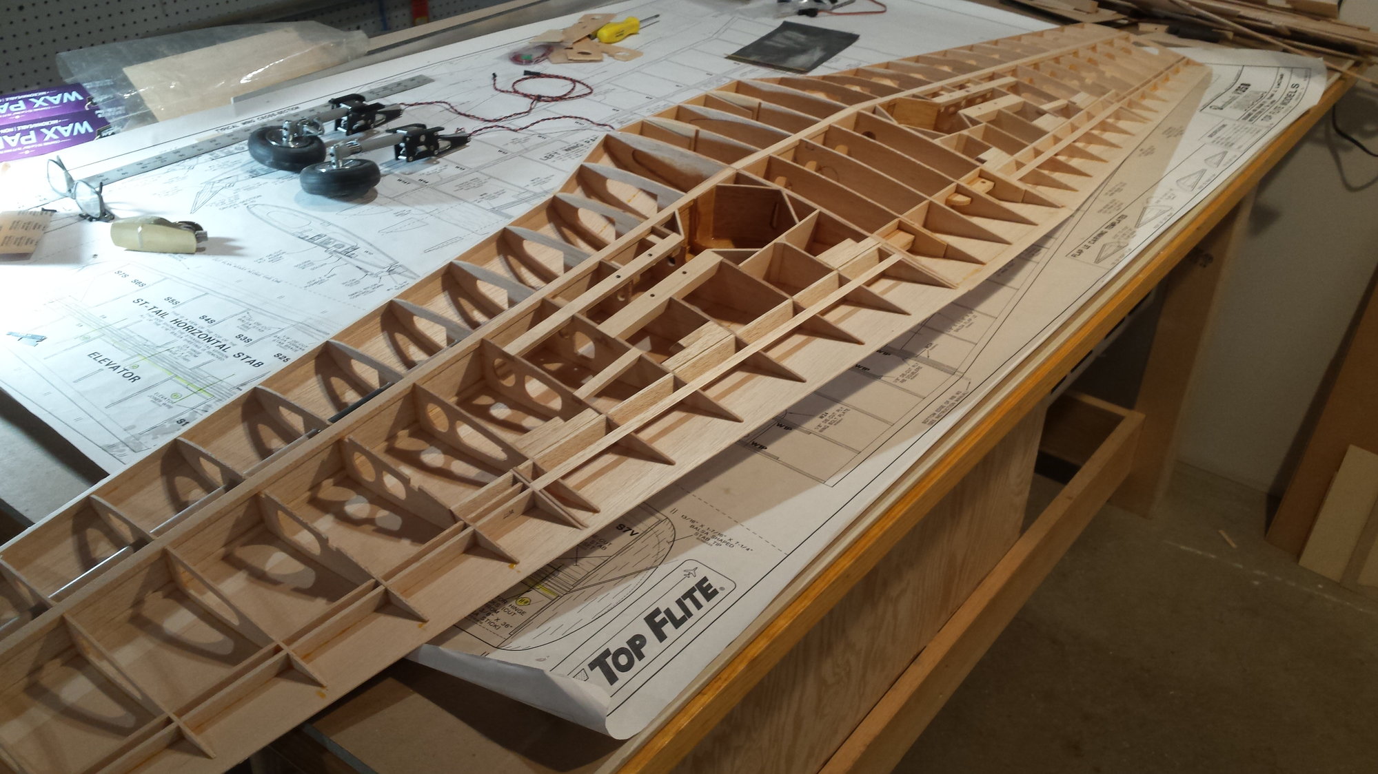
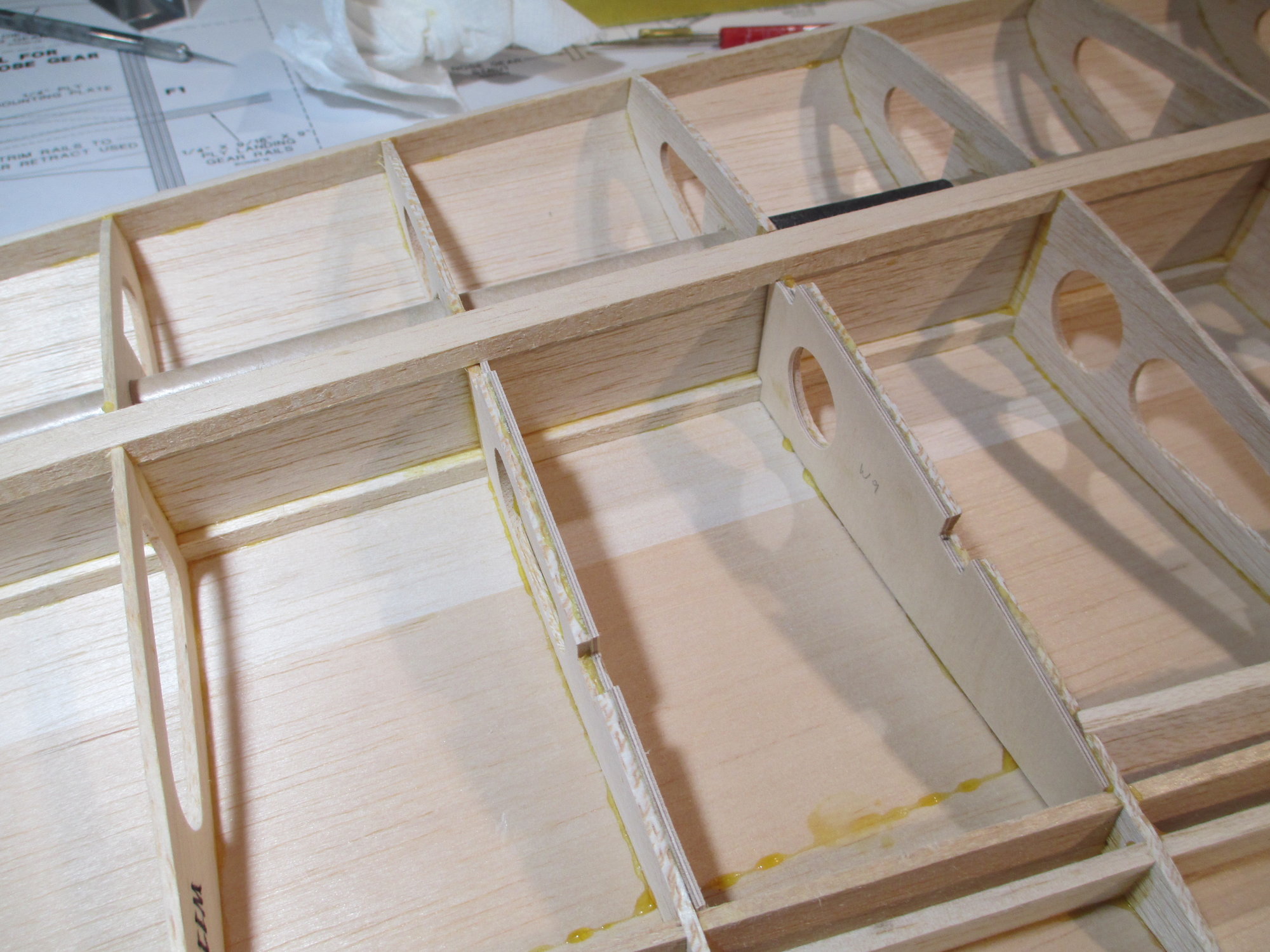
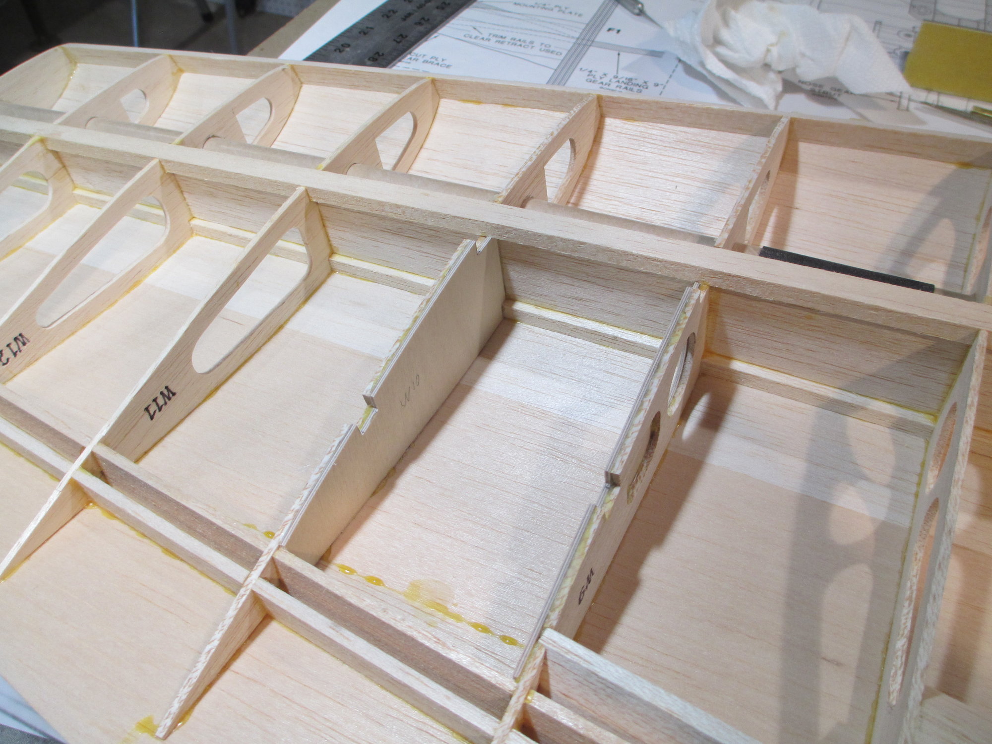
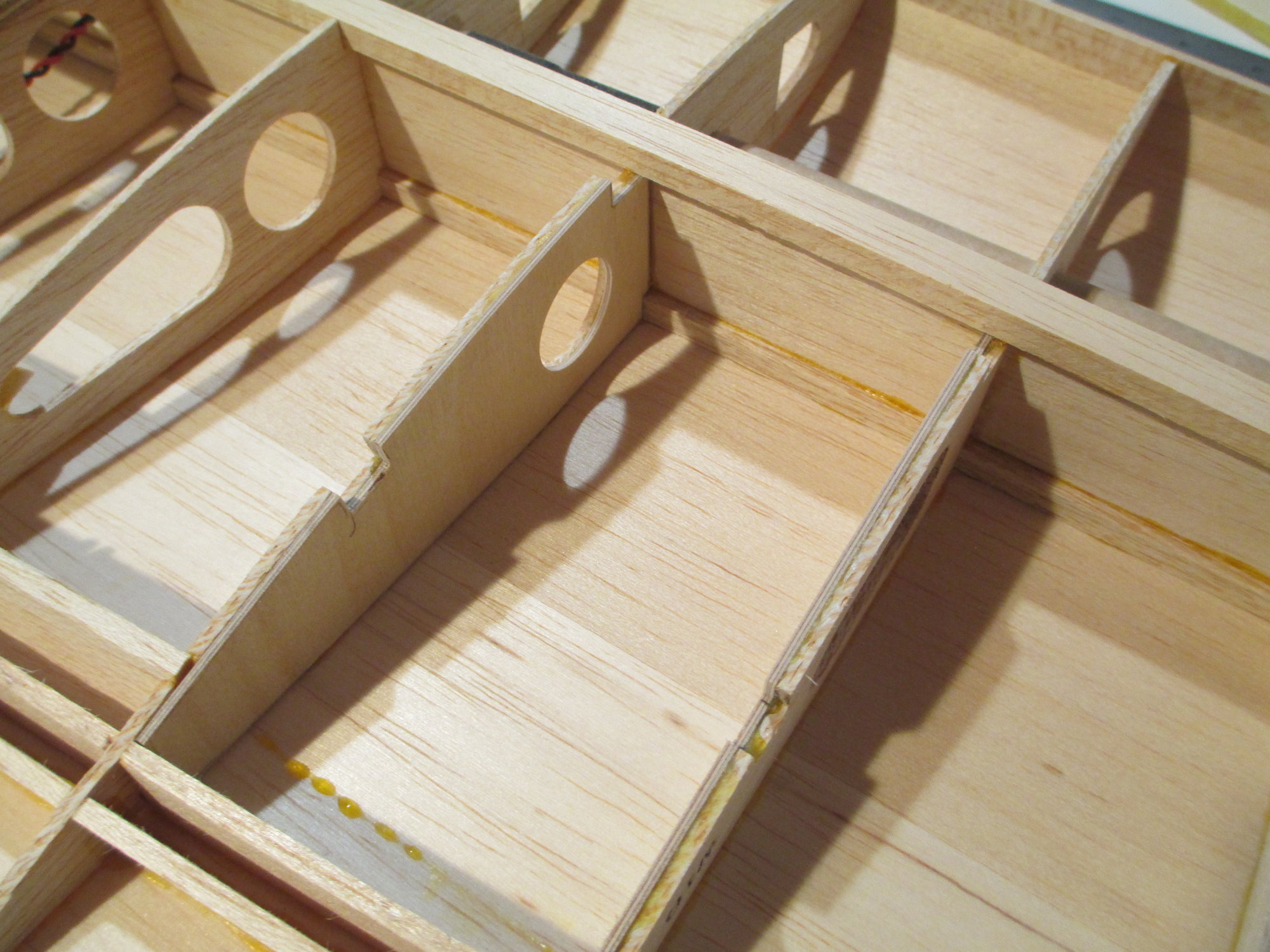
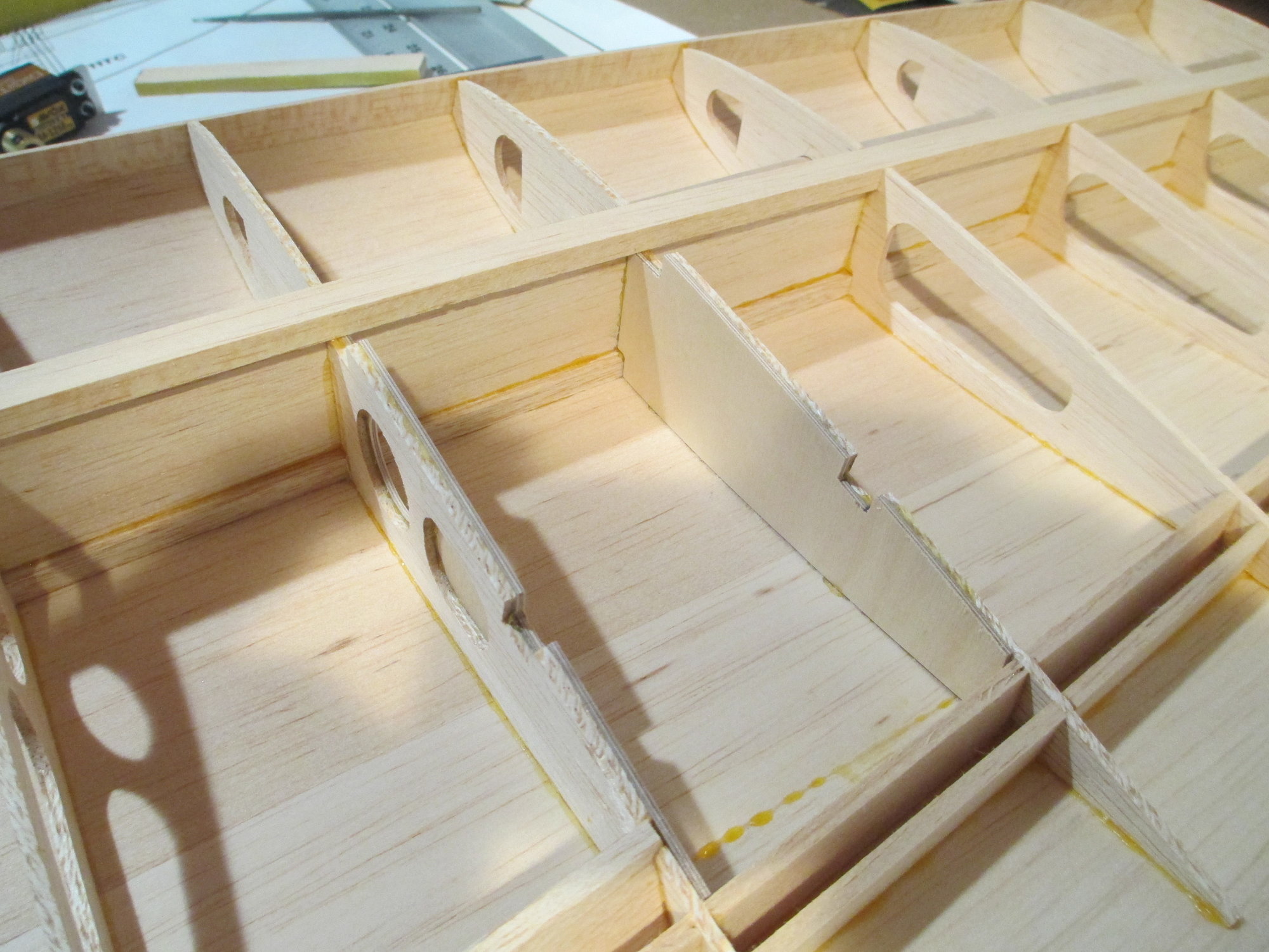
It was quite a bit of work to get the wing as you see here, from boxing in the wheel well to adding additional bracing.
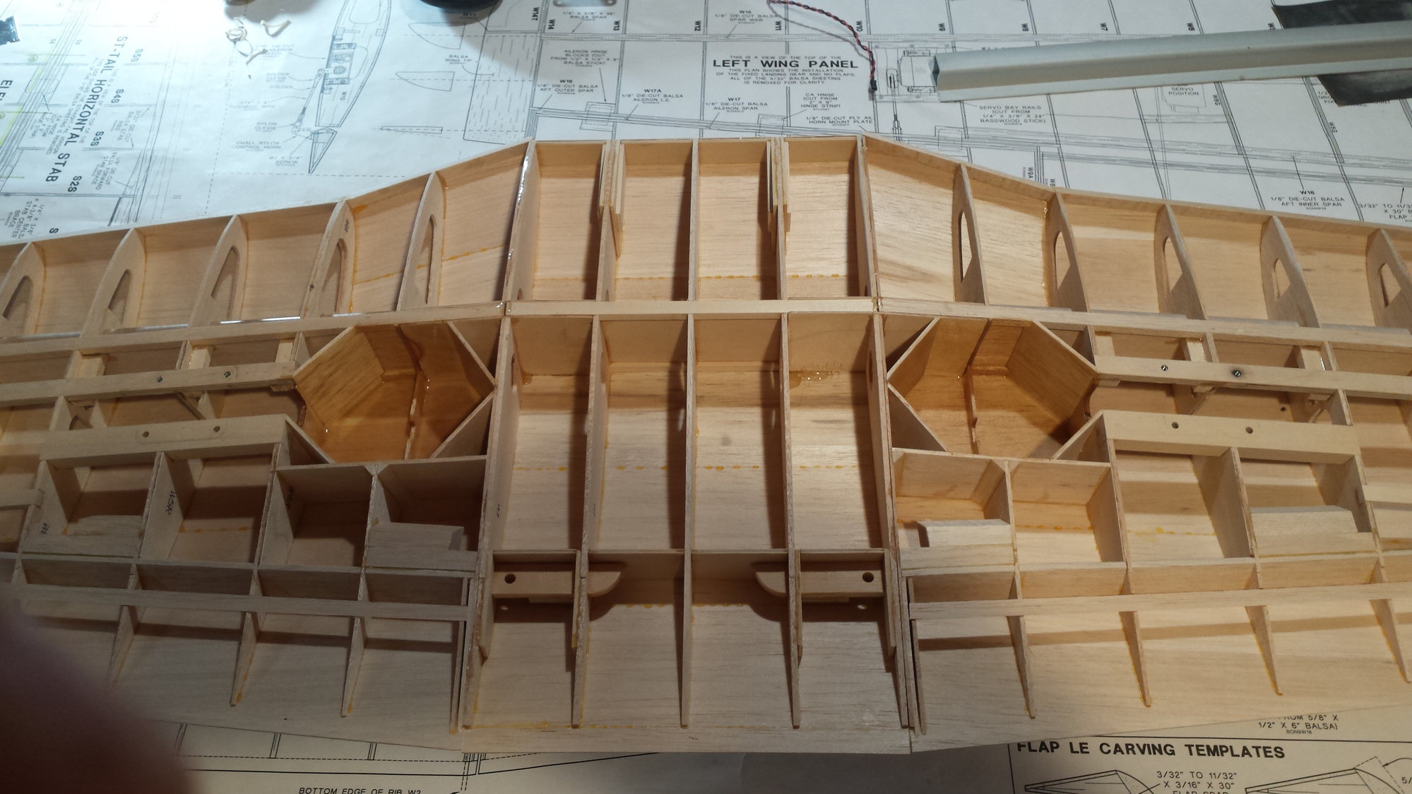
Close-up detail of the landing gear wheel wells. Before the sheeting can begin I have to sort out how the ailerons will operate...stay tuned, you're going to like this.


 08-31-2019, 02:16 AM
#229
Thread Starter
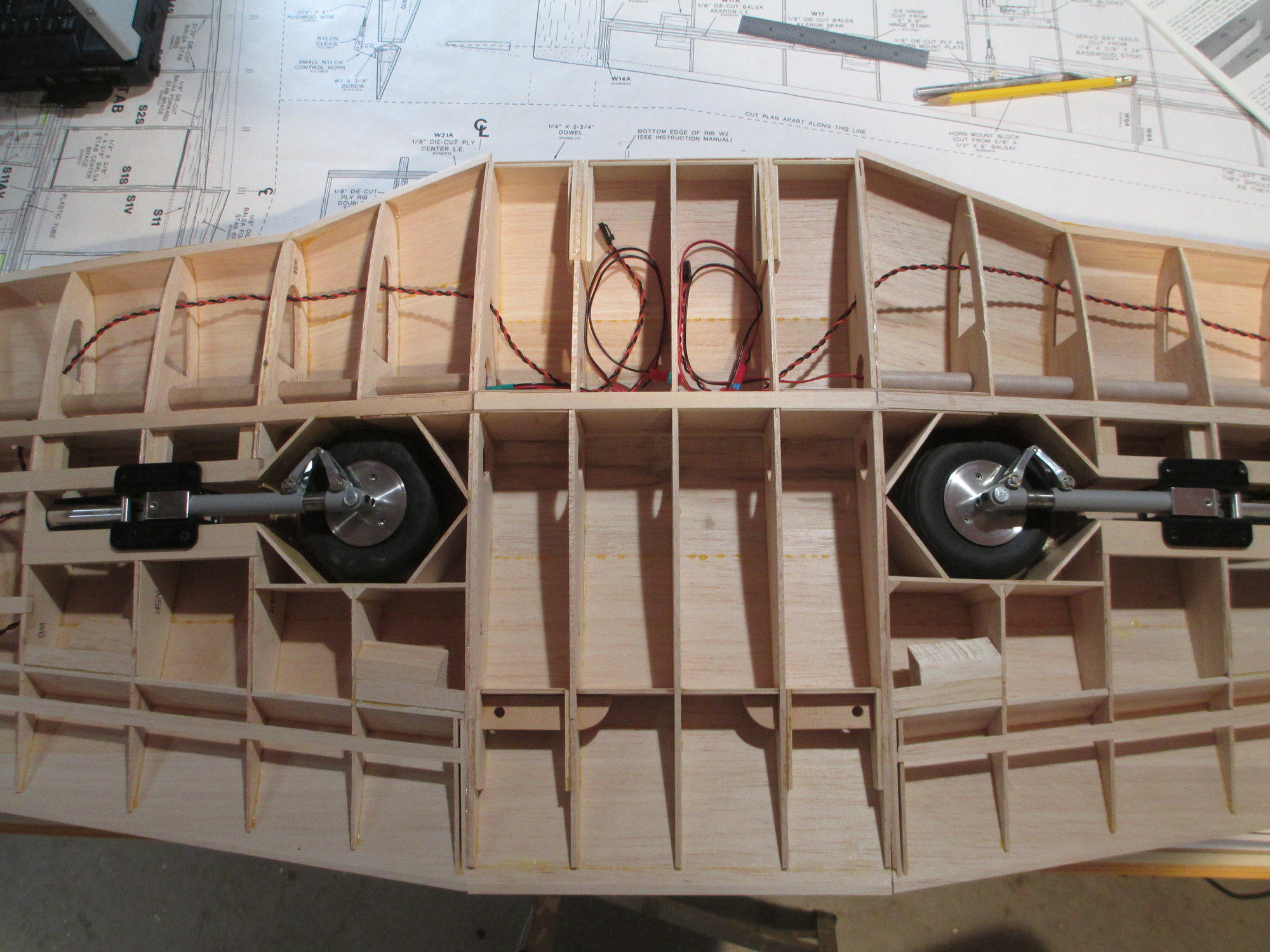
Retract extension wires (purchased separately from Robart) were run in place.
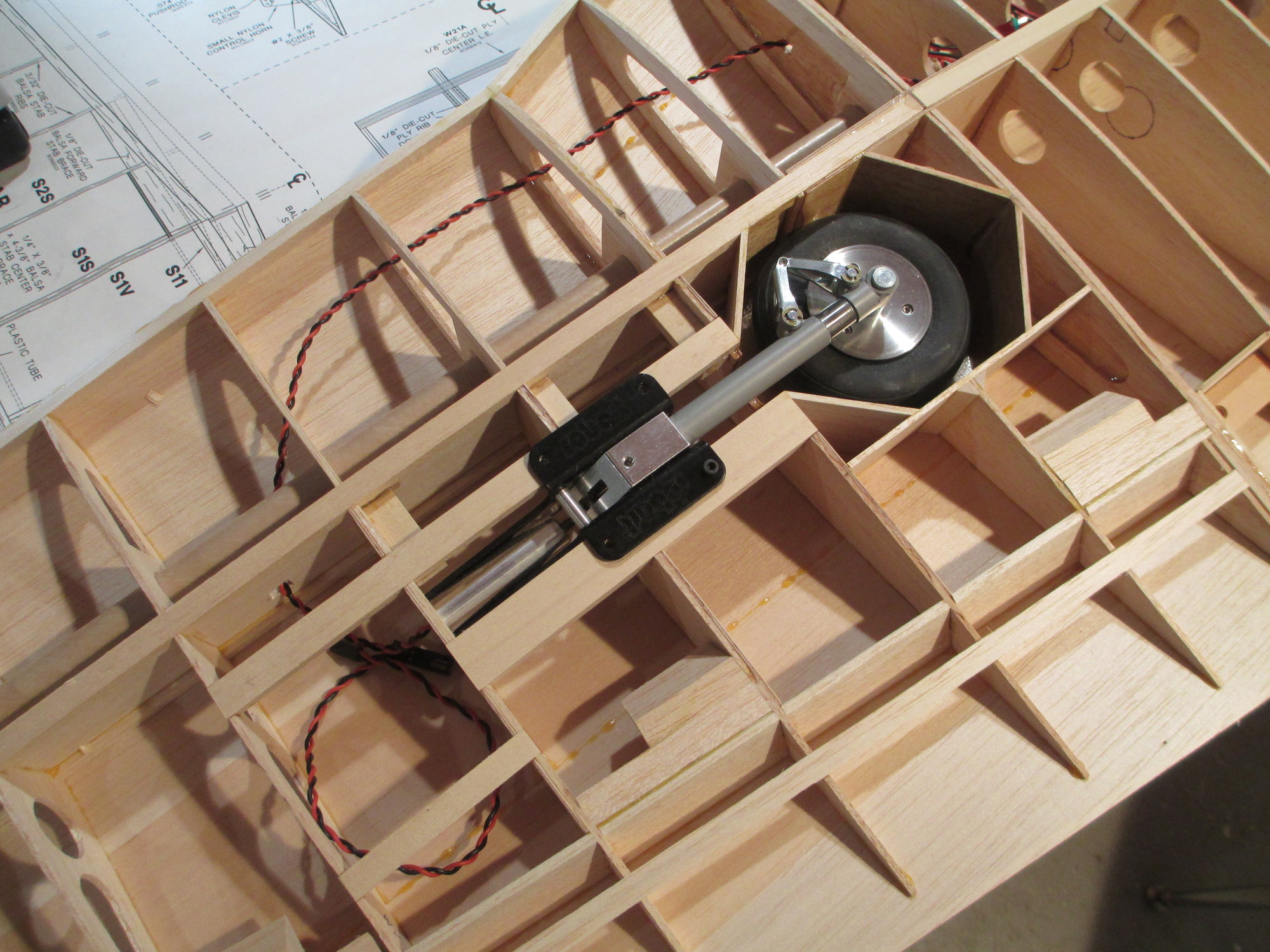
Note were I chose to to run the extension wire for the retract. I deviated from where the wires are shown on the plans. I much prefer to have the wire run in a part of the wing where there isn't a chance for for fraying or for the retract to tug on the wire during operation.
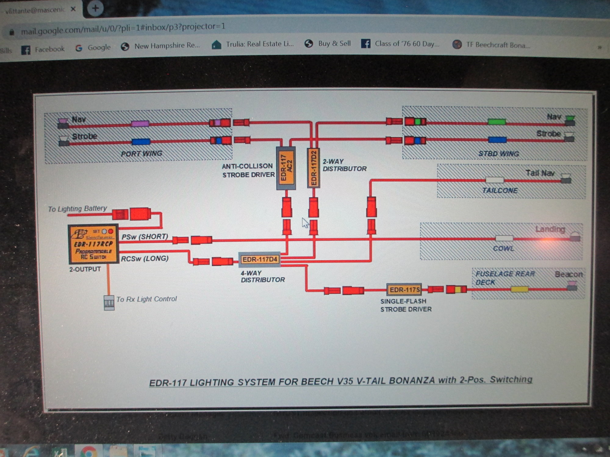
With the retract wiring completed it's time to run the navigational lights for each wing tip. Each tip will have two separate lights. One color (red, green), depending whether it's left or right along with a white strobe light. Here is the schematic that should clarify things. I think I may have already posted a picture of this schematic earlier...
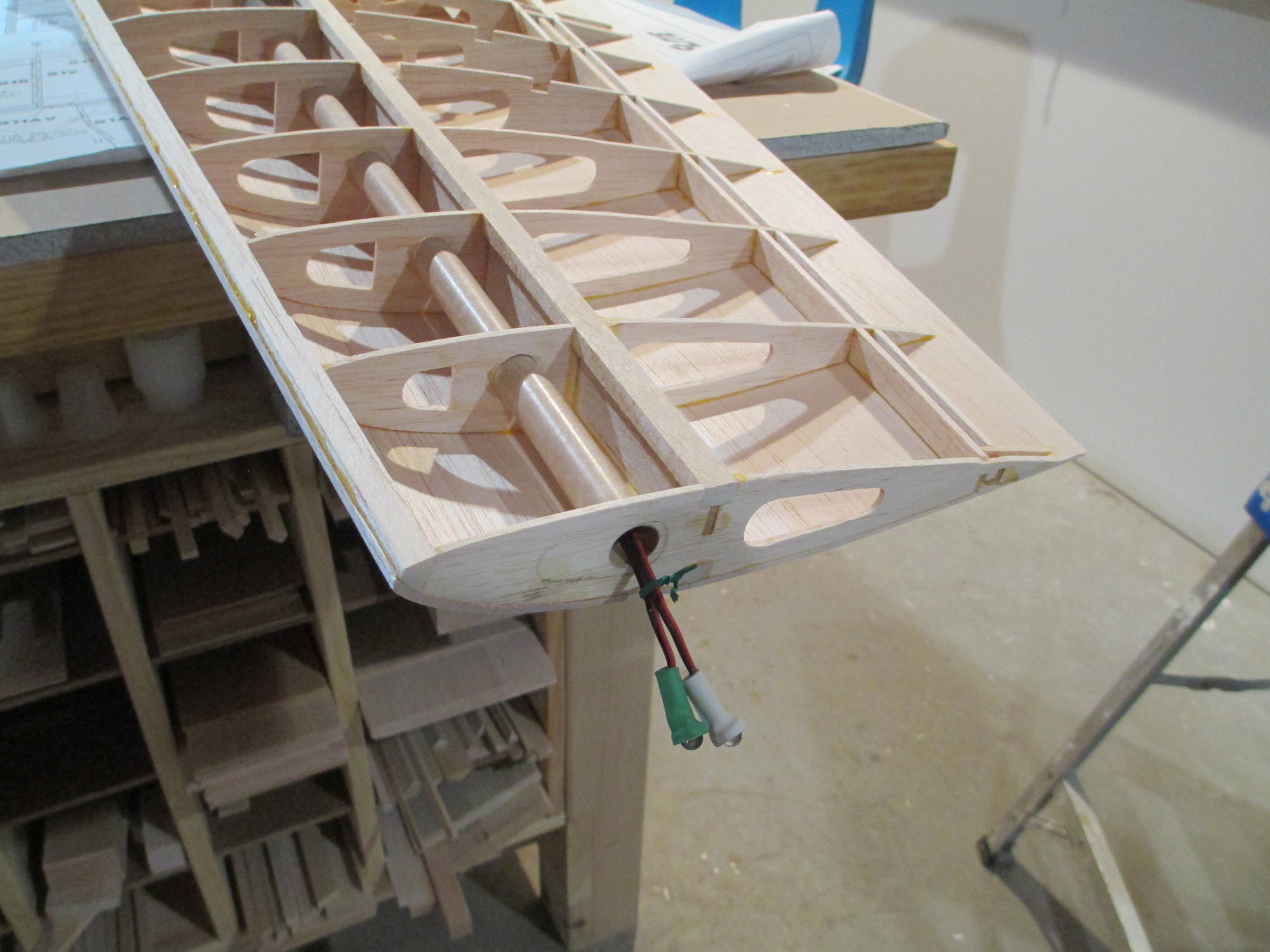
Here are the two wing tips lights for the right side. It was a snap to fish the wires through the existing rocket tube...
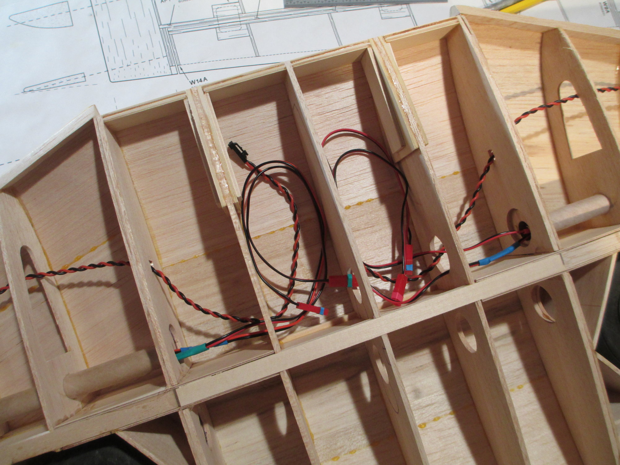
Close-up of were all the wires terminate. I will not drill any exit holes at this point. I will tend to that task after the wing is sheeted, glassed and painted. Doing it this way will ensure the wires wont get in the way or painted.
At this point the wiring for the wing is completed!
Last edited by VincentJ; 08-31-2019 at 02:31 AM.
08-31-2019, 09:10 AM
#230
Thread Starter
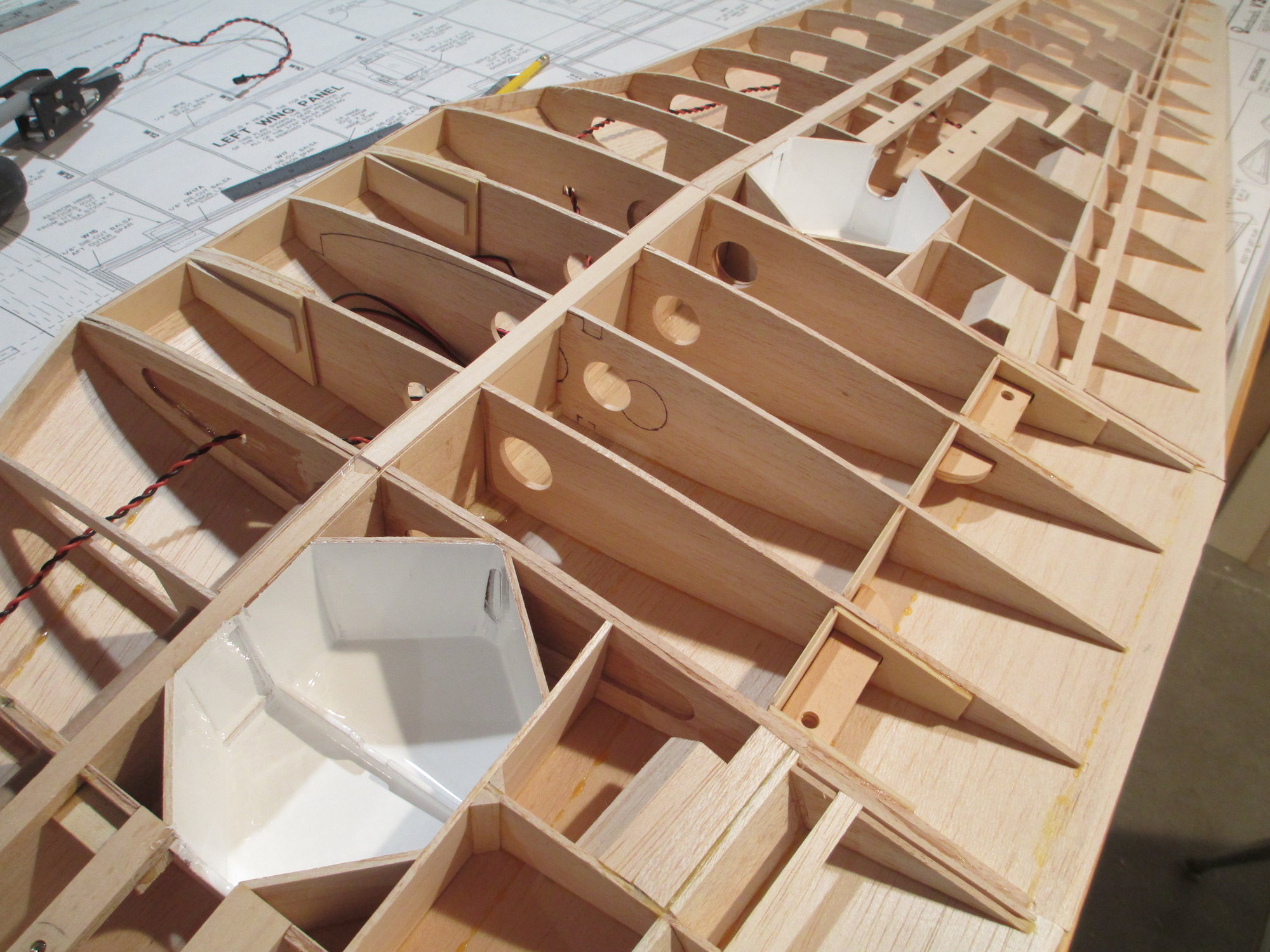
The wheel wells were painted white now as they are exposed, because after the sheeting is attached it would be very difficult to paint. I mixed a small batch of white Klass Kote Epoxy paint which I brushed on.
 08-31-2019, 11:01 PM
#232
Junior Member
Well I just spent way too much time going through this thread and looking at the pictures of amazing craftsmanship. Standards that I can hope to one day come close to matching.
09-01-2019, 01:37 AM
#233
Thread Starter
Thank you! It's so hard not to ding anything especially when you have a one piece monster of a wing. If you see areas of filler used on the surface it's usually because of a ding...
09-01-2019, 01:44 AM
#234
Thread Starter
Thanks for the compliment. While this particular model is reasonably complicated, the methods and building practices that I use can be duplicated by anyone on any model. I'm sure that with a little time and practice the results of your building will be every bit (if not better) as good as mine.
Last edited by VincentJ; 09-01-2019 at 11:33 PM.
09-01-2019, 11:29 AM
#235
My Feedback: (2)
Hi Vincent, I am wondering if you are a master carpenter by trade. My mentor who was a master carpenter by trade was also the most productive builder that I ever knew. He would build a airplane in one week no matter the size of the airplane. He had a friend who was very wealthy and he would show up once a month with a new kit for him to build and he built lot of airplanes over the years! Good work I like how you make it look so easy!
Thank You
Michael Johnston
Thank You
Michael Johnston
09-01-2019, 11:50 AM
#236
Thread Starter
Hi Vincent, I am wondering if you are a master carpenter by trade. My mentor who was a master carpenter by trade was also the most productive builder that I ever knew. He would build a airplane in one week no matter the size of the airplane. He had a friend who was very wealthy and he would show up once a month with a new kit for him to build and he built lot of airplanes over the years! Good work I like how you make it look so easy!
Thank You
Michael Johnston
Thank You
Michael Johnston
Last edited by VincentJ; 09-01-2019 at 11:34 PM.
09-02-2019, 06:39 AM
#238
Thread Starter
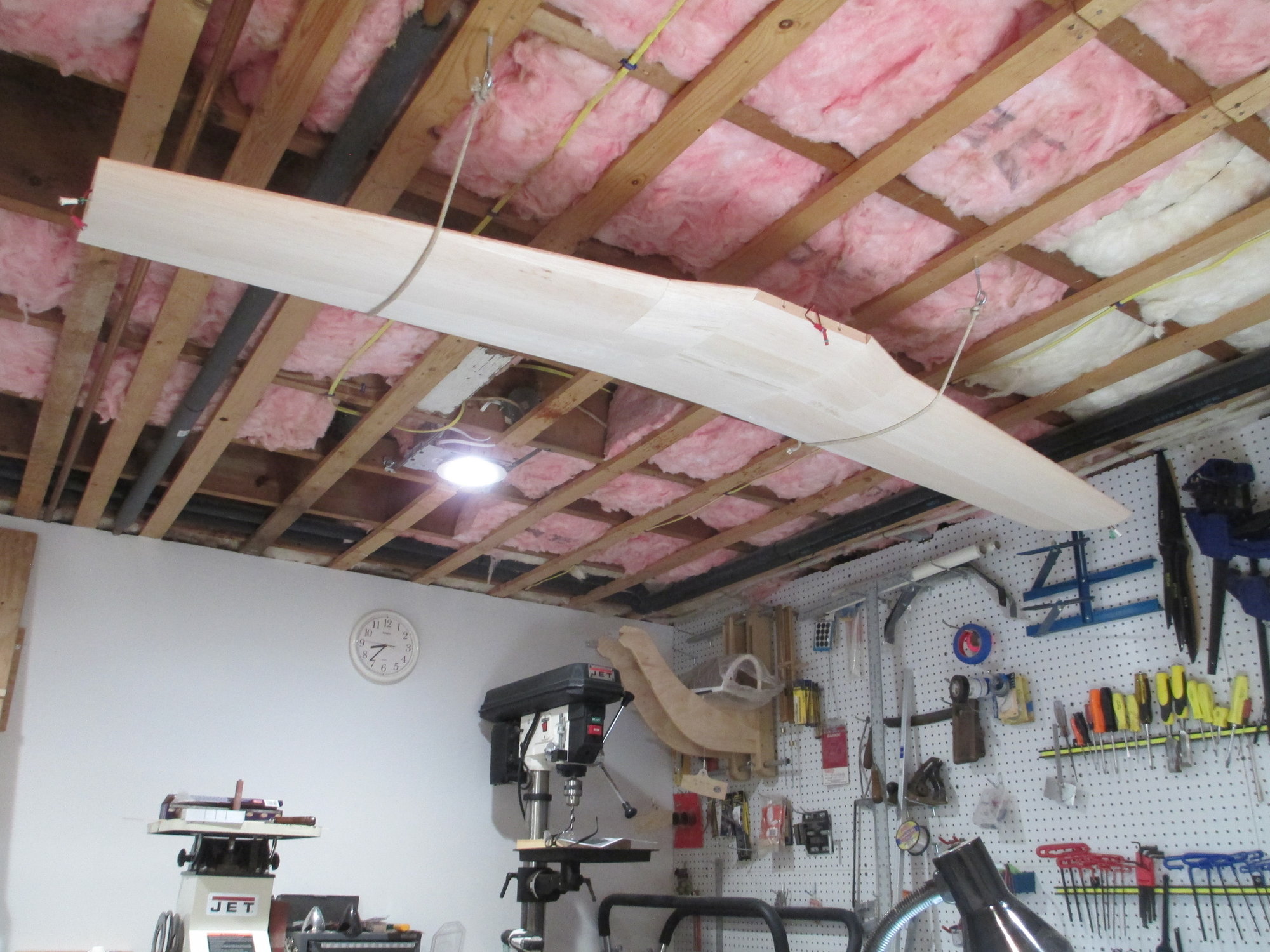
Waiting for some parts for the wing, so in the meantime this is where I store it in my small workshop to prevent it from getting dinged.
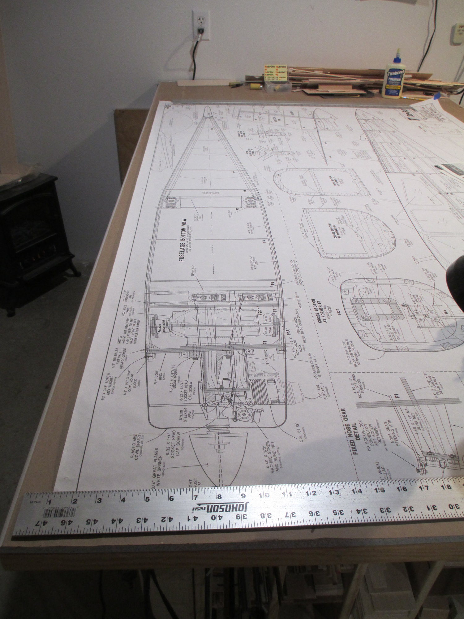
While waiting, I cleared off my worktable and decided to start to frame up the fuselage.
09-02-2019, 12:09 PM
#241
Thread Starter
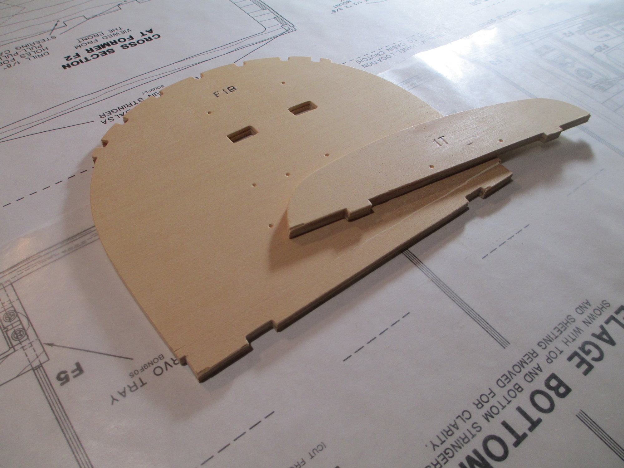
Construction of the fuselage first requires laminating two 1/8" plywood former's (F1) together with epoxy. This will ultimately become the firewall.
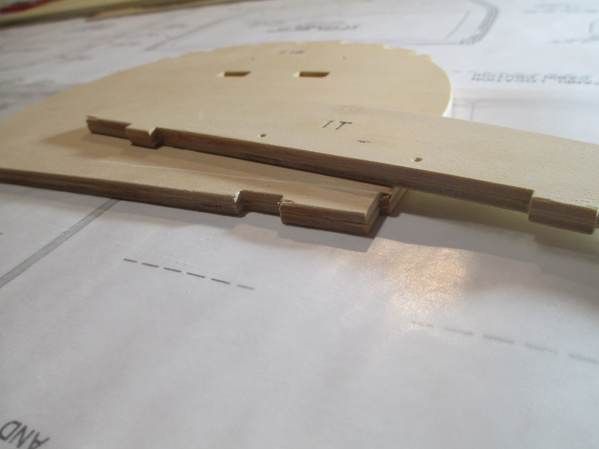
Close-up of the lamination's.
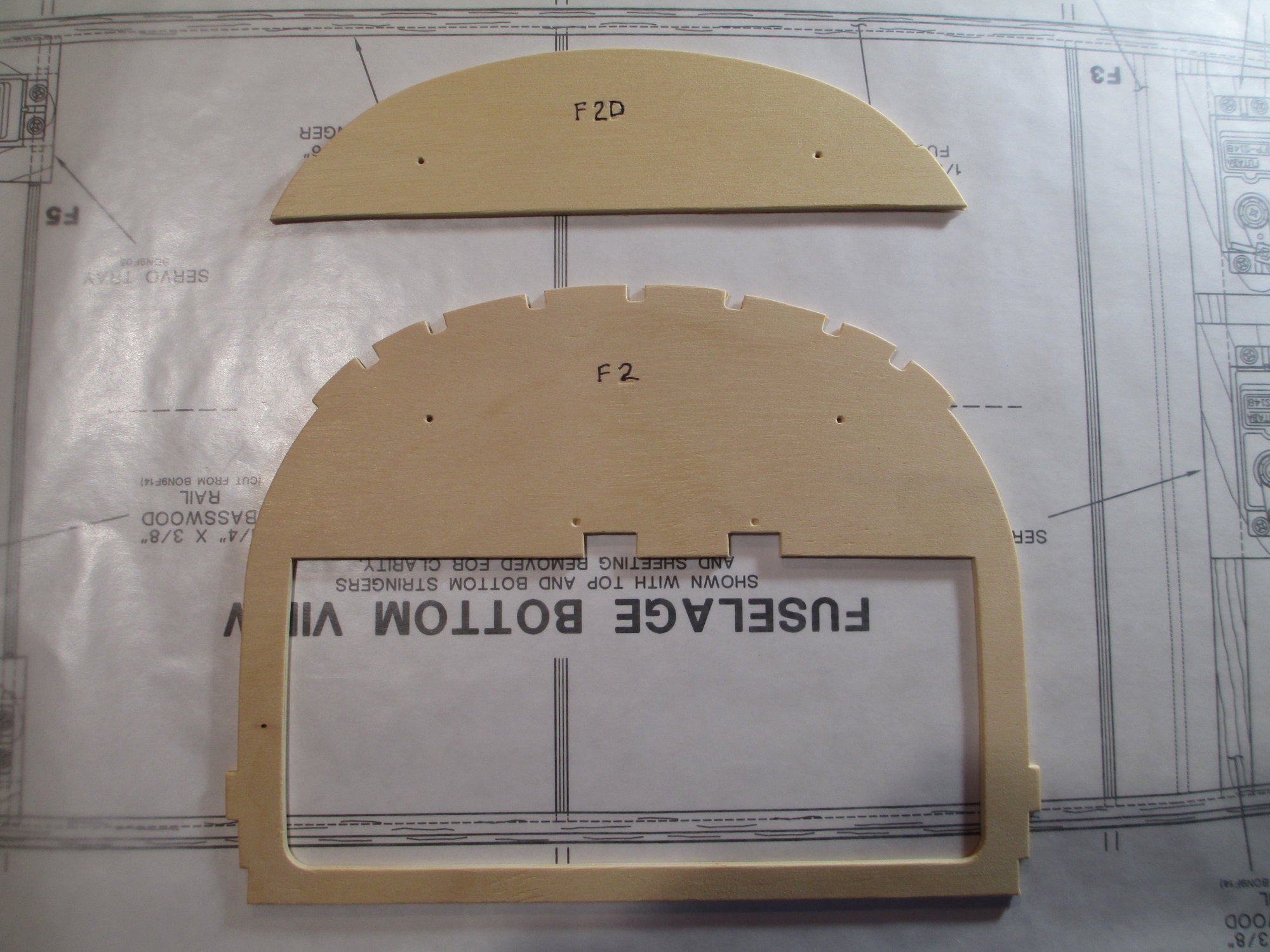
The second former F2, also requires F2D to also be laminated in front of F2.
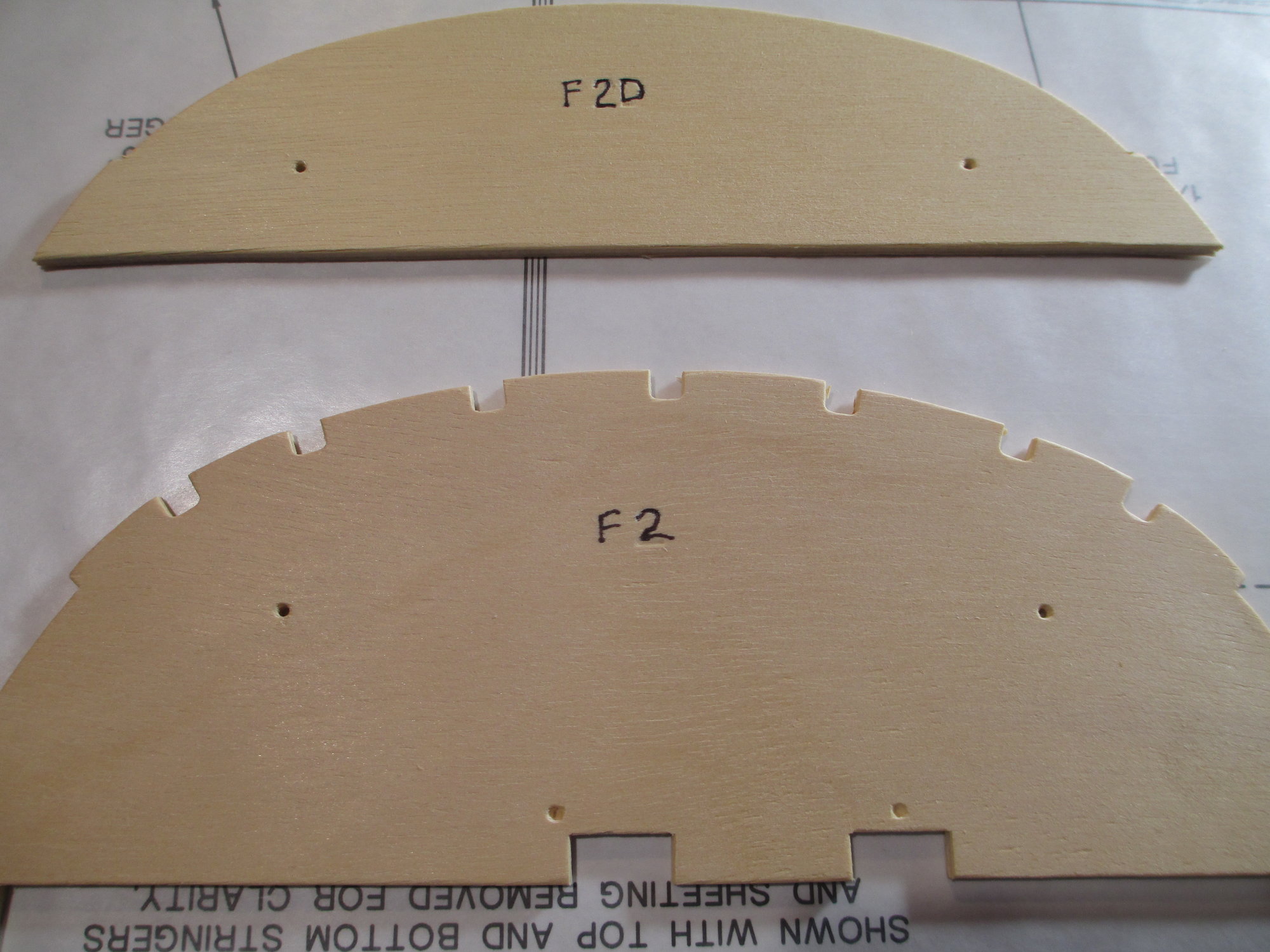
The plywood had indentations where I drilled two 1/16" holes that will be used to align both parts before glue-up.
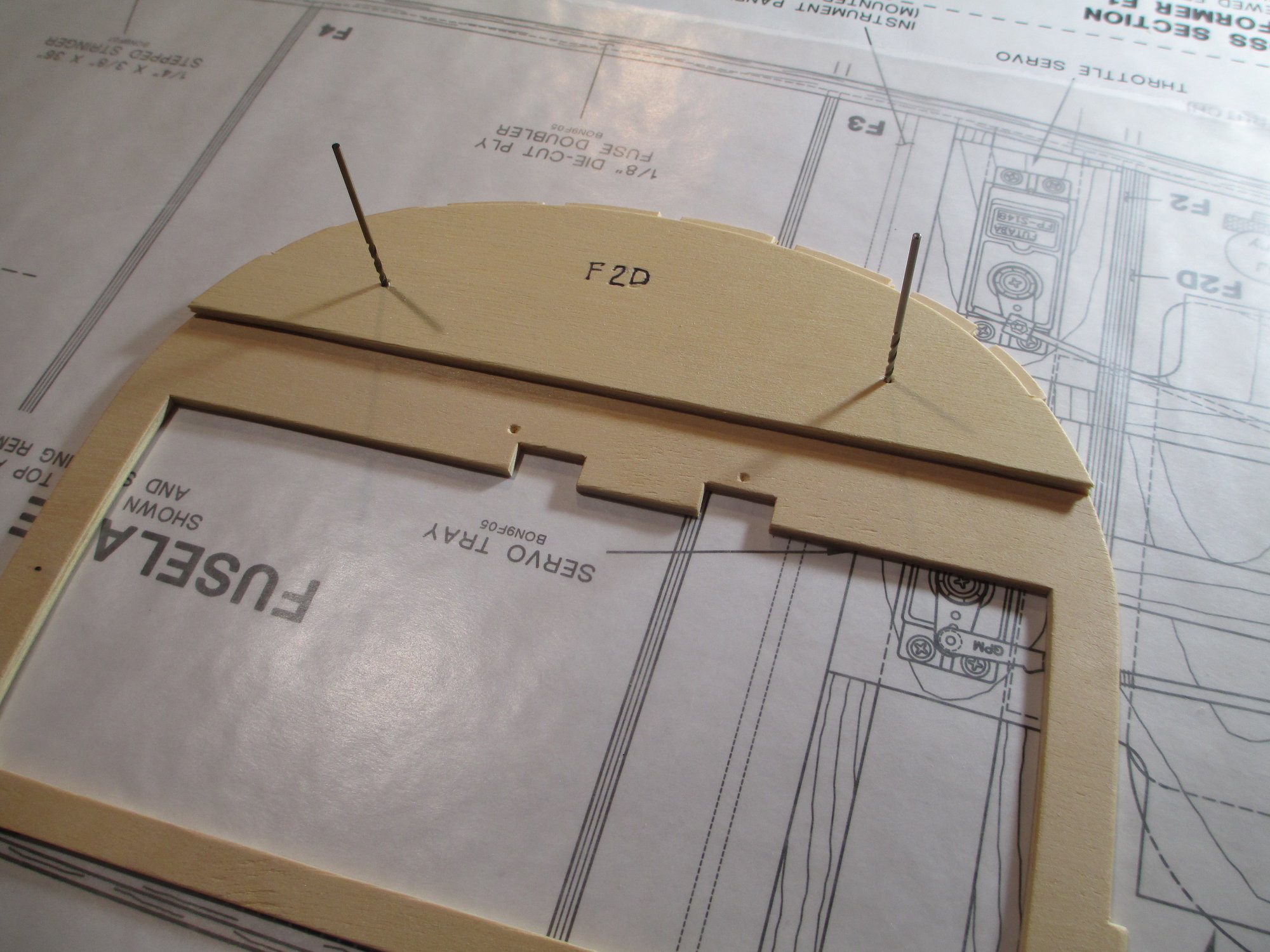
The 1/16" drill bits shown align F2 to F2D correctly. Once the epoxy cures, I will enlarge the holes to 5/16" using my drill press. These holes will allow the wing dowels to align to the fuselage.
Last edited by VincentJ; 09-02-2019 at 12:32 PM.
09-02-2019, 03:21 PM
#242
Thread Starter
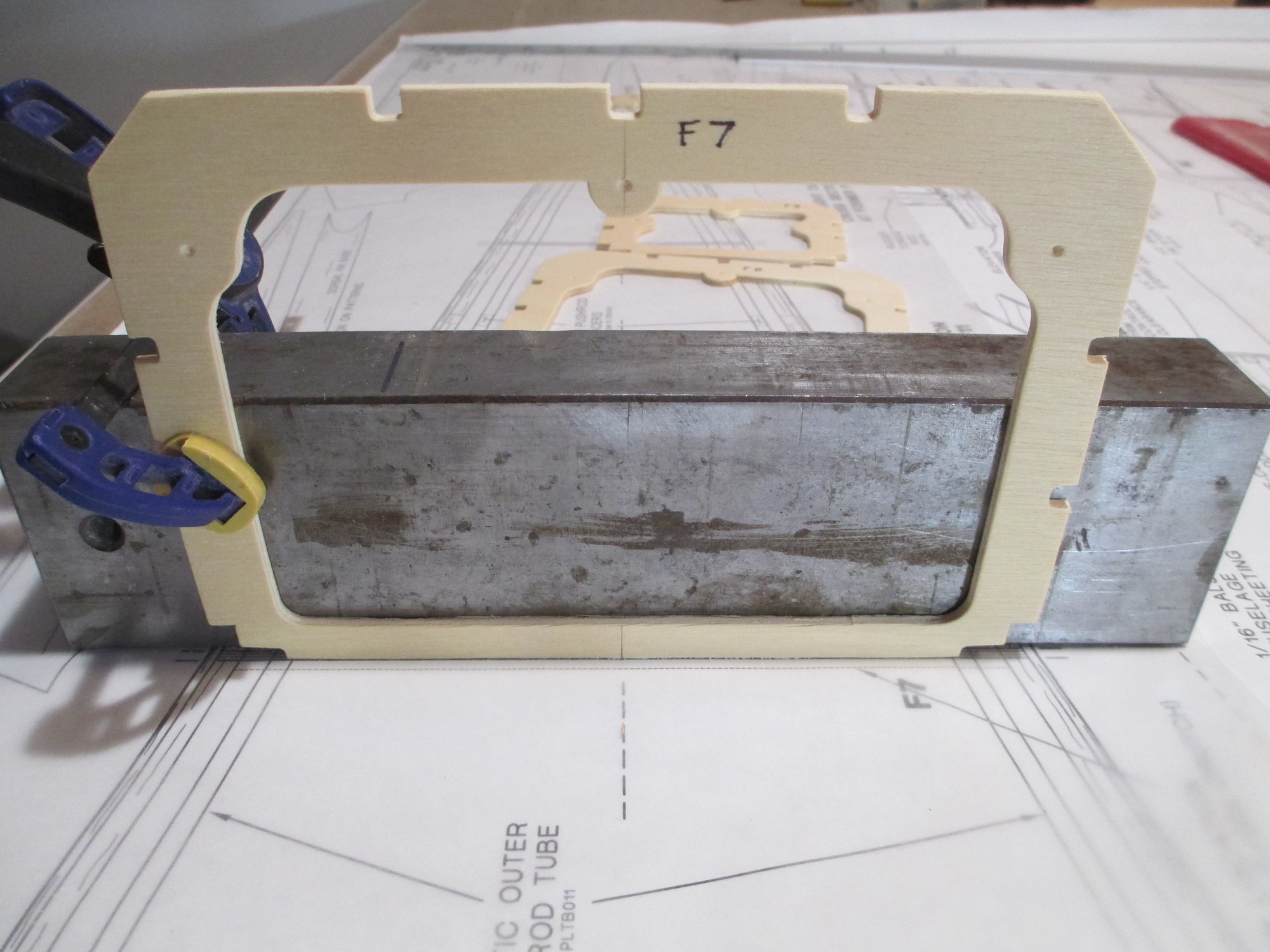
There's a lot of prep work that has to get done before any glue gets spread. All of the die cut plywood Formers were removed from their sheets. The front and rear side of each Former were sanded. Next, I sanded a true 90 degree angle to the bottom edge of each Former so they will sit flat on my build table during assembly. The next step is probably the most critical one. Marking the center line. I transferred the fuselage center line onto each Former.
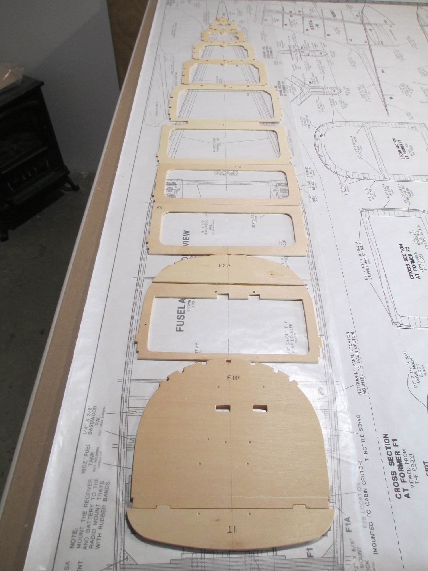
Each Former's center line was marked. I can't emphasize the importance of this step. When placing the Formers into position, I don't need to worry or look at the sides of each Former, as long as the center line is on point you wont build a banana boat!
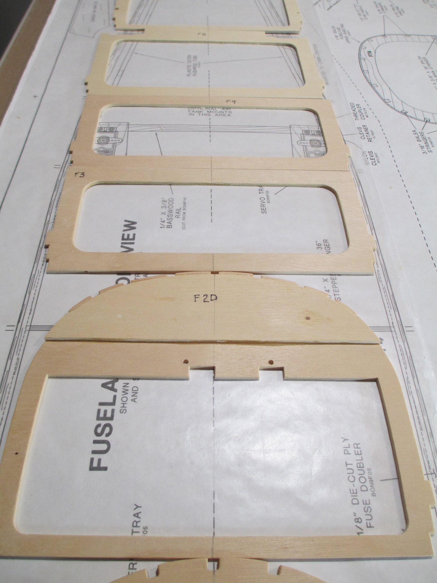
Close-up of center line. The center line is there on the plans, use it!!!
Last edited by VincentJ; 09-03-2019 at 02:44 AM.

 09-07-2019, 08:29 AM
#244
Thread Starter
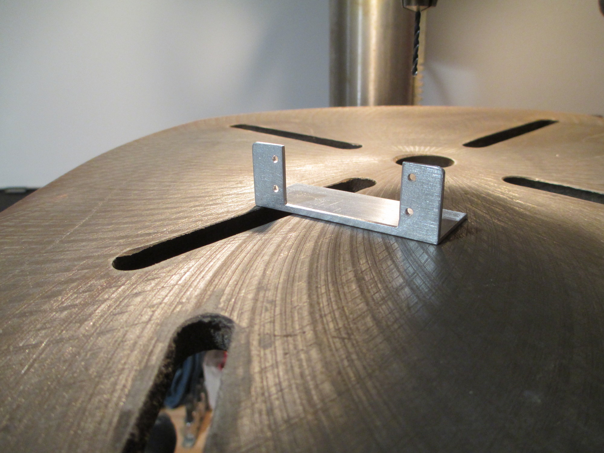
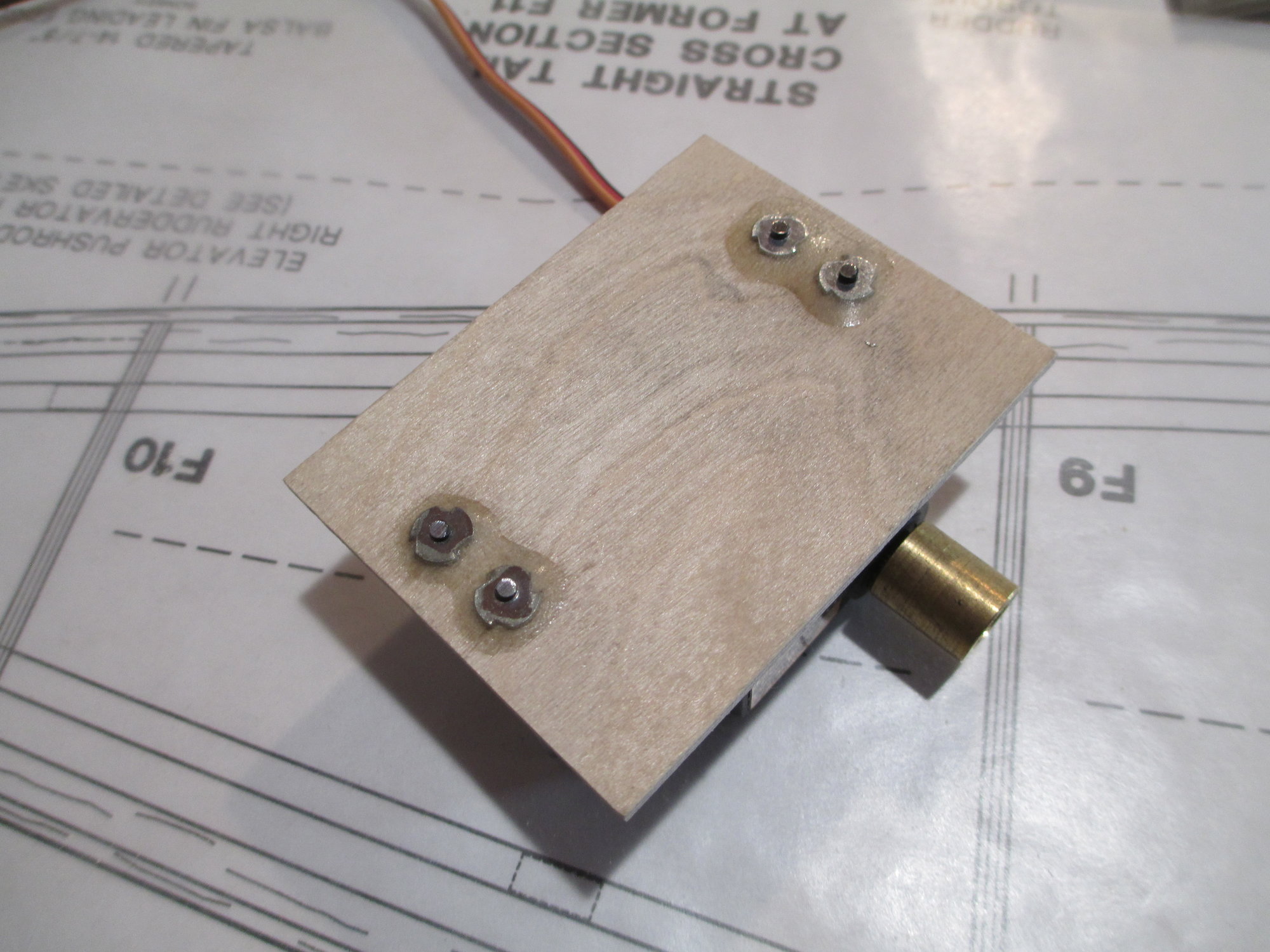
Stopped work on the fuselage for now because I have the parts that I was waiting for to complete the wing. I made this custom aluminum aileron bracket that will hold the aileron servo into position.
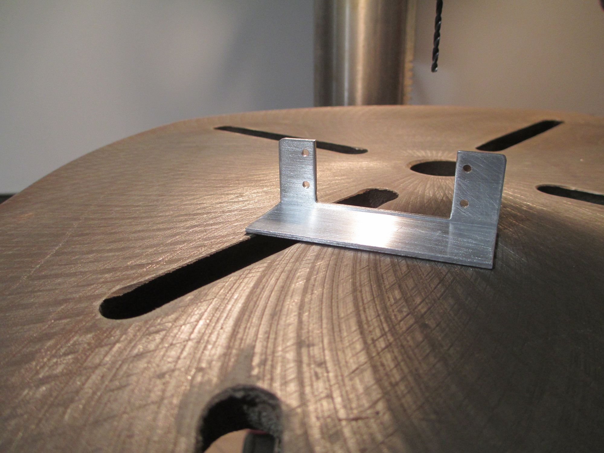
Back view of the bracket. These brackets are super strong, light and easy to make with just some simple hand tools. I will take them to my shop at school later and glass bead them to give them a nice uniform finish later.
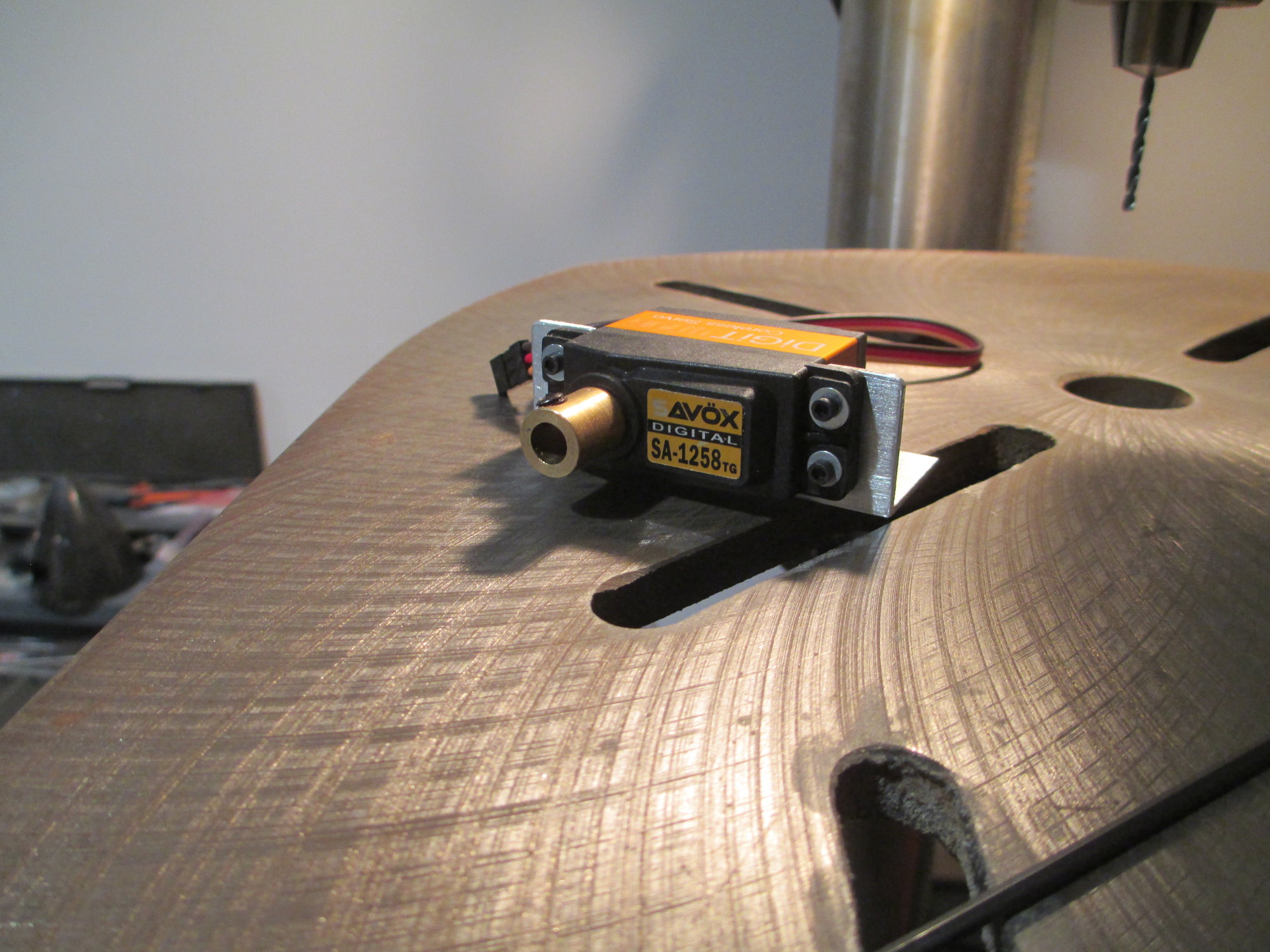
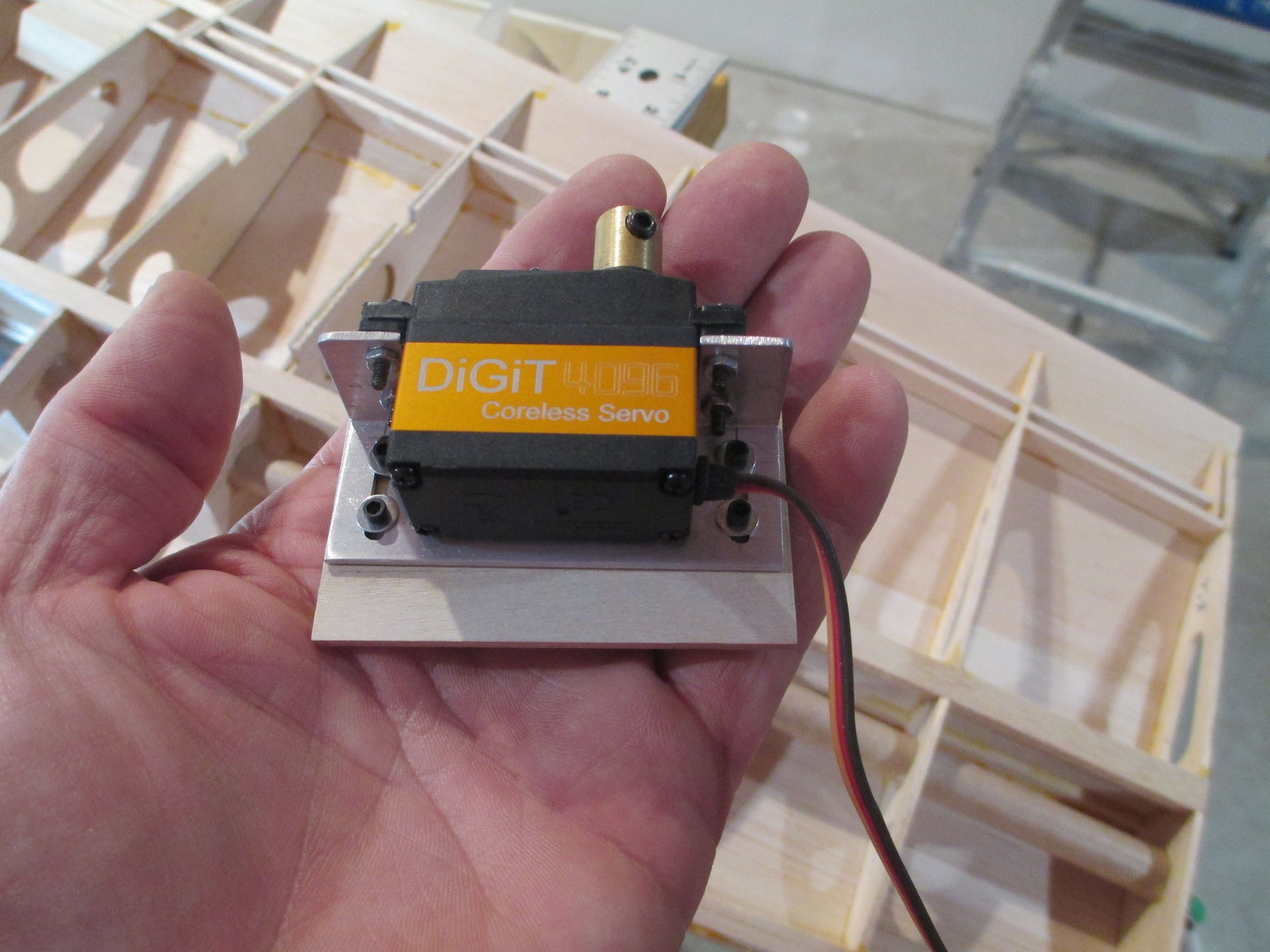
The servo is secured to the bracket using four 2-56 cap head screws and nuts. As I said, these brackets are super strong and I've never had a failure using them in any of my other planes.
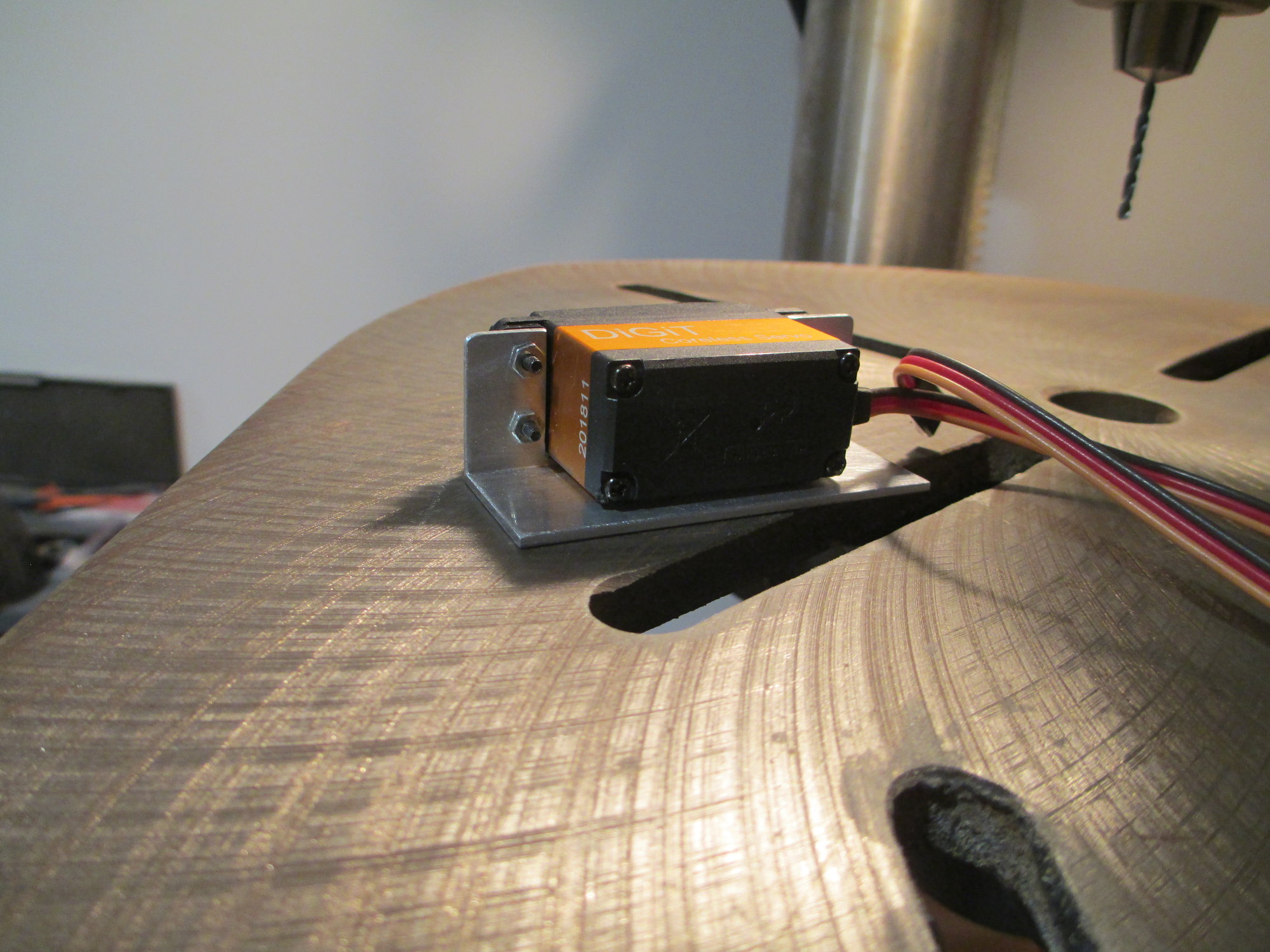
Back view. When making these brackets, be sure to leave 1/16" clearance or more between the servo and the bracket to avoid the air-frame's vibration from getting to the servo.
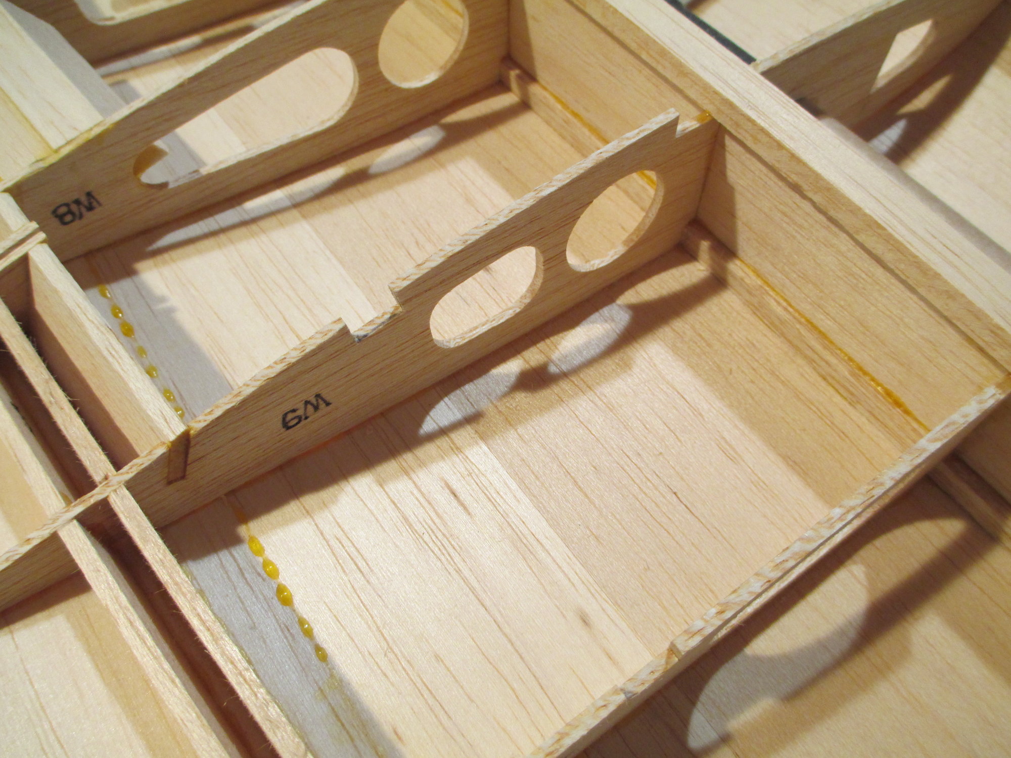
The bay between ribs W-9 and W-10 will support the aileron servo. I want to strengthen these two ribs by laminating 1/16" plywood to their sides.
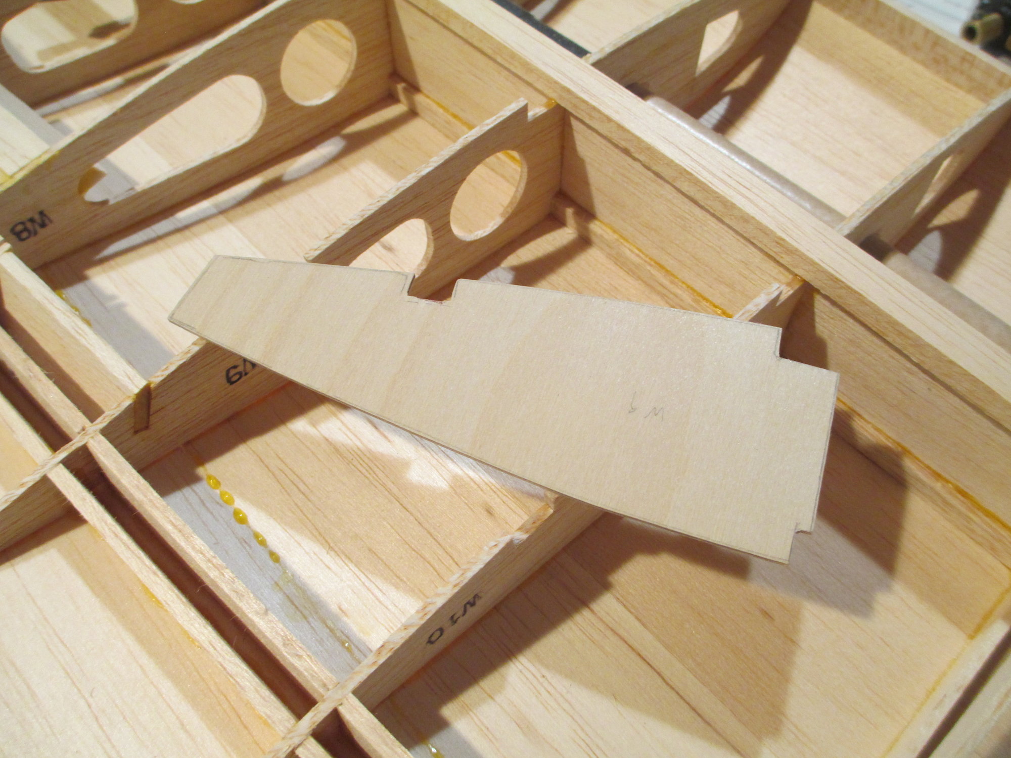
Here is the blank that just needs a bit more work before I glue it into position.
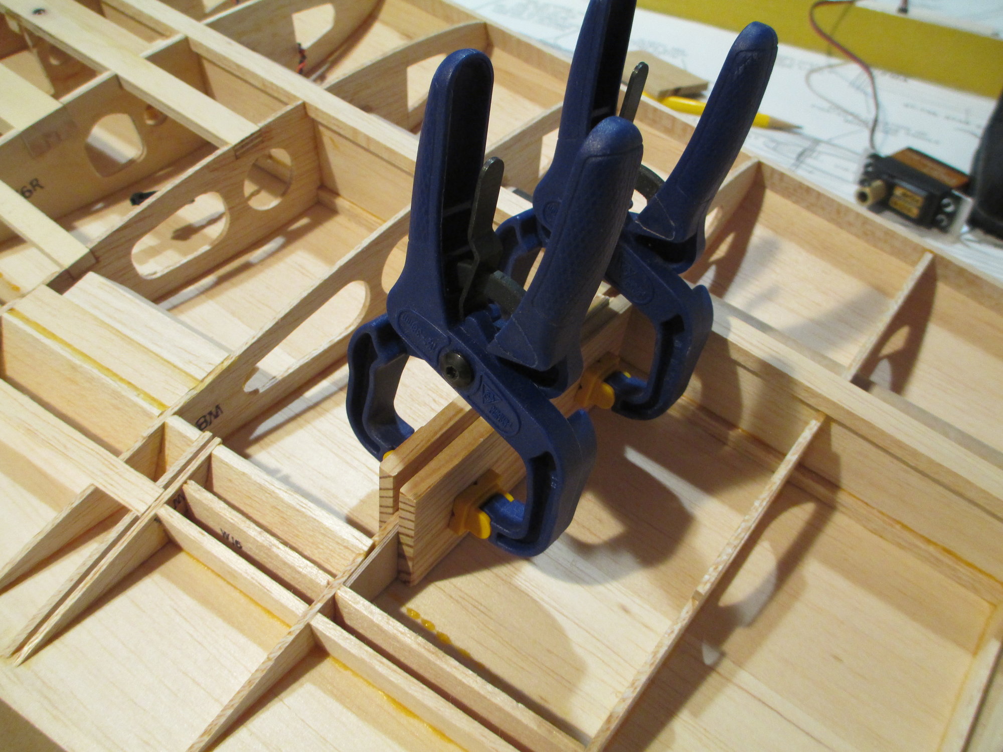
Blank is now glued and clamped into position.
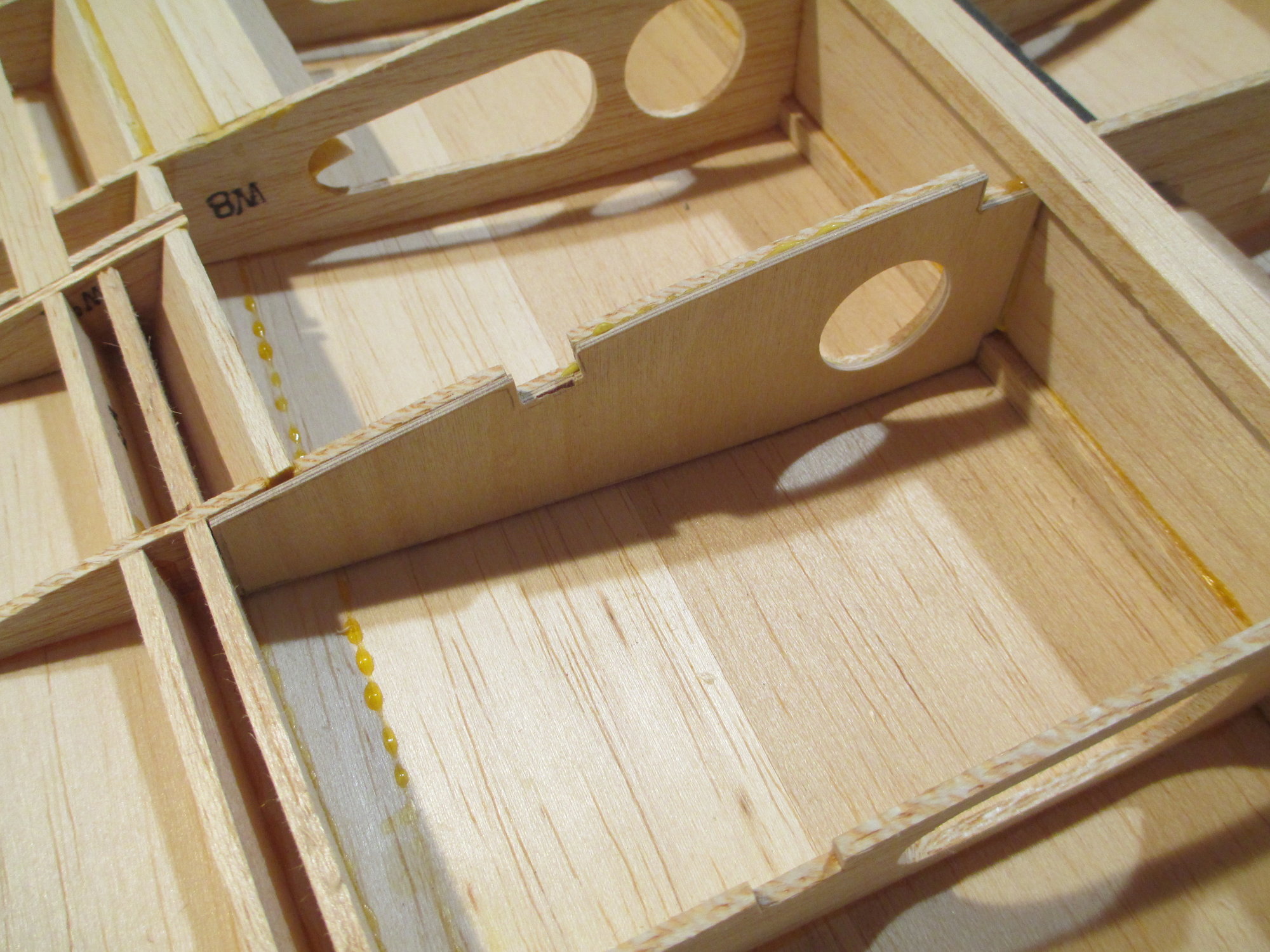
End result is a much sturdier rib that will not flex.
09-07-2019, 12:19 PM
#245
Thread Starter
All of the ribs that support the aileron servos have been laminated with plywood are completed.
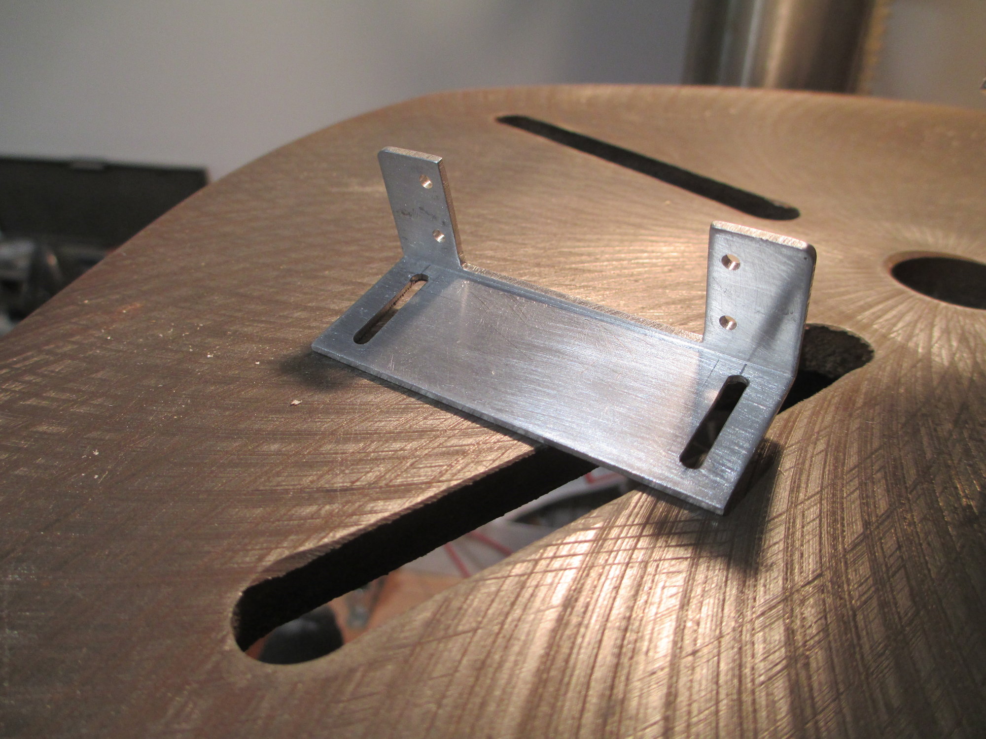
I added two slots at the base of the aileron servo brackets, this will allow the bracket to be adjustable. At this point it may not make any sense, but in sort order all will be revealed...
09-07-2019, 04:20 PM
#246
Thread Starter
I'm incorporating something that I've never done before in any build. The ailerons are going to operate without any visible linkage. This will be accomplished using a Rotary Drive System (RDS) that has been used by the slope gliding community for some time now. It hasn't been popular in RC scale building, and I'm not really sure why that is. I did a lot of research on the best way to accomplish this task and settled on this method. It was important to my partner Bob and I, as our goal to enter this plane in various scale competitions deduct points for any visible linkages. Not happy with what was on the market for purchase, we decided to make most of the components to fit our needs. Luckily Bob's nephew Scot, is a machinist and made the drive shafts for us! I will be sure to explain the steps involved as well as document each step with pictures to make the process more clear and hopefully brig some attention to this method of actuation...
The servo bracket is bolted to the plywood mount which will get epoxied between the rib bays that I reinforced.
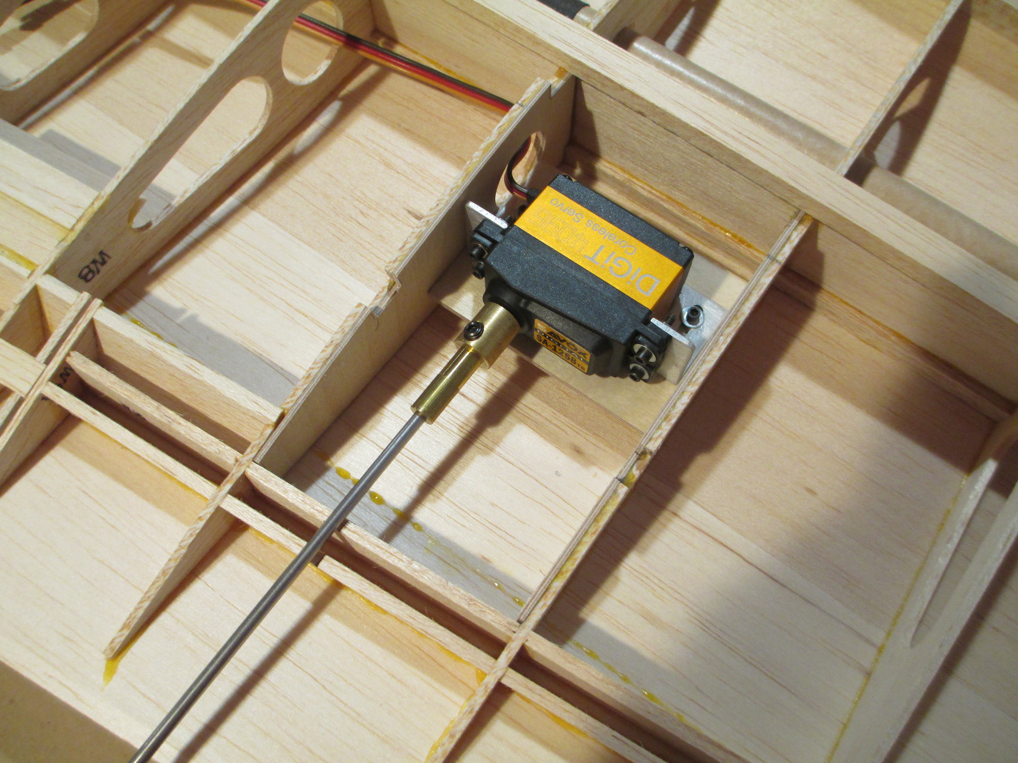
The drive shaft is connected to the splined servo output shaft through a coupler. At this point I'm only trying to determine where the drive shaft will exit the wing's trailing edge.
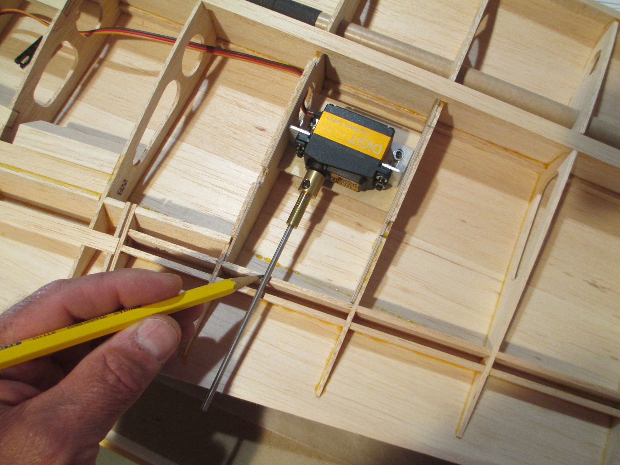
Using a pencil, I'm marking the exit position of the drive shaft.
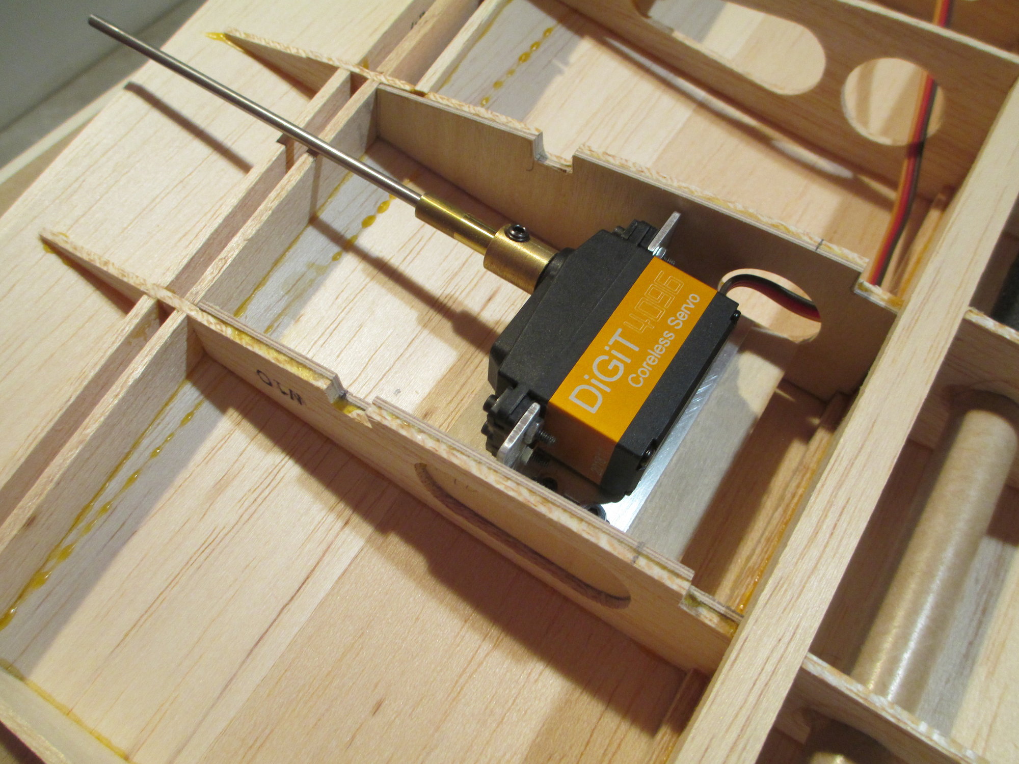
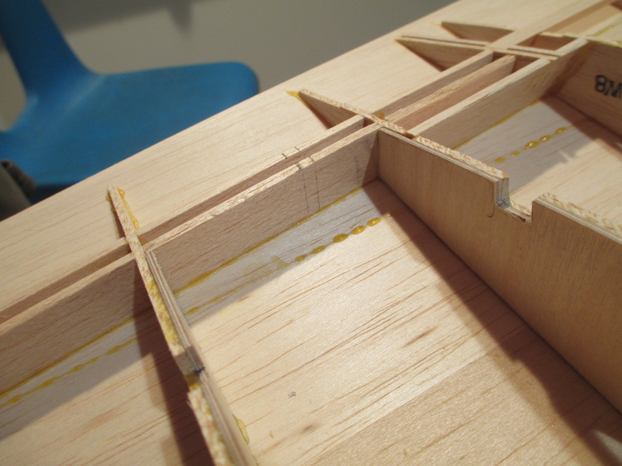
The pencil lines indicate the exit position.
The servo bracket is bolted to the plywood mount which will get epoxied between the rib bays that I reinforced.
The drive shaft is connected to the splined servo output shaft through a coupler. At this point I'm only trying to determine where the drive shaft will exit the wing's trailing edge.
Using a pencil, I'm marking the exit position of the drive shaft.
The pencil lines indicate the exit position.
Last edited by VincentJ; 09-07-2019 at 11:53 PM.
09-08-2019, 02:52 PM
#248
Thread Starter
I am using a RDS drive on my 1/4 scale Piper Cherokee. rudder and ailerons, works very good. Make sure your pockets are close fitting the driveshaft wire. You can see it here.
Last edited by VincentJ; 09-09-2019 at 05:57 AM.
09-09-2019, 03:31 PM
#249
Thread Starter
The adjustable aluminum servo bracket is held to the plywood mount with four 2-56 blind nuts.
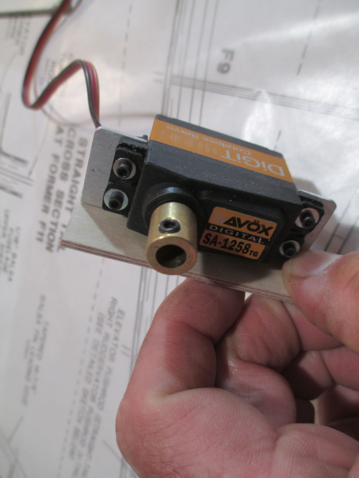
The coupler is secured to the servo with your typical servo screw.
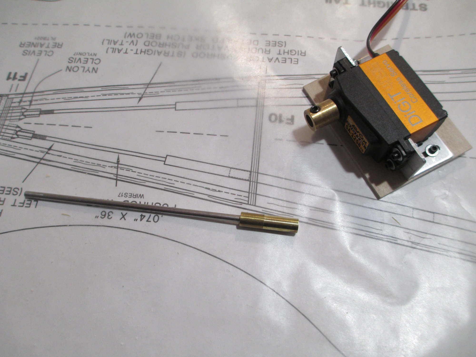
This is the driveshaft separated from the coupler. The driveshaft is made using a 1/8" stainless rod pressed into a 1/4" diameter brass end that slides into the coupler and locked in place with a set screw.
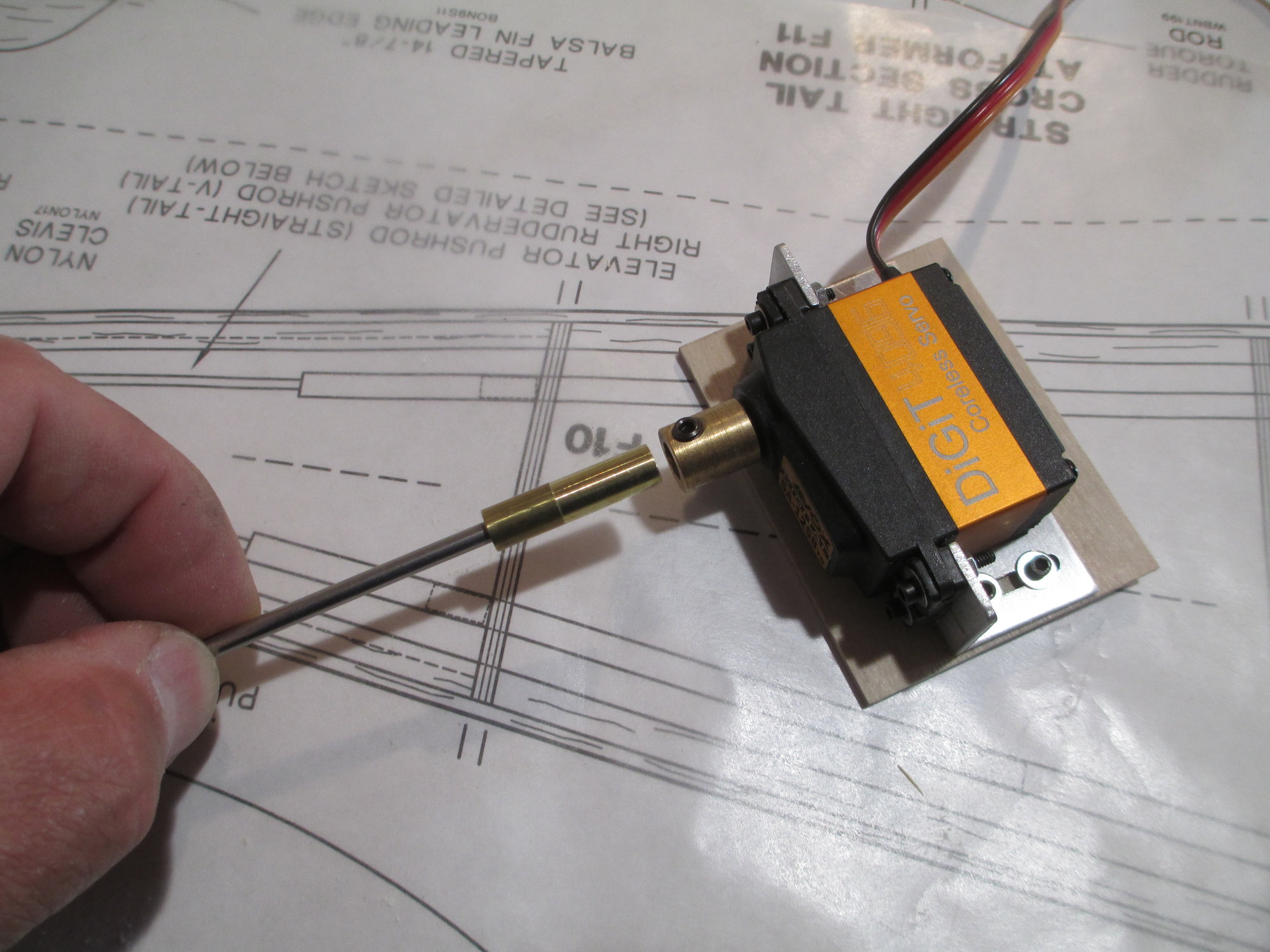
Once the drive shaft is inserted into the coupler, it is locked into position with a set screw. Once I determine the exact spot where the driveshaft is in relation with the coupler, I will grind a flat spot which will prevent the drive shaft from rotating inside of the coupler.
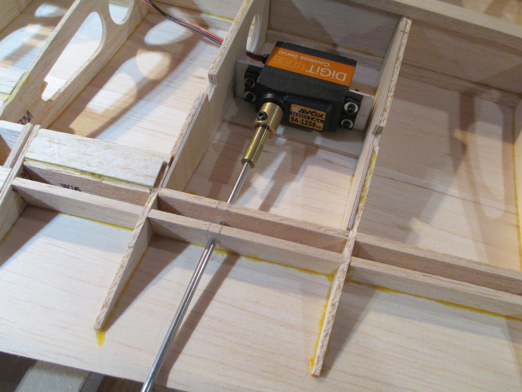
With the servo now in position, you can see where the drive shaft exits is right on the mark!
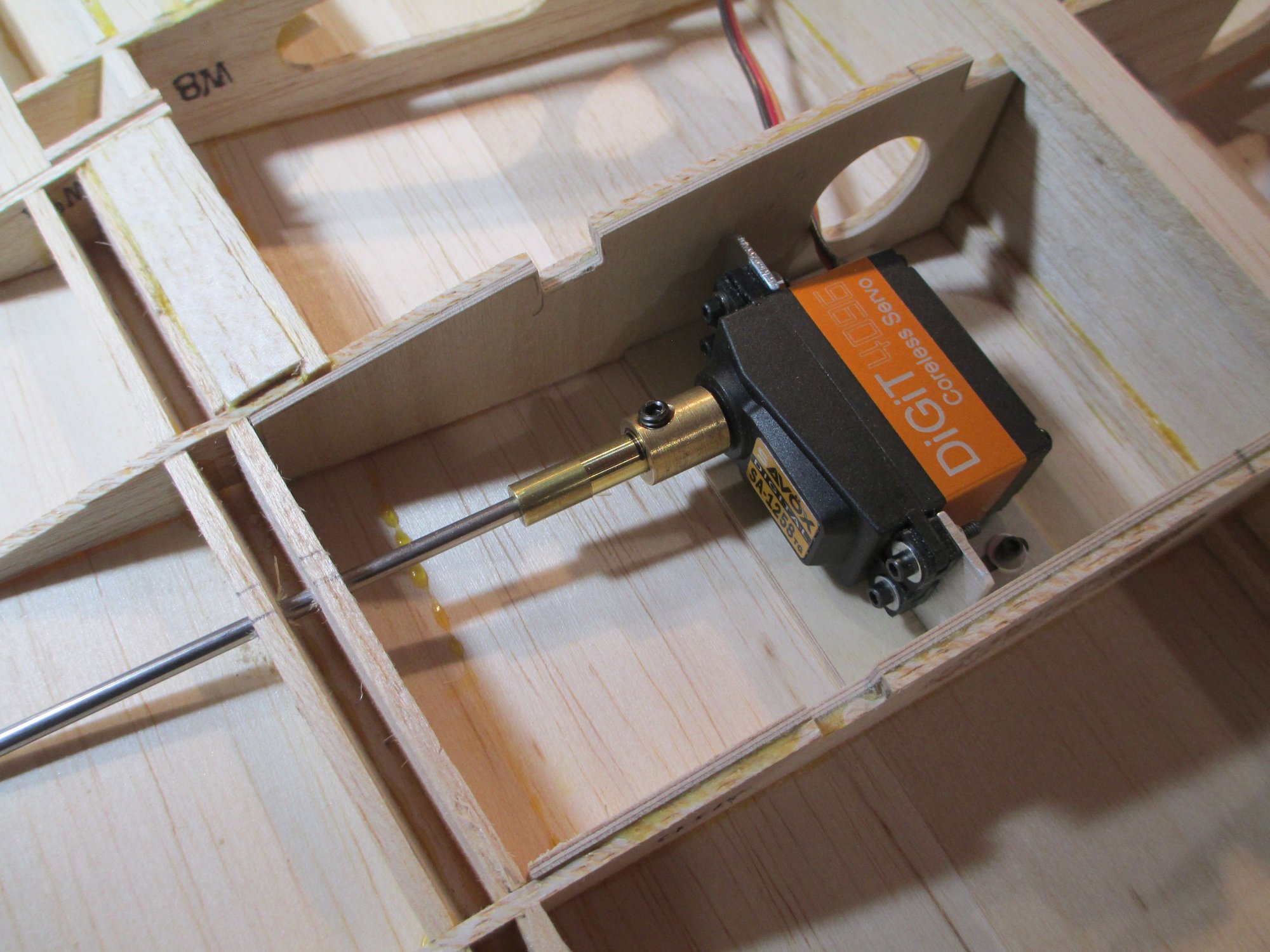
I need the epoxy to cure then I can separate the servo from the bracket and remove the drive shaft.
Last edited by VincentJ; 09-10-2019 at 04:36 AM.