


F-16XL ARF by Global Knight Models from Global Jet Club
 04-14-2021, 05:46 PM
#126

Thread Starter
My Feedback: (20)
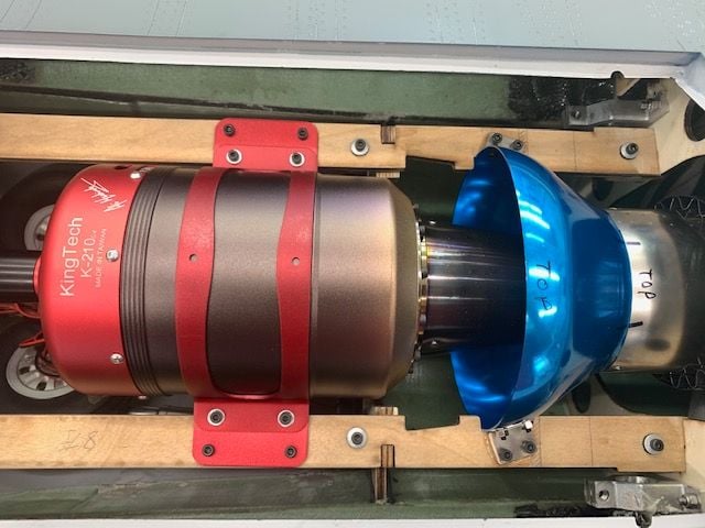
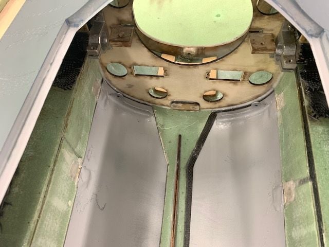
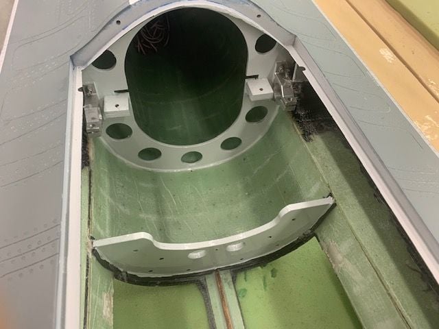
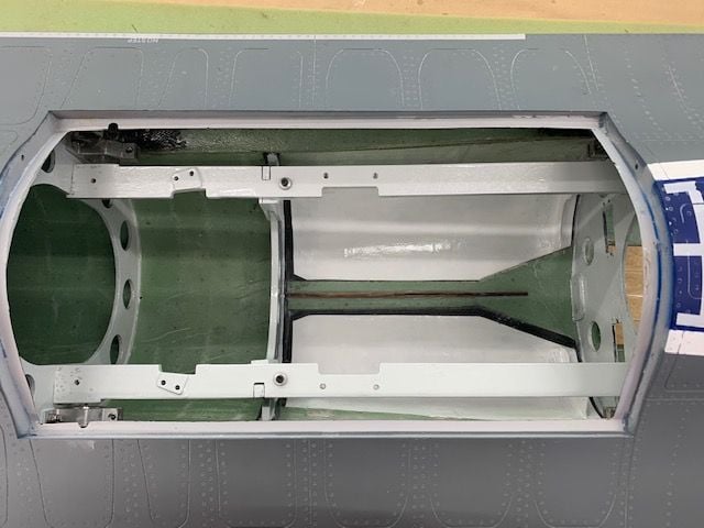
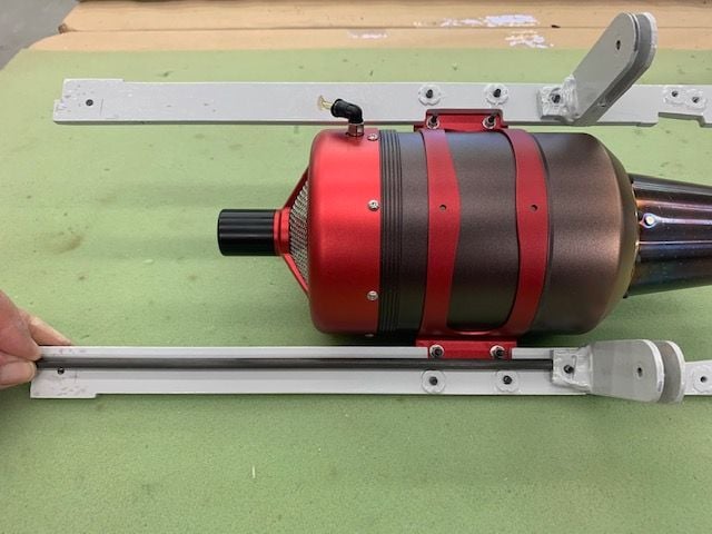
Mounting turbine and pipe
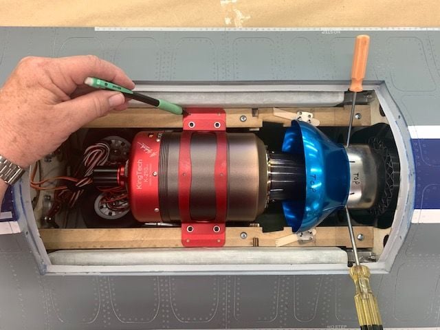
Dry fit of turbine and pipe. Rails tacked down with supplied wood screws. Pipe had to be shimmed up slightly to center on turbine. Punches holding bell on pipe during fitting. Mounts and holes marked for drilling.
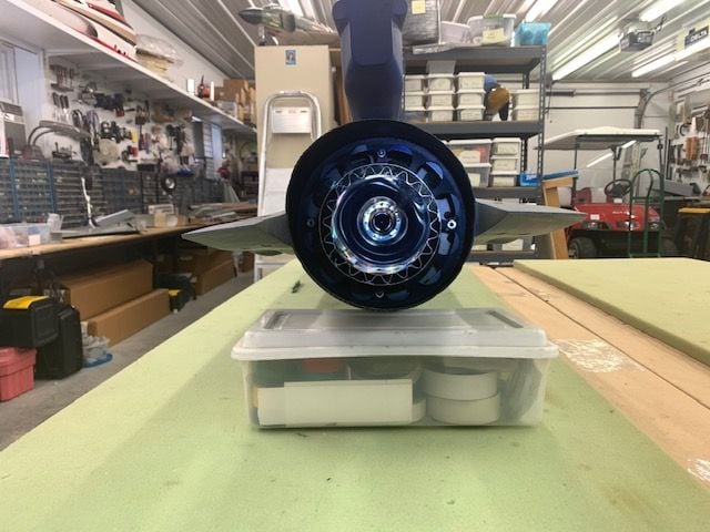
Turbine looks pretty close here
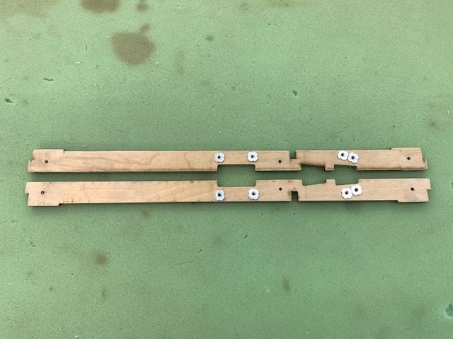
Drilled holes and installed 6-32 blind nuts
Bolt fitting test. For once I drilled them all in the right place!
I went back and replaced all the wood screws on the rails with 6-32 bolts and blind nuts.
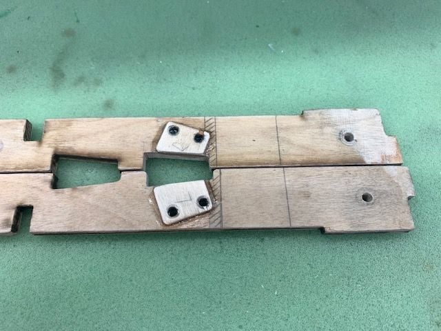
Plywood shims for pipe glued on rails
Forward rail blind nuts are on top. Bolts are accessed from gear doors.
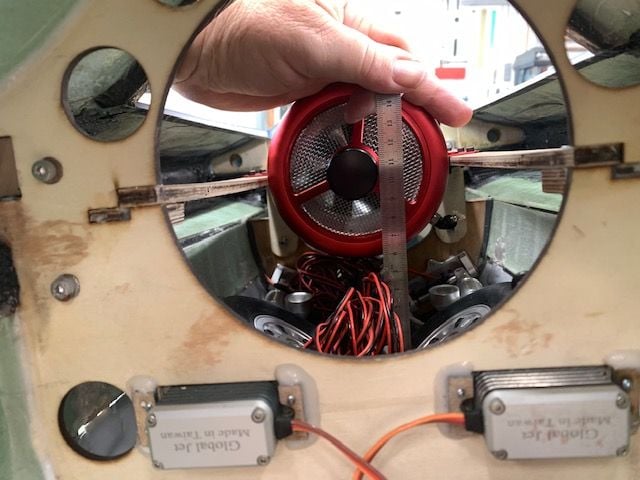
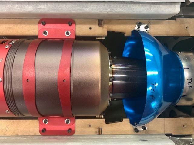
After mounting the turbine, I was concerned about the long thin rails bending. I found that the front of the turbine would flex up and down 3-4 mm due to the rails bending in the middle.
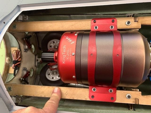
This is where the bending occurs right in the middle between the front and mid mounts.
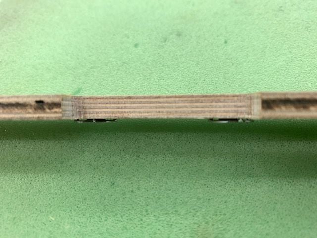
The rails look like good quality 9 ply plywood but they still flex more than I would like. I would recommend doubling the thickness of the rails because they are so long and narrow.
With the on and off of the nozzle fitting the pipe the rear plywood former started to delaminate where the wood screws attach. I treated them with thin CA to harden the screw holes but I am thinking about adding blind nuts and bolts since this is what holds the rear pipe i place. Maybe a key lock slot to twist lock the nozzle would help maintain the integrity of the plywood former.
Dry fit of turbine and pipe. Rails tacked down with supplied wood screws. Pipe had to be shimmed up slightly to center on turbine. Punches holding bell on pipe during fitting. Mounts and holes marked for drilling.
Turbine looks pretty close here
Drilled holes and installed 6-32 blind nuts
Bolt fitting test. For once I drilled them all in the right place!
I went back and replaced all the wood screws on the rails with 6-32 bolts and blind nuts.
Plywood shims for pipe glued on rails
Forward rail blind nuts are on top. Bolts are accessed from gear doors.
After mounting the turbine, I was concerned about the long thin rails bending. I found that the front of the turbine would flex up and down 3-4 mm due to the rails bending in the middle.
This is where the bending occurs right in the middle between the front and mid mounts.
The rails look like good quality 9 ply plywood but they still flex more than I would like. I would recommend doubling the thickness of the rails because they are so long and narrow.
With the on and off of the nozzle fitting the pipe the rear plywood former started to delaminate where the wood screws attach. I treated them with thin CA to harden the screw holes but I am thinking about adding blind nuts and bolts since this is what holds the rear pipe i place. Maybe a key lock slot to twist lock the nozzle would help maintain the integrity of the plywood former.
 04-14-2021, 06:02 PM
#127
Thread Starter
My Feedback: (20)
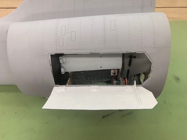
Removed the main landing gear
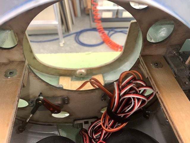
I did not like the way the gear came installed where the wires were wrapped through the subformer.
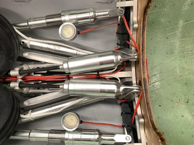
This did not look good to me plus I had no idea of which wire was what since nothing was labeled and there are no plug on 4 of the 6 the wires. I did figure out the gear motors had plugs that fit into the controller.
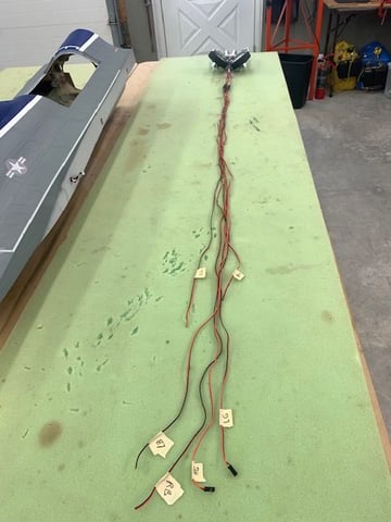
I took out the gear. It was the easiest removal of any F-16 gear I've done since it comes out the top hatch and you do not have to thread it through the gear doors. I clipped all the factory zip ties and then figured out what each wire was and made temporary labels.
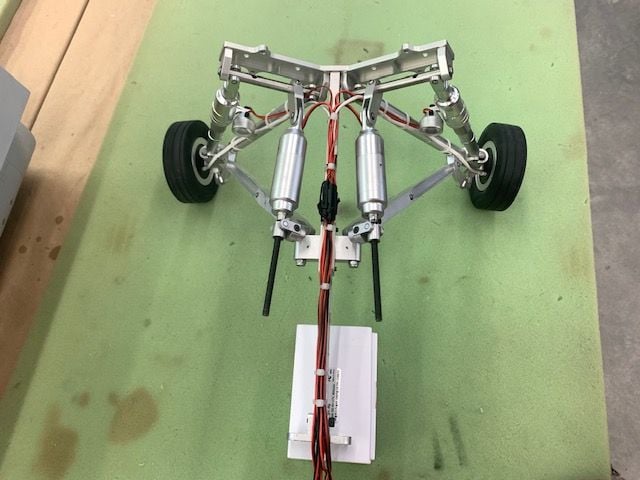
I re routed the wiring to make all the wires run forward. Looks much better. The electric gear motors are very smooth and quiet. The gear looks really nice and strong.
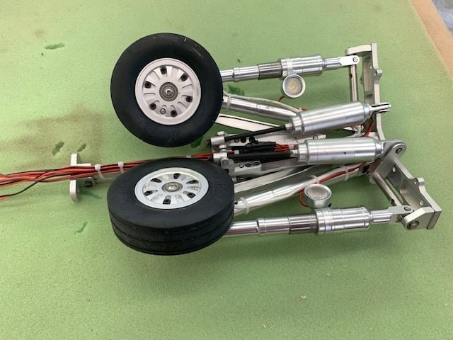
Ready to reinstall
I went ahead and removed the door servos. I plan paint the bare wood formers to fuel proof and make them look better.
I will also paint the inside of the gear doors white like the inside of F-16 gear wells.
I did not like the way the gear came installed where the wires were wrapped through the subformer.
This did not look good to me plus I had no idea of which wire was what since nothing was labeled and there are no plug on 4 of the 6 the wires. I did figure out the gear motors had plugs that fit into the controller.
I took out the gear. It was the easiest removal of any F-16 gear I've done since it comes out the top hatch and you do not have to thread it through the gear doors. I clipped all the factory zip ties and then figured out what each wire was and made temporary labels.
I re routed the wiring to make all the wires run forward. Looks much better. The electric gear motors are very smooth and quiet. The gear looks really nice and strong.
Ready to reinstall
I went ahead and removed the door servos. I plan paint the bare wood formers to fuel proof and make them look better.
I will also paint the inside of the gear doors white like the inside of F-16 gear wells.
Last edited by Viper1GJ; 04-15-2021 at 04:41 PM.

The following users liked this post:
Viper1GJ (04-15-2021)
04-15-2021, 04:58 PM
#129
Thread Starter
My Feedback: (20)
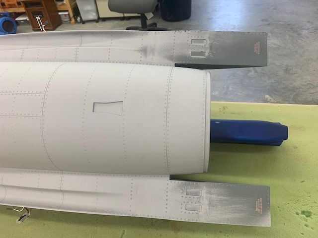
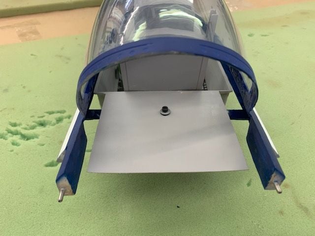
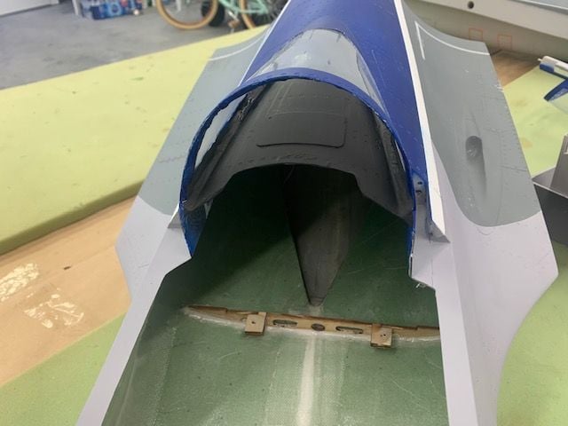
Nozzle upgrade

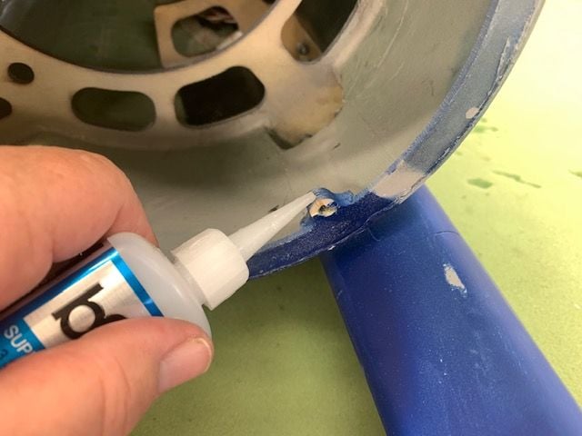
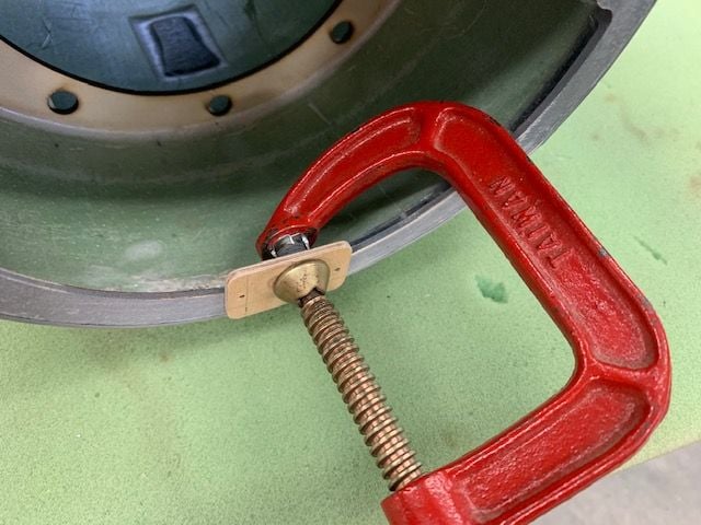
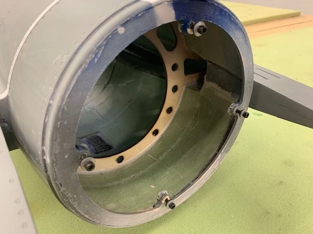
The rear fuse former that holds the nozzle on delaminated on two of the tabs where the wood screws go in to hold on the nozzle. The tabs need to be larger to prevent he chipping of the surface ply. I decided to add blind nuts and use bolts to hold on the nozzle. I would recommend a key hole slot and twist lock system to hold on the nozzle. It makes much easier to mount the nozzle when installing or removing the pipe and LED AB ring.
 \
\
C clamp used to pull blind nuts into the wood.
Blind nuts secured with medium CA and bolts inserted. I'm using bonded sealing washers on the bolts.
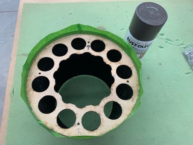
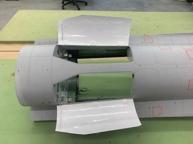
The nozzle former was only partially painted inside the nozzle so I decided to redecorate it a little.
Front side of the former painted to seal the wood
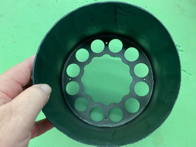
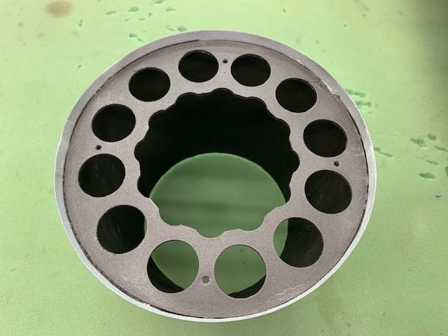
Aft end repainted to get all the wood covered.
The rear fuse former that holds the nozzle on delaminated on two of the tabs where the wood screws go in to hold on the nozzle. The tabs need to be larger to prevent he chipping of the surface ply. I decided to add blind nuts and use bolts to hold on the nozzle. I would recommend a key hole slot and twist lock system to hold on the nozzle. It makes much easier to mount the nozzle when installing or removing the pipe and LED AB ring.
\C clamp used to pull blind nuts into the wood.
Blind nuts secured with medium CA and bolts inserted. I'm using bonded sealing washers on the bolts.
The nozzle former was only partially painted inside the nozzle so I decided to redecorate it a little.
Front side of the former painted to seal the wood
Aft end repainted to get all the wood covered.
04-15-2021, 05:20 PM
#130
Join Date: Mar 2009
Location: willow springs , IL
Posts: 1,216
Likes: 0
Received 25 Likes
on
14 Posts
Maybe to stiffen the engine rails glue 1/8" aircraft ply vertically to the outside of the rail. I think it would save some weight and really stiffen it turning the rail into an L.
04-15-2021, 05:24 PM
#131
Thread Starter
My Feedback: (20)
Fuel proofing and decorating the inside
Not sure what happened in the factory paint shop here but I just saw this today. It looks like a lot of overspray when painting the top darker grey color. It appears as if the spray gun was pointing at the trailing edge of the wing and speedbrakes at a low angle and shot paint on underside of the speedbrake panels. Then the decals were placed on top of the overspray.
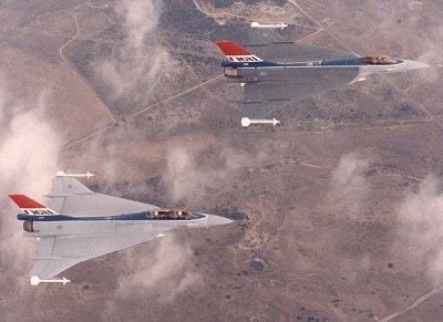
Painted inside the nose gear door white like the F-16 XL prototype scheme. Had some left over light grey so I painted the nose gear mounting plate just for fun. I used KlassKote epoxy paint for both colors.

Inside of nose gear door painted white
Inside of main gear doors painted white
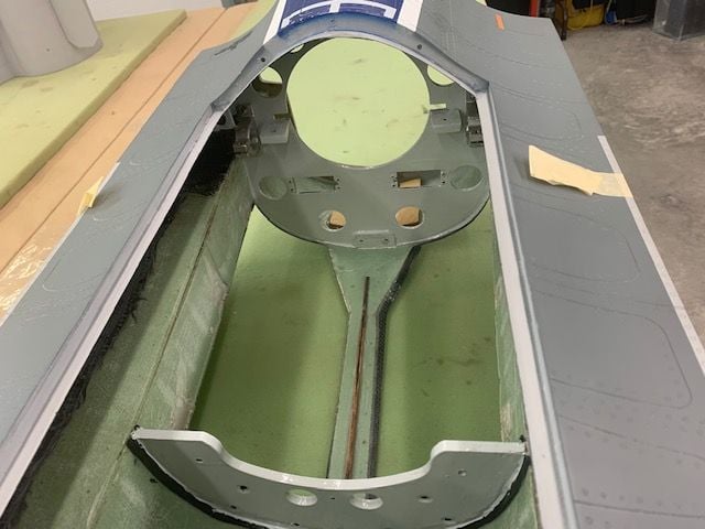
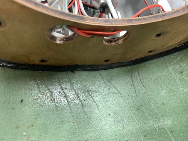
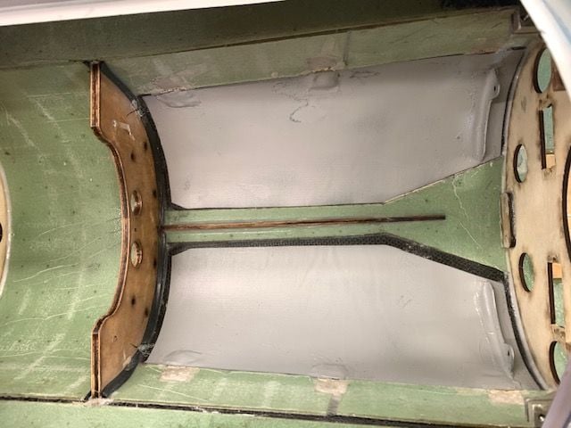
Front former. I like to seal the wood parts before they get exposed to fuel and oil. The main gear sub former had some kind of sealer on it already but the front and rear formers were bare wood.
Rear former. I wanted the inside to look good when the lid is off so the turbine mounting rails and brackets were also painted to make everything match.
Not sure what happened in the factory paint shop here but I just saw this today. It looks like a lot of overspray when painting the top darker grey color. It appears as if the spray gun was pointing at the trailing edge of the wing and speedbrakes at a low angle and shot paint on underside of the speedbrake panels. Then the decals were placed on top of the overspray.
Painted inside the nose gear door white like the F-16 XL prototype scheme. Had some left over light grey so I painted the nose gear mounting plate just for fun. I used KlassKote epoxy paint for both colors.
Inside of nose gear door painted white
Inside of main gear doors painted white
Front former. I like to seal the wood parts before they get exposed to fuel and oil. The main gear sub former had some kind of sealer on it already but the front and rear formers were bare wood.
Rear former. I wanted the inside to look good when the lid is off so the turbine mounting rails and brackets were also painted to make everything match.
Last edited by Viper1GJ; 04-15-2021 at 05:36 PM.


 04-16-2021, 04:36 PM
#133
Thread Starter
My Feedback: (20)
Turbine rail test fit after paint. Had to lightly sand some of the slots but it worked ok.
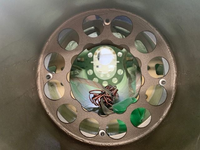
Nozzle install test with bolts and blind nuts. A twist lock with key slots would be much easier. This will be a little harder with the pipe installed.
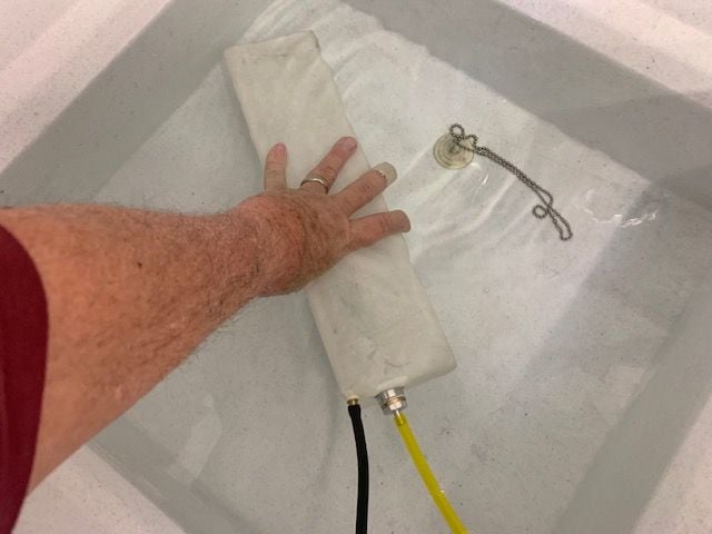
Finally got around to leak testing the fuel tanks.
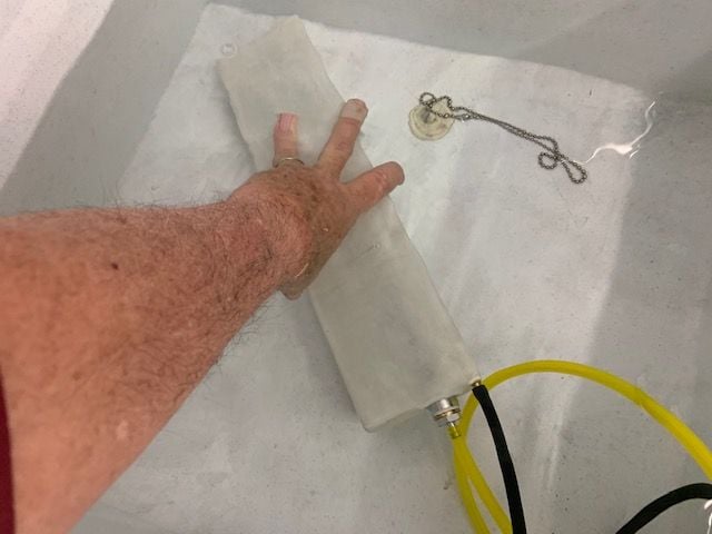
I'm at the other end of the tubing with puffed cheeks and red face.
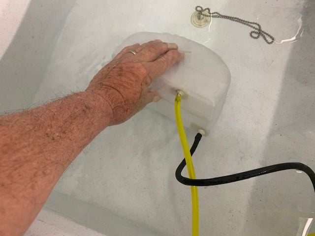
All three tanks passed with no bubbles. All good.
04-16-2021, 04:52 PM
#134
Thread Starter
My Feedback: (20)
Stiffening the turbine rails.
Jofunk, thanks for the suggestion. I had been thinking about ways to stiffen the rails when I read your suggestion. I then thought of using carbon rods the same way as the vertical ply strip. Thanks for triggering my brain
Testing to see if the carbon rod would clear all the clamp bolts and blind nuts. Looks like a good fit except for the blind nut flanges.
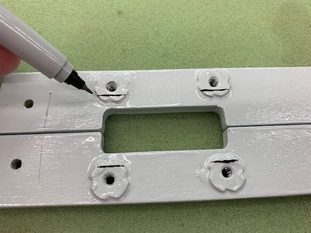
Blind nut flanges marked for removal
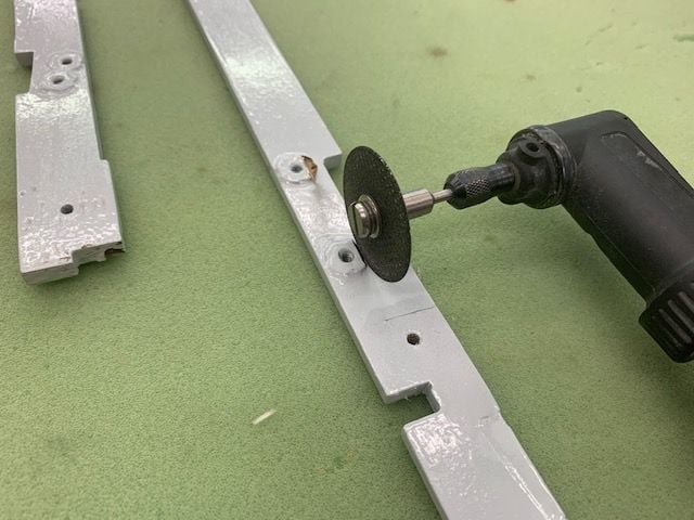
Cutoff wheel used to remove flanges
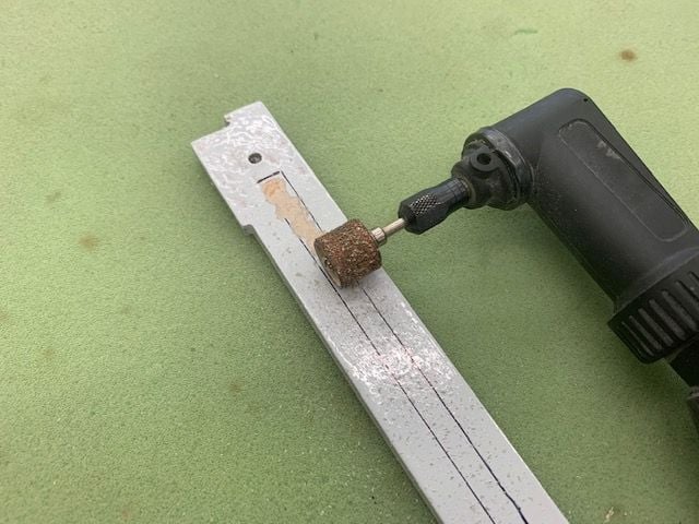
Paint removed with sanding wheel
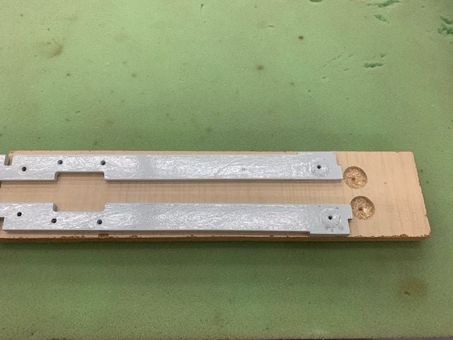
The rails had a slight natural bend in opposite directions so I made a gluing jig to keep them flat during epoxy cure. The relief holes cut to allow the blind nuts to be recessed below the surface
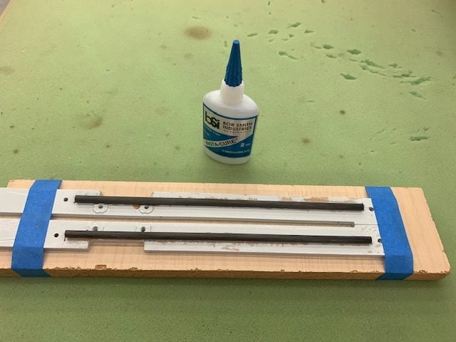
Rails taped to jig and carbon rods tacked in place with thin CA
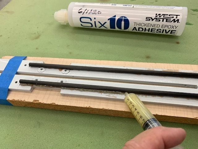
Bead of Six10 epoxy laid along each side of the rods
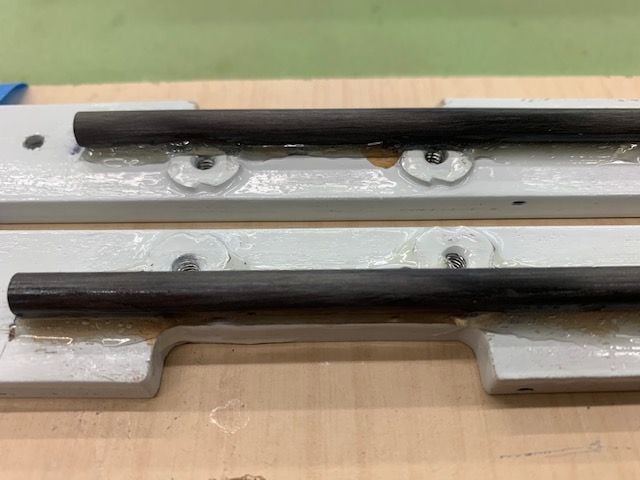
Finger fillet tool used to smooth the epoxy and squeeze it under the tubes. Left for overnight cure.
Testing to see if the carbon rod would clear all the clamp bolts and blind nuts. Looks like a good fit except for the blind nut flanges.
Blind nut flanges marked for removal
Cutoff wheel used to remove flanges
Paint removed with sanding wheel
The rails had a slight natural bend in opposite directions so I made a gluing jig to keep them flat during epoxy cure. The relief holes cut to allow the blind nuts to be recessed below the surface
Rails taped to jig and carbon rods tacked in place with thin CA
Bead of Six10 epoxy laid along each side of the rods
Finger fillet tool used to smooth the epoxy and squeeze it under the tubes. Left for overnight cure.
Last edited by Viper1GJ; 04-16-2021 at 05:37 PM.
04-16-2021, 05:34 PM
#135
Thread Starter
My Feedback: (20)
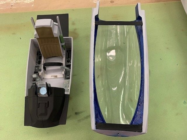
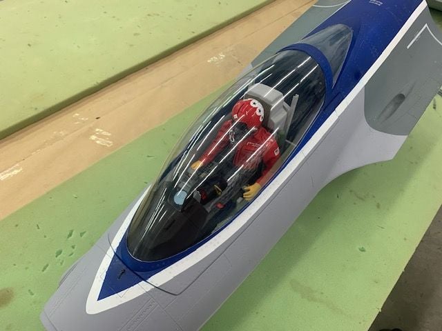
Installing pilot, cockpit, and canopy
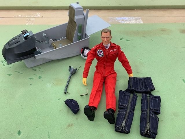
I unboxed my long forgotten pilot. Looks like he survived 21 years in deep hibernation on the cabinet top shelf OK. This build has now driven me to start paying with dolls!
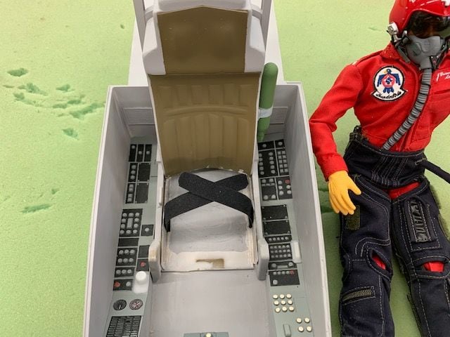
Had to remove the fiberglass seat cushion to get the pilot seating height to where canopy would fit. I cut 2 slots cut for thin Velcro One Wrap seat belt
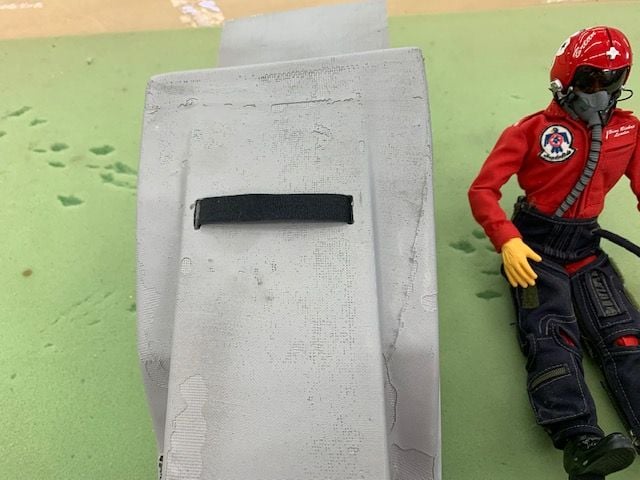
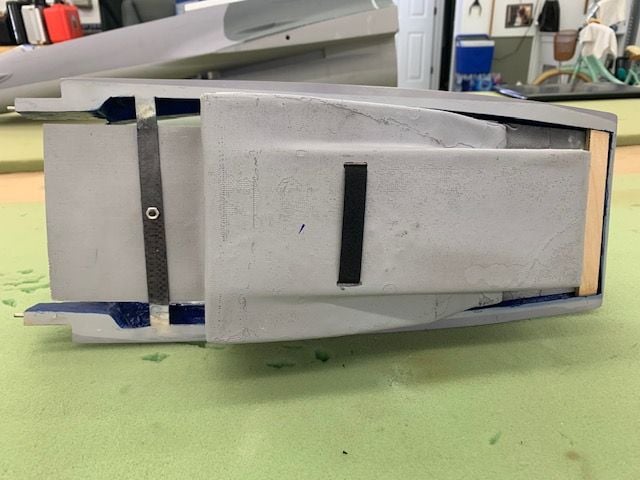
Seat belt loops under cockpit tub
Here's where the fun starts. The cockpit tub does not fit the cockpit opening in the fuse. It just falls in. The cockpit tub does not fit the canopy. It just fall out. So you have to improvise an scratch built system to fix it either way. The build guide recommends building wood braces in fuse to hold in the cockpit tub. This would interfere with getting the equipment tray in and out of the fuse. Josh recommended to hot glue the tub into the canopy.
I did not want to glue it in because I always have to fix something so I figured a way to attach the tub using one screw. A plywood strip was glued across the front of the cockpit to act as a retaining lip in the front. The rear of the tub is inserted over the rear canopy brace and then the front of the instrument panel is inserted over the plywood lip. Then the bolt is secured to hold the cockpit tub into the canopy frame.
Global Knight needs to fix this. An ARF Pro at this price point should not need to have the cockpit installation have to be scratch built. It needs to fit correctly as delivered.
Single bolt holds cockpit tub into the canopy frame
Cockpit parts painted black
The deck under the aft canopy should be black not blue.

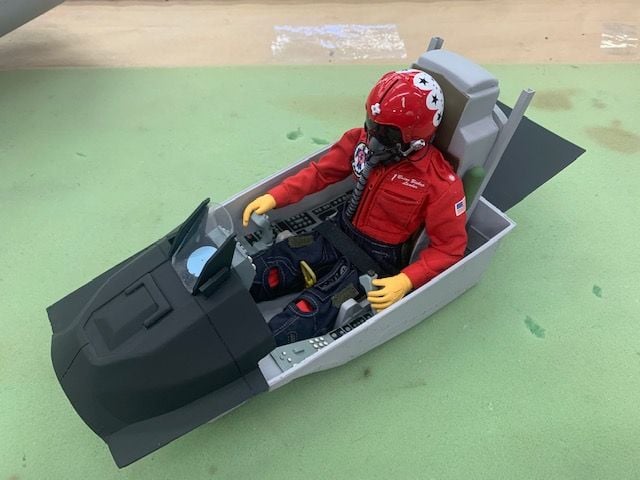
Cockpit tub and pilot ready to install. This guy is either brave or stupid or both. He has no chute harness. I always said about the Aces II ejection seat that it was "Thrust you can trust!"
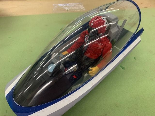
Ready to fly.
Installed in fuse
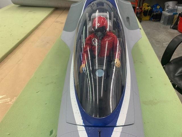
Ready to rock and roll!
I unboxed my long forgotten pilot. Looks like he survived 21 years in deep hibernation on the cabinet top shelf OK. This build has now driven me to start paying with dolls!
Had to remove the fiberglass seat cushion to get the pilot seating height to where canopy would fit. I cut 2 slots cut for thin Velcro One Wrap seat belt
Seat belt loops under cockpit tub
Here's where the fun starts. The cockpit tub does not fit the cockpit opening in the fuse. It just falls in. The cockpit tub does not fit the canopy. It just fall out. So you have to improvise an scratch built system to fix it either way. The build guide recommends building wood braces in fuse to hold in the cockpit tub. This would interfere with getting the equipment tray in and out of the fuse. Josh recommended to hot glue the tub into the canopy.
I did not want to glue it in because I always have to fix something so I figured a way to attach the tub using one screw. A plywood strip was glued across the front of the cockpit to act as a retaining lip in the front. The rear of the tub is inserted over the rear canopy brace and then the front of the instrument panel is inserted over the plywood lip. Then the bolt is secured to hold the cockpit tub into the canopy frame.
Global Knight needs to fix this. An ARF Pro at this price point should not need to have the cockpit installation have to be scratch built. It needs to fit correctly as delivered.
Single bolt holds cockpit tub into the canopy frame
Cockpit parts painted black
The deck under the aft canopy should be black not blue.
Cockpit tub and pilot ready to install. This guy is either brave or stupid or both. He has no chute harness. I always said about the Aces II ejection seat that it was "Thrust you can trust!"
Ready to fly.
Installed in fuse
Ready to rock and roll!
Last edited by Viper1GJ; 04-16-2021 at 05:43 PM.
The following users liked this post:
yeahbaby (04-16-2021)
The following users liked this post:
Viper1GJ (04-18-2021)
04-21-2021, 02:42 PM
#139
Thread Starter
My Feedback: (20)
RC hookup and programming
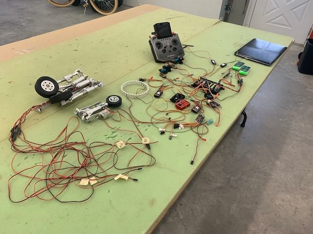
I spent the weekend and Monday getting this mess working. Everything connected and worked OK except the Cortex Pro gyro. I spent a full day troubleshooting, swapping parts, wires, switches etc and still could not get the gyro to accept the axis teach in process and gyro control channel. After verifying all the parts would work on another model it came down to the model file. It turned out that the model file I copied from my 1/5 F-16 got corrupted in the process somehow and would not send the Cortex Pro what it needed even though it looked like it did. I created another model file from scratch and it worked perfectly the first try. Lesson learned is don't copy a complex model file, make changes, and expect it to always work correctly. Everything works now. The landing gear works really well and the AB LED ring looks really cool. Now to get all this stuffed back in the jet.
Many thanks to Danny at AeroPanda for helping me figure out the problem. I can't say enough good about the customer support from AeroPanda.
That's all this week. Packing the camper today for the SC Jet Together at Flying TIger field this weekend. To be continued....
Gary
The following users liked this post:
Viper1GJ (04-23-2021)
04-23-2021, 03:35 PM
#141
Hi Gary,
I see that you shimmed up slightly the pipe to center the turbine. Aren�t you changing the thrust angle by doing that? I guess is neglible but I usually never change the pipe mount or at least check the angle before to adjust it if necessary.
I see that you shimmed up slightly the pipe to center the turbine. Aren�t you changing the thrust angle by doing that? I guess is neglible but I usually never change the pipe mount or at least check the angle before to adjust it if necessary.
04-23-2021, 05:16 PM
#142
Thread Starter
My Feedback: (20)
Gary
04-24-2021, 06:16 AM
#143
Guess what showed up? I will post some photos later. I have been following this since you started your build. Two quick questions, 1) where is the GC, what would be a good starting point. I saw the picture of the scales and could calculate the ARM but it would be nice to have a reference point. Next very important question. 2) how tall the pilot guy? 10 inch one? got to get one on order.
Thanks
Terry G
I am so "junior" that I cannot post pictures
Thanks
Terry G
I am so "junior" that I cannot post pictures
Last edited by tmgreen64; 04-24-2021 at 06:23 AM.
04-24-2021, 12:07 PM
#145
Thread Starter
My Feedback: (20)
Pilot size and CG
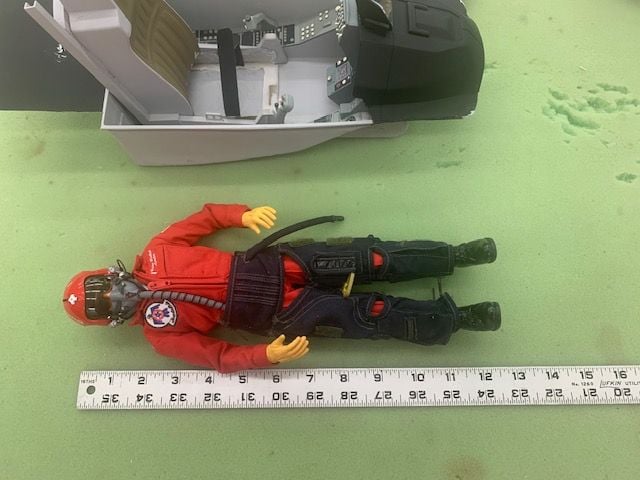
My pilot is 12"
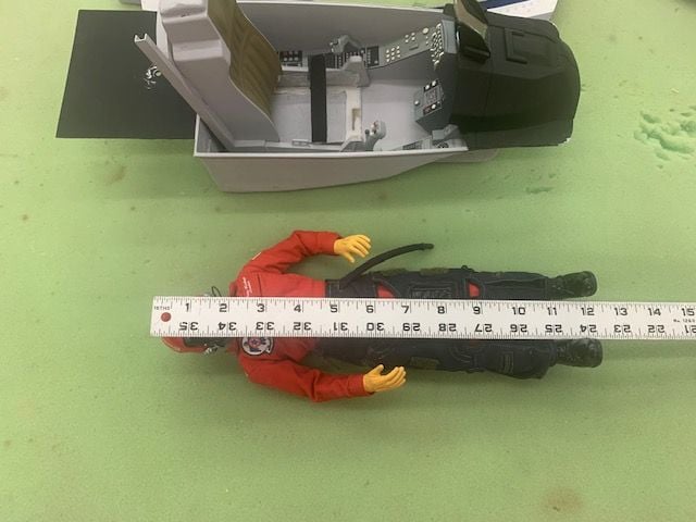
I had to cut out the seat to get it to fit but it looks about right in scale.
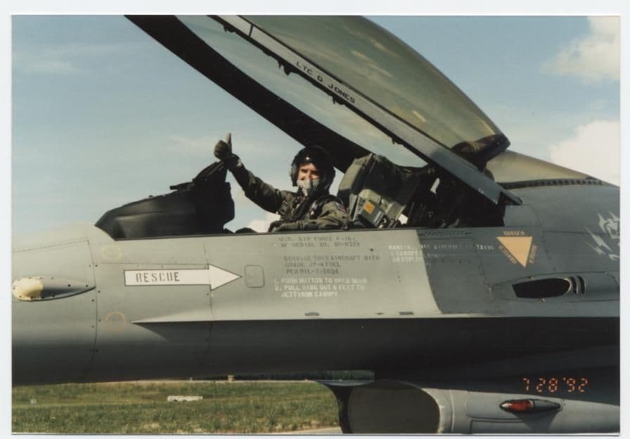
Here the picture I used to get the seating height. It's a picture of an F-16 pilot I used to know. At seating height the top of his helmet is about at the top of the ejection seat.
Top of helmet is about level with top of ejection seat here and the canopy clears the helmet.
Terry,
Contact Mike Lin at Global Jet Club to get the PDF build guide by email. It has recommended CG info.
I think I read somewhere here on RCU you had to post 10 times to post pictures. Not sure if this correct or not. Looking forward to seeing your pictures.
Gary
...Two quick questions, 1) where is the GC, what would be a good starting point. I saw the picture of the scales and could calculate the ARM but it would be nice to have a reference point. Next very important question. 2) how tall the pilot guy? 10 inch one? got to get one on order. Thanks
Terry G
I am so "junior" that I cannot post pictures
Terry G
I am so "junior" that I cannot post pictures
My pilot is 12"
I had to cut out the seat to get it to fit but it looks about right in scale.
Here the picture I used to get the seating height. It's a picture of an F-16 pilot I used to know. At seating height the top of his helmet is about at the top of the ejection seat.
Top of helmet is about level with top of ejection seat here and the canopy clears the helmet.
Terry,
Contact Mike Lin at Global Jet Club to get the PDF build guide by email. It has recommended CG info.
I think I read somewhere here on RCU you had to post 10 times to post pictures. Not sure if this correct or not. Looking forward to seeing your pictures.
Gary
04-24-2021, 12:24 PM
#146
Gary, thanks this is post #2, 8 more to go. I will email Mike about the PDF, I have an fuel tank from a Aspire that is a little bigger than the one you made, I plan on cutting it and making it smaller to fit in the XL. I will take photos and when able post them.
I am going to get my pilot dude on order.
Thanks
Terry
I am going to get my pilot dude on order.
Thanks
Terry
04-24-2021, 04:44 PM
#147
My Feedback: (2)
I flew the manual GC with .4lbs nose heavy and in turns the nose would want to climb and you have to be on the power. As the fuel tanks emptied it got worse. My batteries are probably too far aft (behind the cockpit) I will put them closer to the nose section and adjust accordingly.
Josh's XL is quite nose heavy but his jet seems to like that as you can see in the videos.
Josh's XL is quite nose heavy but his jet seems to like that as you can see in the videos.
04-24-2021, 04:52 PM
#148
I flew the manual GC with .4lbs nose heavy and in turns the nose would want to climb and you have to be on the power. As the fuel tanks emptied it got worse. My batteries are probably too far aft (behind the cockpit) I will put them closer to the nose section and adjust accordingly.
Josh's XL is quite nose heavy but his jet seems to like that as you can see in the videos.
Josh's XL is quite nose heavy but his jet seems to like that as you can see in the videos.
Tg
04-26-2021, 01:46 PM
#150
A friend came over to look at the LX, He is a great builder. Has some suggestions, one was relocating the main gear door servos so the tank up front can be bigger, another was to put some carbon fiber on the back of the bulkhead that the wing clamps are bolted to, this would spread.
the load. We may repaint the blue and red and sharpen up the white line. when I get started I will post some pictures, still have about 6 more post to do before I am able. Looking forward to starting
Terry g
the load. We may repaint the blue and red and sharpen up the white line. when I get started I will post some pictures, still have about 6 more post to do before I am able. Looking forward to starting
Terry g