


Vortex F3A build thread
 06-14-2019 | 09:07 AM
#1
Thread Starter

I started this project 2 years ago and for a while i managed to make some good progress; all major components were built and ready for film covering. The initial plan was to finish the model, test it and improve it as much as possible before releasing the drawings.
Unfortunately sometimes real life gets in the way of our projects and at the moment it seems there will be a long while before I will be able to work on this again. I would hate to see all the work go to waste though, so I decided to publish the drawings anyway and maybe others will enjoy building and flying this model. I tried to use all the experience gathered with my previous designs and all my flight testing observations to make Vortex a great flying model, but of course since the prototype is not finished yet i can't make any claims about its flight performance.
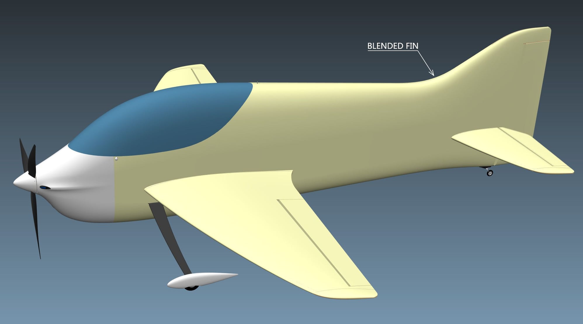
My prototype has a more complex fin that blends into the fuselage; this may look nice but it takes some time and effort to build. That�s why I designed another version with a simplified fin and the builder can decide which version he prefers.
So the main 2 versions of Vortex are Blended Fin (BF) and Simplified Fin (SF); the drawings for these 2 versions are completely separate so there is no risk for confusion. Each of these 2 versions has a number of options, depending on the type of motor you plan to use (front mounted or back mounted).
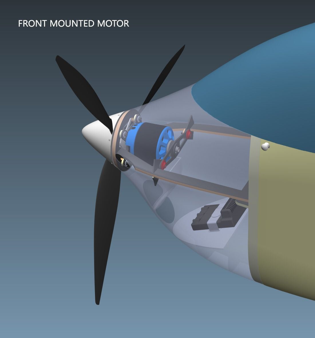
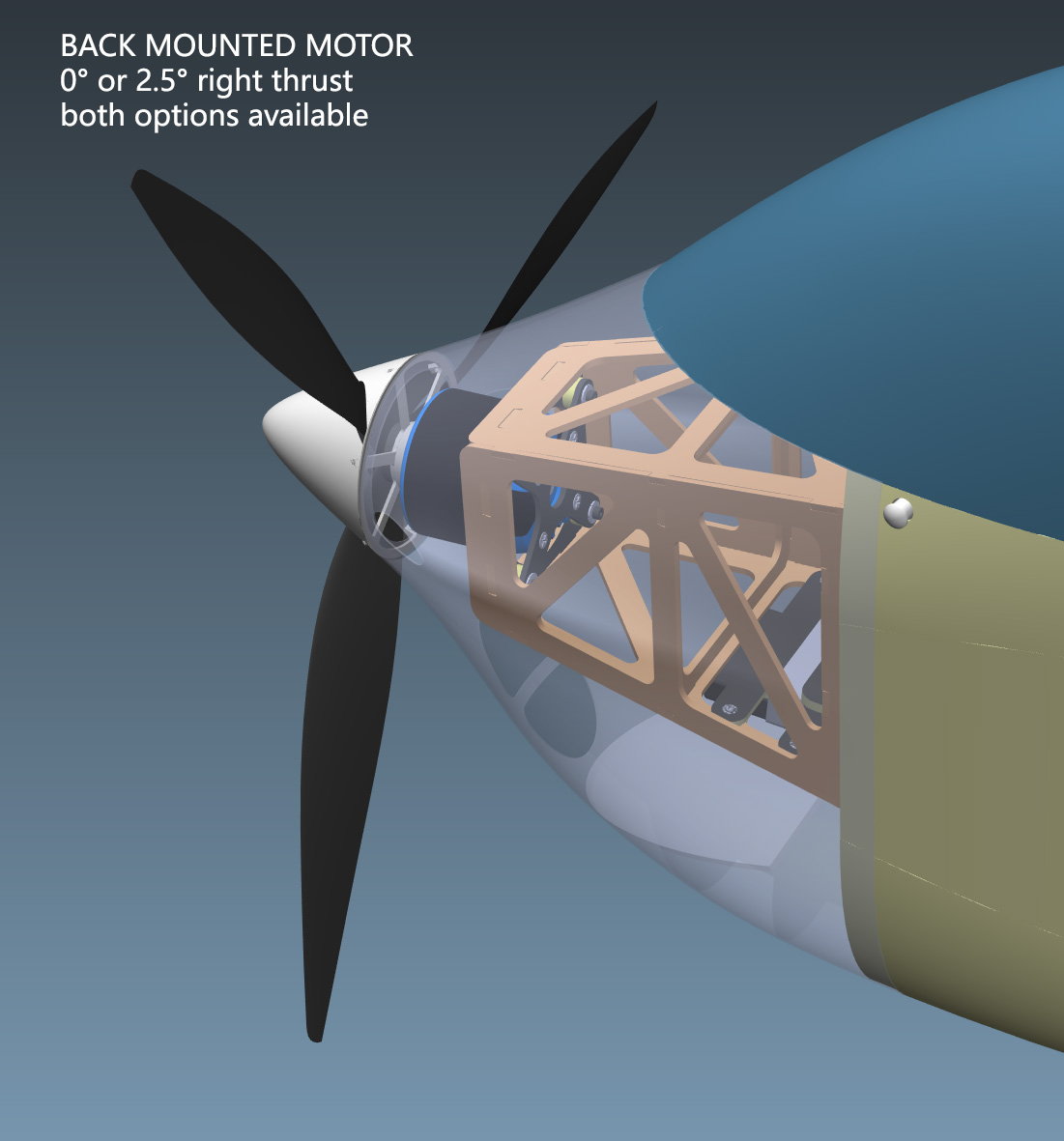
For the front mounted motors the fixation points are very close to the spinner, so it�s easy to adjust the right thrust angle by shimming the motor, from 0 to at least 3 degrees. For the back mounted motors it�s a little more difficult, so I included 2 different motor mounts, one with 0 degrees right thrust (if you plan to use a setup similar to the Allure / Alchemy) and one with 2.5 degrees right thrust.
The cowl will be 5mm longer than needed at the front, so you can cut them according to your preferred right thrust angle or for slightly different spinner sizes. I would recommend leaving the nose a little longer, and you can trim it after the first flights when the thrust angle is set.
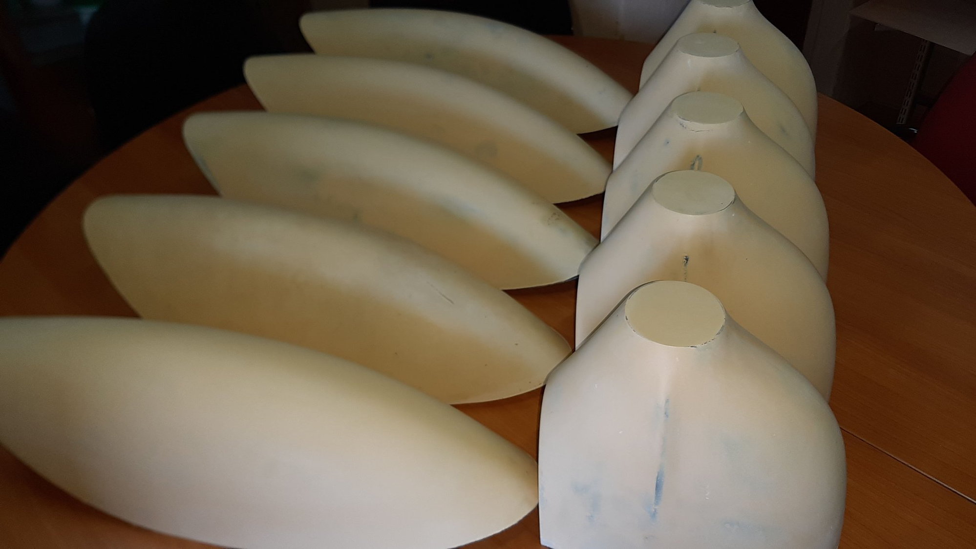
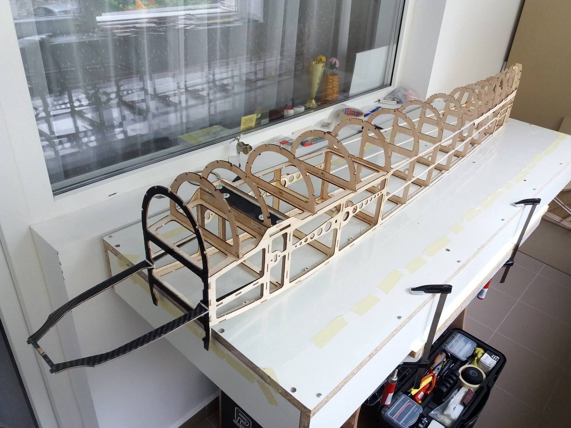
The pictures may not reveal the true dimensions of this model but Vortex is a VERY large plane: the fuselage is almost half a meter tall in the canopy area (480mm to be more exact) and the fin is 563mm. Of course when building a plane of this size you need to be very careful with the materials selection, so you should use only contest grade balsa. I used 100 kg/m3 density balsa which is far from the lightest but I think the final weight will be under 5Kg with film covering.
The drawings are structured in folders depending on the material type and the required sheet dimensions are included in the file names. You will notice that some balsa sheets dimensions are 500x200mm which means they are made of two 100 mm wide sheets glued together before laser cutting.
The file format is DWG and there are 2 main layers on each drawing: one named �Cutting� (red color) and one named �Marking� (green color, used only for engraving part codes and other useful marks).
All the major structural parts are found inside the �Laser Cutting Files� folder - I do not recommend cutting these parts on a CNC router! To ensure proper interlocking between parts, I used a small offset to compensate for the width of the laser beam. This offset is quite small for soft balsa or liteply parts (0.15mm) but it can be double for tough materials like the 3mm hard plywood. If you use a CNC router, you will have to sand off this small offset to make the parts fit.
In the �CNC cutting files� folder you will find all the materials that are impossible to cut by laser. The parts in this folder are mostly accessories like control horns, ESC support, battery tray, motor X mounts, etc. You can of course choose to cut these by hand or change the materials if you wish.
If you wish to download the drawings please follow the links below and click the download icon (small arrow at the top right corner of the screen). I will add pictures of the building process here on the forum so you have something to guide you and I will do my best to support you if you need any advice or more information.
Vortex F3A BF � blended fin version:
https://drive.google.com/�/1QYhsgJMIUQnEe71J8_UnipDOg_C4KDNe
Vortex F3A SF � simplified fin version:
https://drive.google.com/�/1lZ0lNyZL-c27EtNUiYrh8-5Cky374BtO


Unfortunately sometimes real life gets in the way of our projects and at the moment it seems there will be a long while before I will be able to work on this again. I would hate to see all the work go to waste though, so I decided to publish the drawings anyway and maybe others will enjoy building and flying this model. I tried to use all the experience gathered with my previous designs and all my flight testing observations to make Vortex a great flying model, but of course since the prototype is not finished yet i can't make any claims about its flight performance.
My prototype has a more complex fin that blends into the fuselage; this may look nice but it takes some time and effort to build. That�s why I designed another version with a simplified fin and the builder can decide which version he prefers.
So the main 2 versions of Vortex are Blended Fin (BF) and Simplified Fin (SF); the drawings for these 2 versions are completely separate so there is no risk for confusion. Each of these 2 versions has a number of options, depending on the type of motor you plan to use (front mounted or back mounted).
For the front mounted motors the fixation points are very close to the spinner, so it�s easy to adjust the right thrust angle by shimming the motor, from 0 to at least 3 degrees. For the back mounted motors it�s a little more difficult, so I included 2 different motor mounts, one with 0 degrees right thrust (if you plan to use a setup similar to the Allure / Alchemy) and one with 2.5 degrees right thrust.
The cowl will be 5mm longer than needed at the front, so you can cut them according to your preferred right thrust angle or for slightly different spinner sizes. I would recommend leaving the nose a little longer, and you can trim it after the first flights when the thrust angle is set.
The pictures may not reveal the true dimensions of this model but Vortex is a VERY large plane: the fuselage is almost half a meter tall in the canopy area (480mm to be more exact) and the fin is 563mm. Of course when building a plane of this size you need to be very careful with the materials selection, so you should use only contest grade balsa. I used 100 kg/m3 density balsa which is far from the lightest but I think the final weight will be under 5Kg with film covering.
The drawings are structured in folders depending on the material type and the required sheet dimensions are included in the file names. You will notice that some balsa sheets dimensions are 500x200mm which means they are made of two 100 mm wide sheets glued together before laser cutting.
The file format is DWG and there are 2 main layers on each drawing: one named �Cutting� (red color) and one named �Marking� (green color, used only for engraving part codes and other useful marks).
All the major structural parts are found inside the �Laser Cutting Files� folder - I do not recommend cutting these parts on a CNC router! To ensure proper interlocking between parts, I used a small offset to compensate for the width of the laser beam. This offset is quite small for soft balsa or liteply parts (0.15mm) but it can be double for tough materials like the 3mm hard plywood. If you use a CNC router, you will have to sand off this small offset to make the parts fit.
In the �CNC cutting files� folder you will find all the materials that are impossible to cut by laser. The parts in this folder are mostly accessories like control horns, ESC support, battery tray, motor X mounts, etc. You can of course choose to cut these by hand or change the materials if you wish.
If you wish to download the drawings please follow the links below and click the download icon (small arrow at the top right corner of the screen). I will add pictures of the building process here on the forum so you have something to guide you and I will do my best to support you if you need any advice or more information.
Vortex F3A BF � blended fin version:
https://drive.google.com/�/1QYhsgJMIUQnEe71J8_UnipDOg_C4KDNe
Vortex F3A SF � simplified fin version:
https://drive.google.com/�/1lZ0lNyZL-c27EtNUiYrh8-5Cky374BtO
 06-14-2019 | 11:04 PM
#3
Thread Starter
I don't have any plans to offer kits for sale, just sharing the drawings so anyone can build it. I will also share some 3D files so you can identify the parts and post building images here. The plan is to create a proper manual too, but it will take some time.
Is there any way to make the images appear as thumbnails on this forum? I can only insert the full size images, which is very annoying.
 06-18-2019 | 08:40 AM
#4
Thread Starter
Vortex 3D models
The purpose of these files is to have a digital mock-up of the complete model and a general view of the sub-assemblies before building them. It should help to visually identify the parts and their position on the model, although it's not possible to identify them by the codes engraved on the parts.
To open these files you will need to install a free 3D visualization software named eDrawings. It is an official visualization program from Dassault Systemes, so there is no risk in installing it either on your computer or phone/ tablet. You can download it following the link below; all you need is the basic eDrawings viewer, nothing else:
https://www.edrawingsviewer.com/download-edrawings
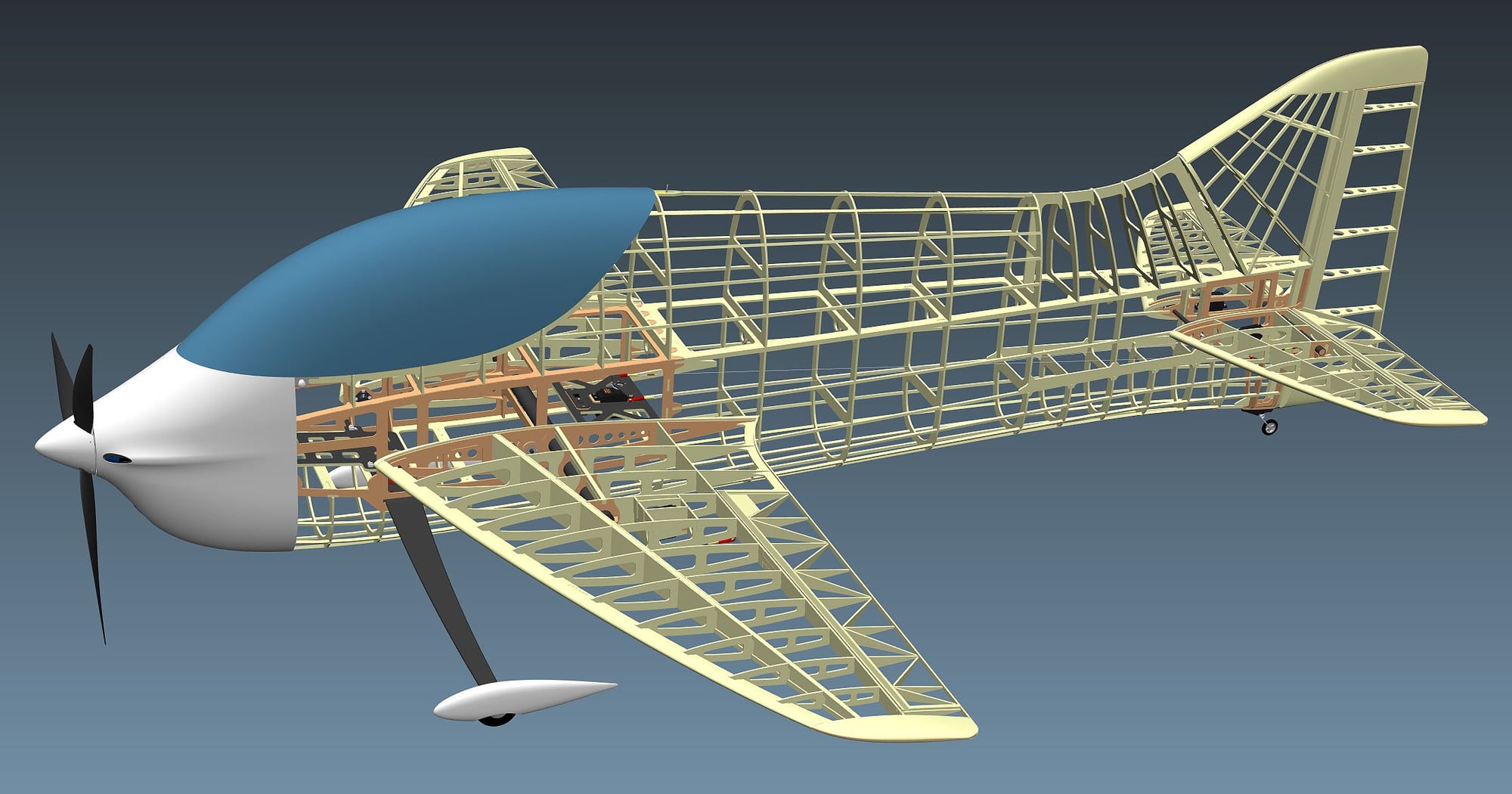
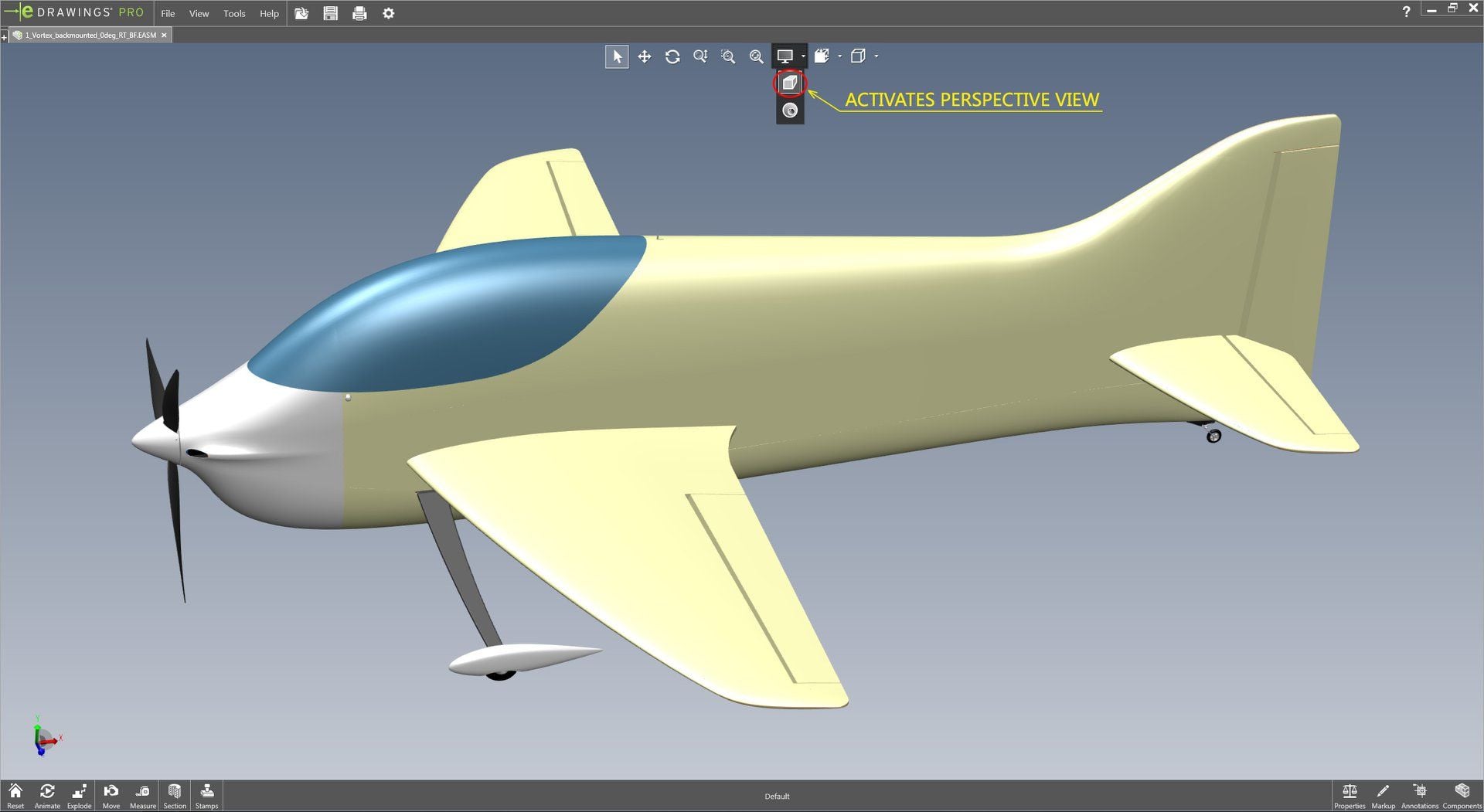
When you open the files in eDrawings, i would recommend enabling the perspective view, especially when looking at the complete plane (see image 1). You can rotate the model by keeping the middle mouse button pressed and moving the mouse around. In combination with the Ctrl and Shift keys, you can also pan and zoom as you wish.
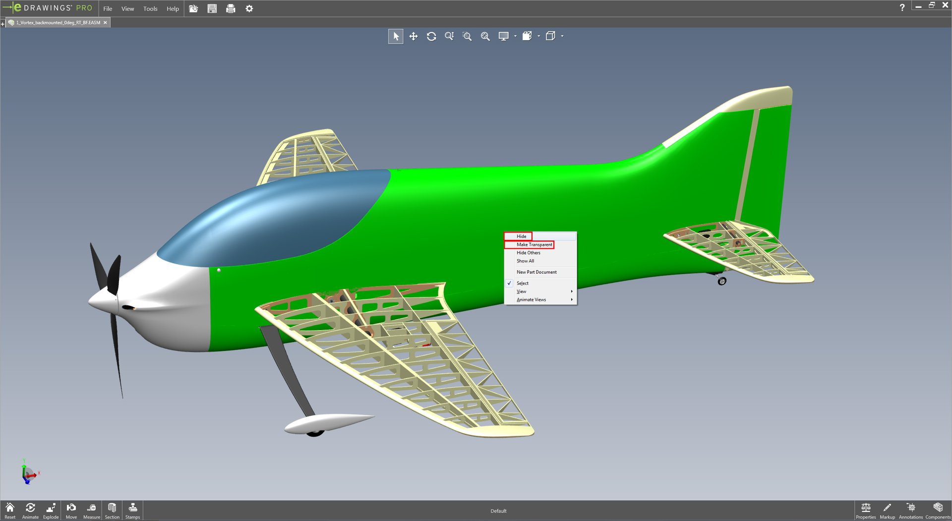
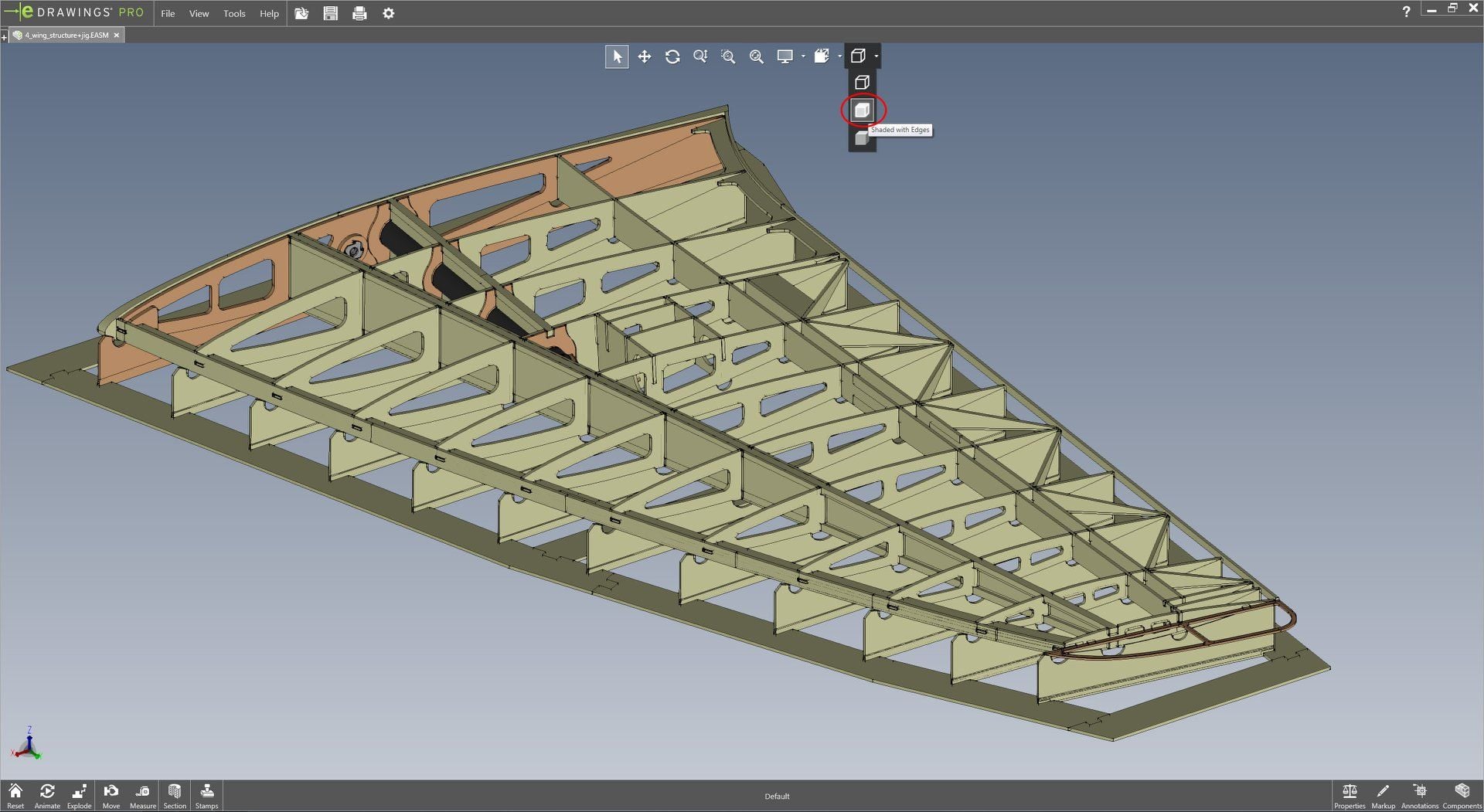
As shown in image 2, if you right-click any part you can hide it or make it transparent (for example you can choose to hide the fuselage or wing balsa covering to reveal the internal structure). It's also possible to display the edges and outlines (image 3) to see some separation lines between parts that would be invisible otherwise.
The floor shadow can be disabled by going to Tools > Options> uncheck "Display shadows" box. eDrawings is very easy to understand so you will learn very quickly to measure distances or make section views.
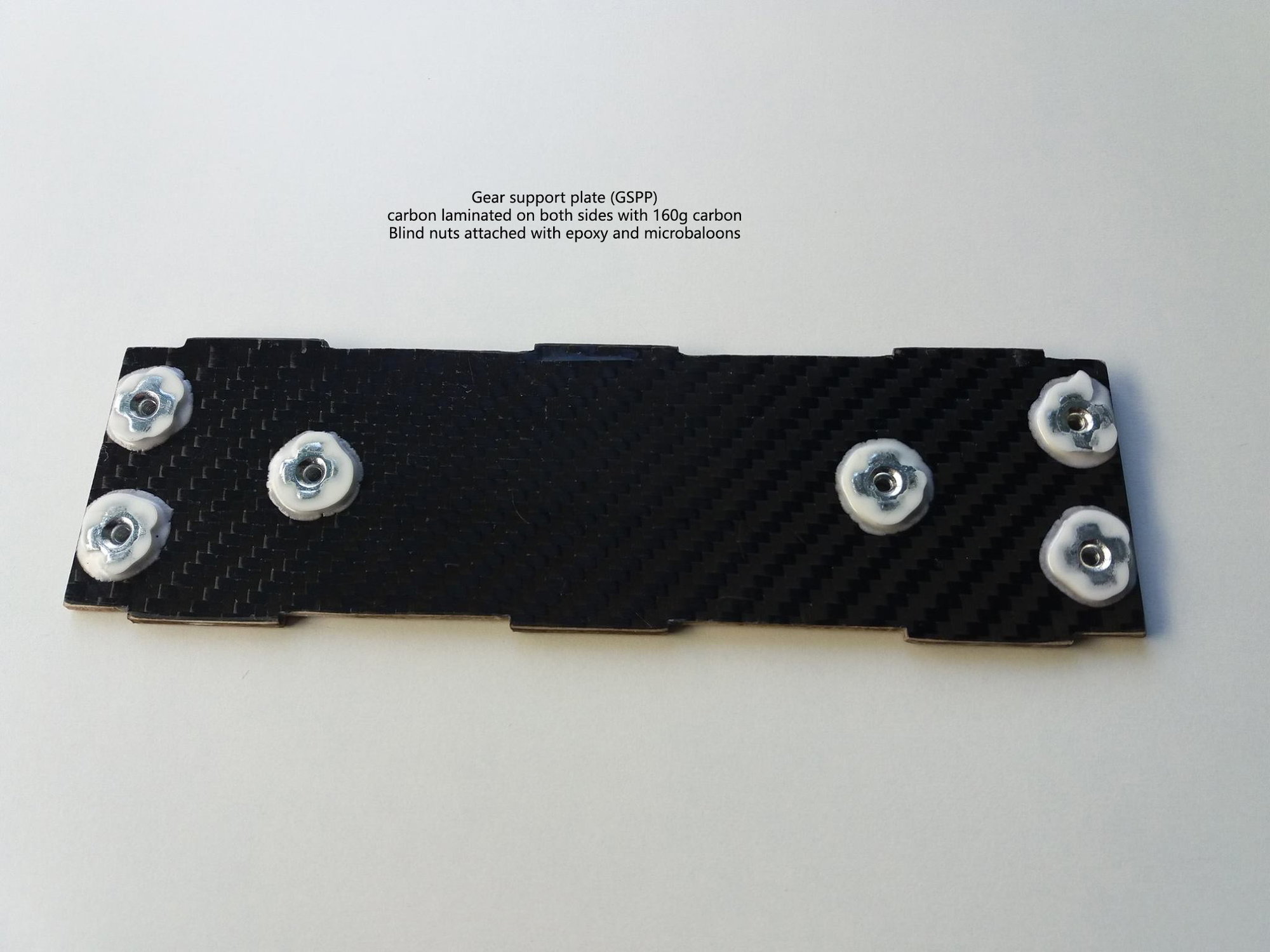
In general all yellow parts are made of balsa and the light brown parts are either liteply or regular plywood. Some parts have black faces on top and bottom, which means they are carbon laminated or made of carbon-balsa sandwich. This will be described in detail later in the assembly manual.
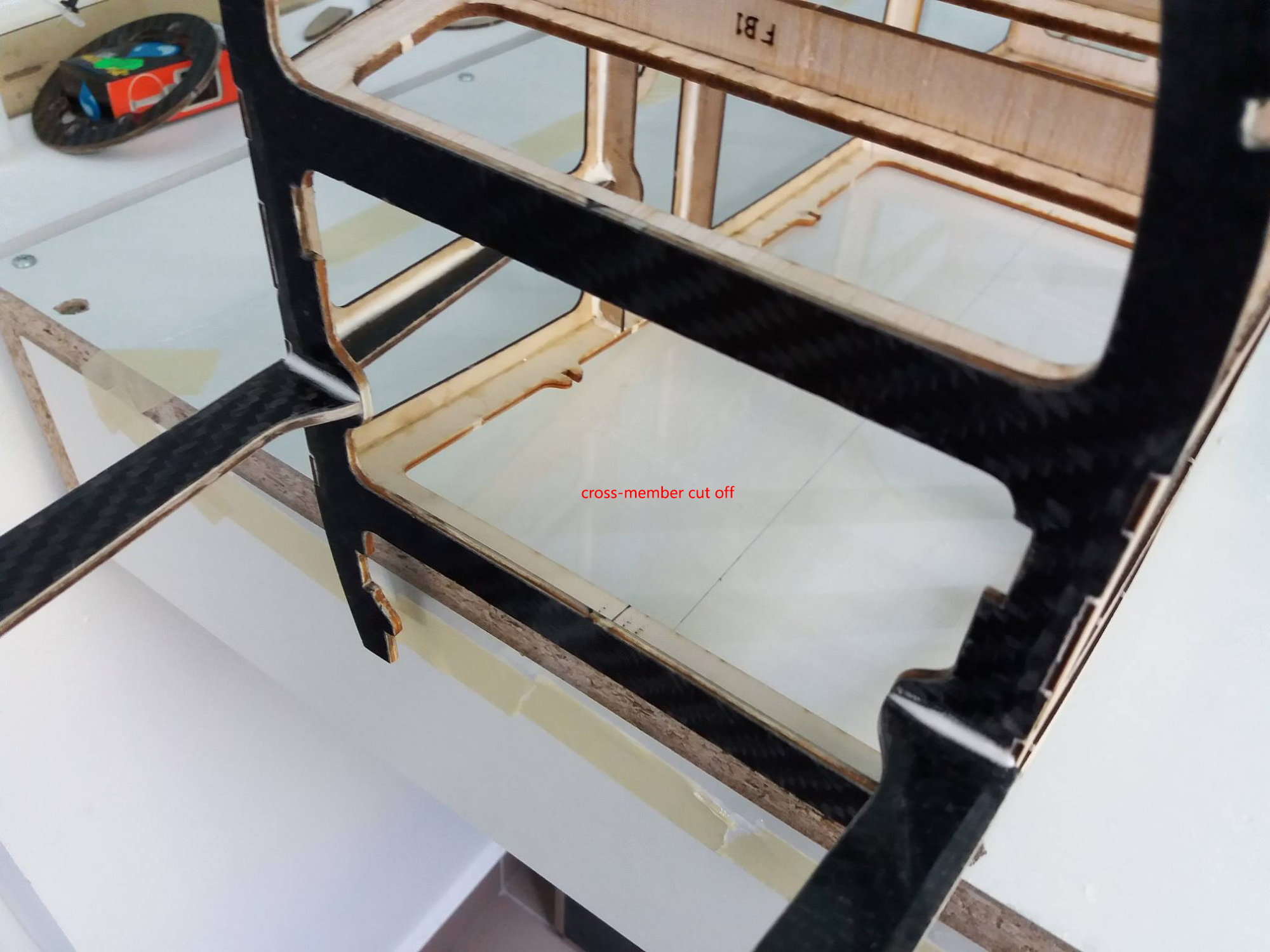
If you look at the fuselage assembly (files named "fuselage frontmounted/ backmounted"), you will see many cross-members in the canopy area, which would normally make the access to the batteries or radio equipment very difficult. But most of these only have a technological role and their central part will be cut off after the fuselage balsa covering is added. The 3D model of the complete plane (files named "Vortex frontmounted/ backmounted") should give you an idea which cross-members will be cut and which will stay in place.
Download links
Vortex BF (Blended fin) 3D files: https://drive.google.com/open?id=1XM...stRiztSiZlvxu6
Vortex SF (Simplified fin) 3D files: https://drive.google.com/open?id=1Rj...b5IpAlNqg-kx9T
The purpose of these files is to have a digital mock-up of the complete model and a general view of the sub-assemblies before building them. It should help to visually identify the parts and their position on the model, although it's not possible to identify them by the codes engraved on the parts.
To open these files you will need to install a free 3D visualization software named eDrawings. It is an official visualization program from Dassault Systemes, so there is no risk in installing it either on your computer or phone/ tablet. You can download it following the link below; all you need is the basic eDrawings viewer, nothing else:
https://www.edrawingsviewer.com/download-edrawings
When you open the files in eDrawings, i would recommend enabling the perspective view, especially when looking at the complete plane (see image 1). You can rotate the model by keeping the middle mouse button pressed and moving the mouse around. In combination with the Ctrl and Shift keys, you can also pan and zoom as you wish.
As shown in image 2, if you right-click any part you can hide it or make it transparent (for example you can choose to hide the fuselage or wing balsa covering to reveal the internal structure). It's also possible to display the edges and outlines (image 3) to see some separation lines between parts that would be invisible otherwise.
The floor shadow can be disabled by going to Tools > Options> uncheck "Display shadows" box. eDrawings is very easy to understand so you will learn very quickly to measure distances or make section views.
In general all yellow parts are made of balsa and the light brown parts are either liteply or regular plywood. Some parts have black faces on top and bottom, which means they are carbon laminated or made of carbon-balsa sandwich. This will be described in detail later in the assembly manual.
If you look at the fuselage assembly (files named "fuselage frontmounted/ backmounted"), you will see many cross-members in the canopy area, which would normally make the access to the batteries or radio equipment very difficult. But most of these only have a technological role and their central part will be cut off after the fuselage balsa covering is added. The 3D model of the complete plane (files named "Vortex frontmounted/ backmounted") should give you an idea which cross-members will be cut and which will stay in place.
Download links
Vortex BF (Blended fin) 3D files: https://drive.google.com/open?id=1XM...stRiztSiZlvxu6
Vortex SF (Simplified fin) 3D files: https://drive.google.com/open?id=1Rj...b5IpAlNqg-kx9T
 06-18-2019 | 11:28 PM
#6
Thread Starter
06-20-2019 | 03:14 AM
#7
Hi,m
Very nice looking plane. And nice 3D images of the balsa/plywood structure.
Will be interesting when someone has built one and can report some on the flight characteristics.
/Bo
Very nice looking plane. And nice 3D images of the balsa/plywood structure.
Will be interesting when someone has built one and can report some on the flight characteristics.
/Bo
06-21-2019 | 10:53 AM
#8
Thread Starter
Thank you Bem. For me it will be impossible to continue on it this year, but maybe next year i'll be able to finish it.
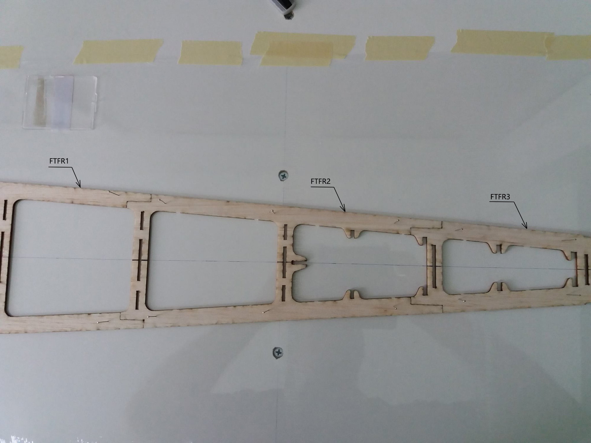
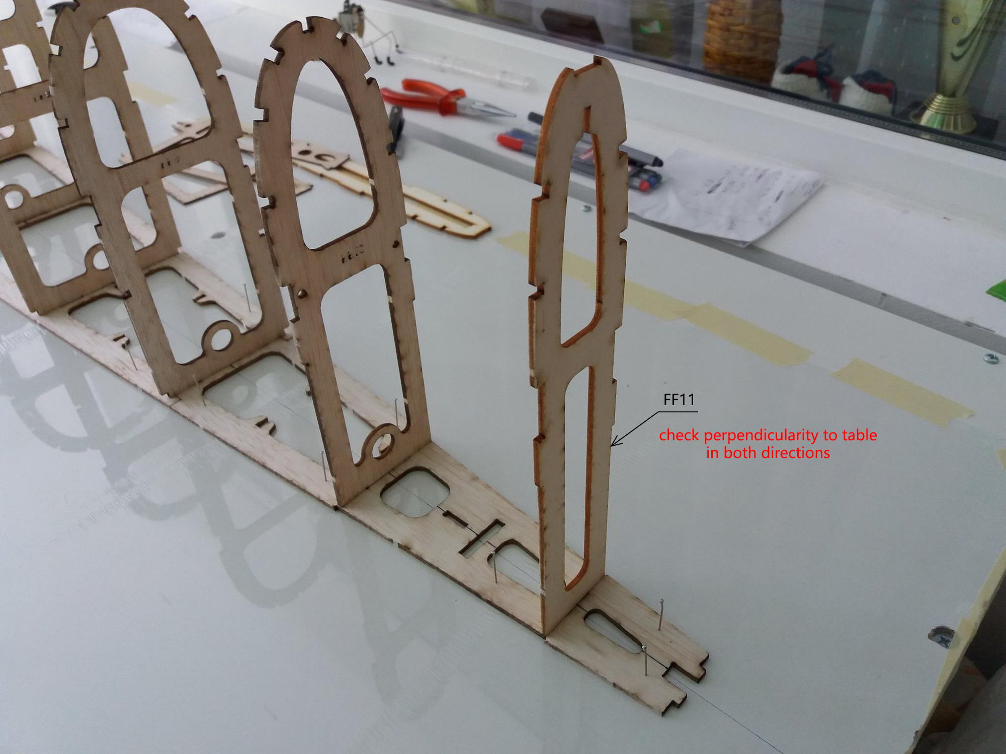
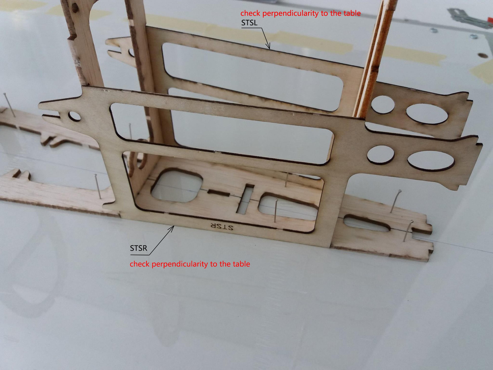
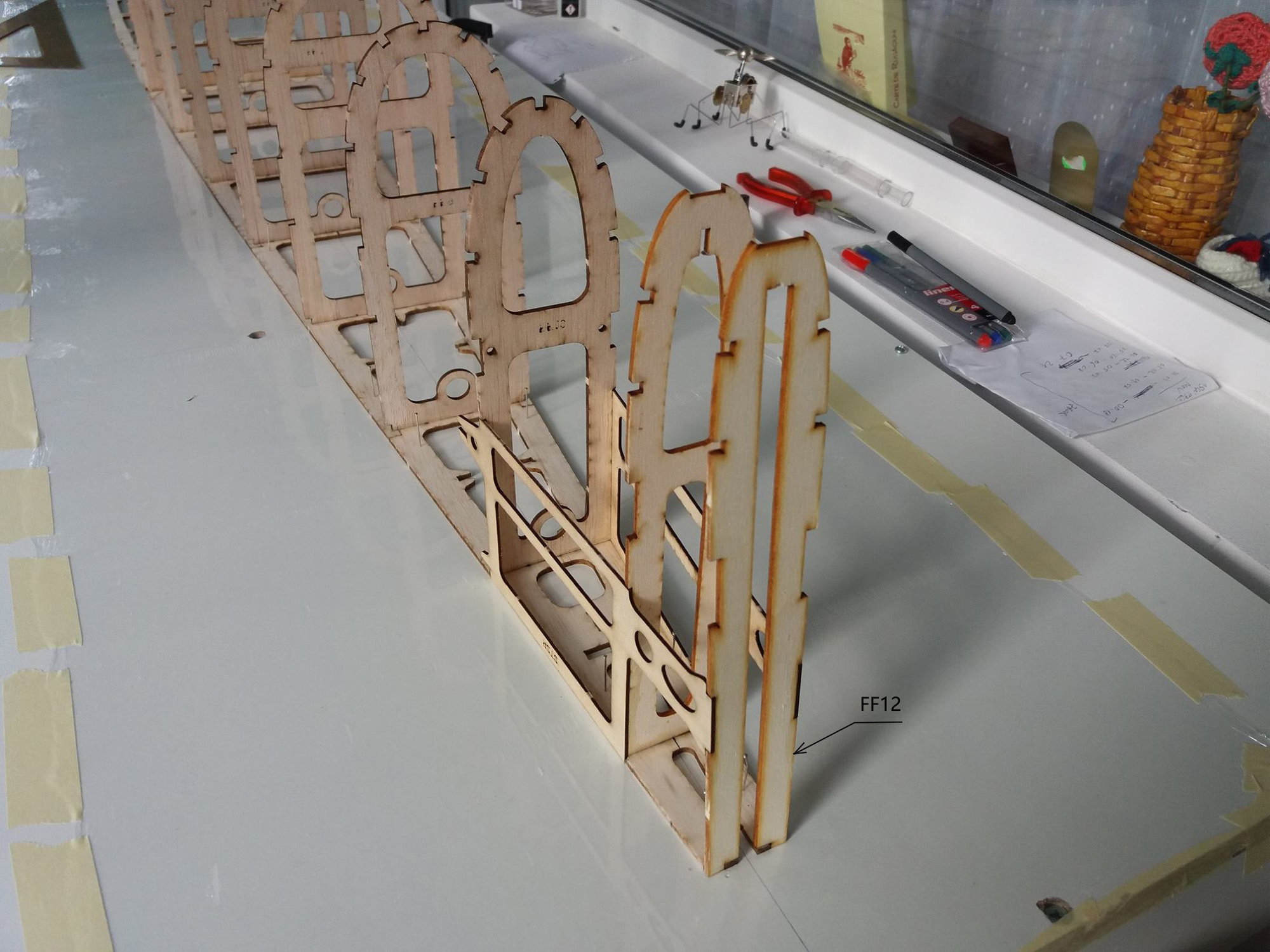
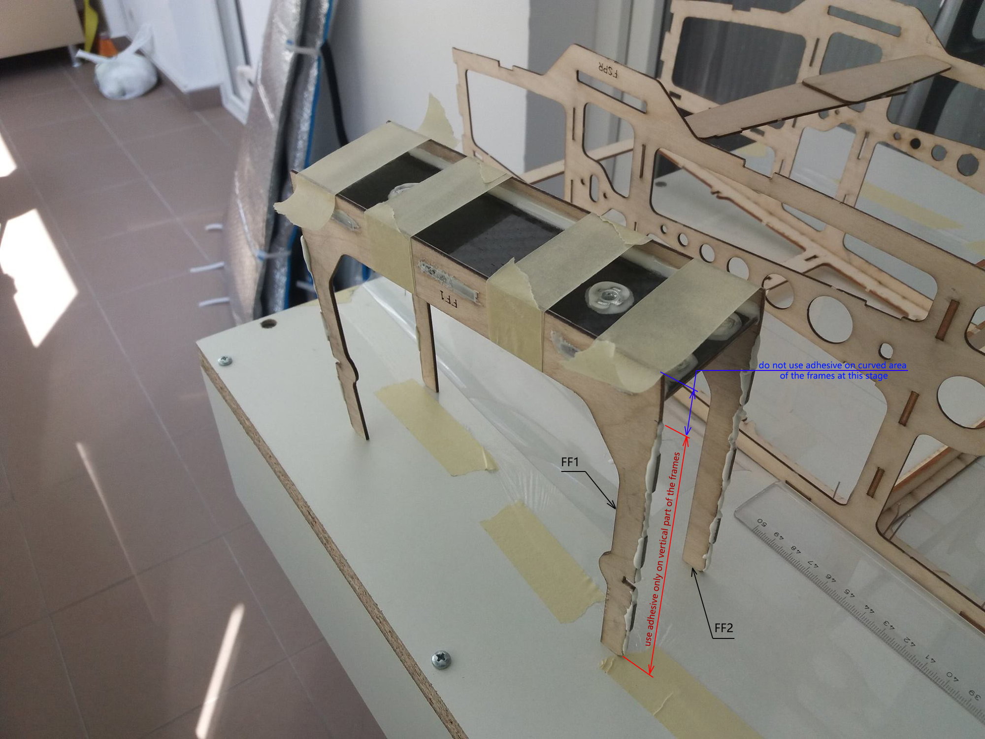
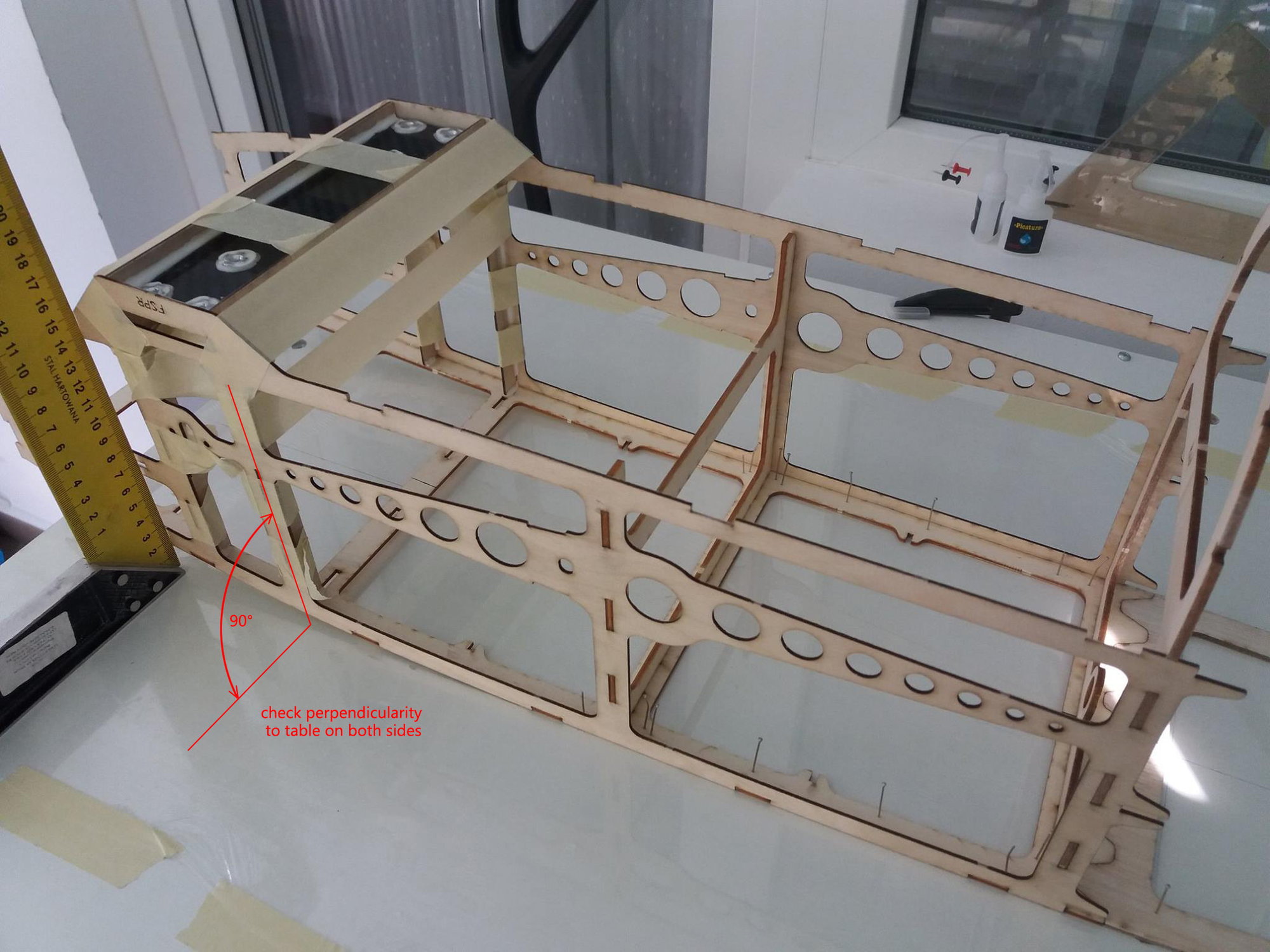
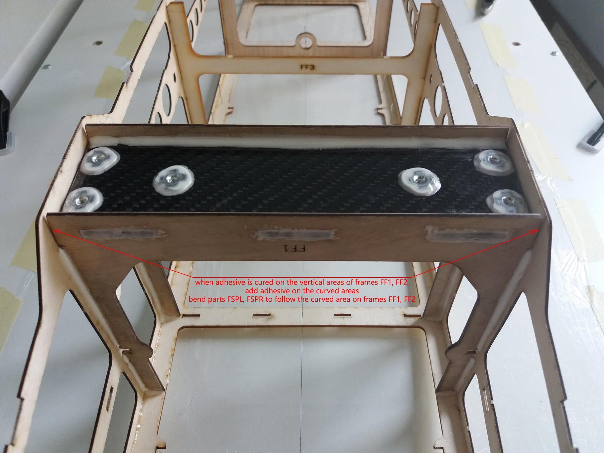
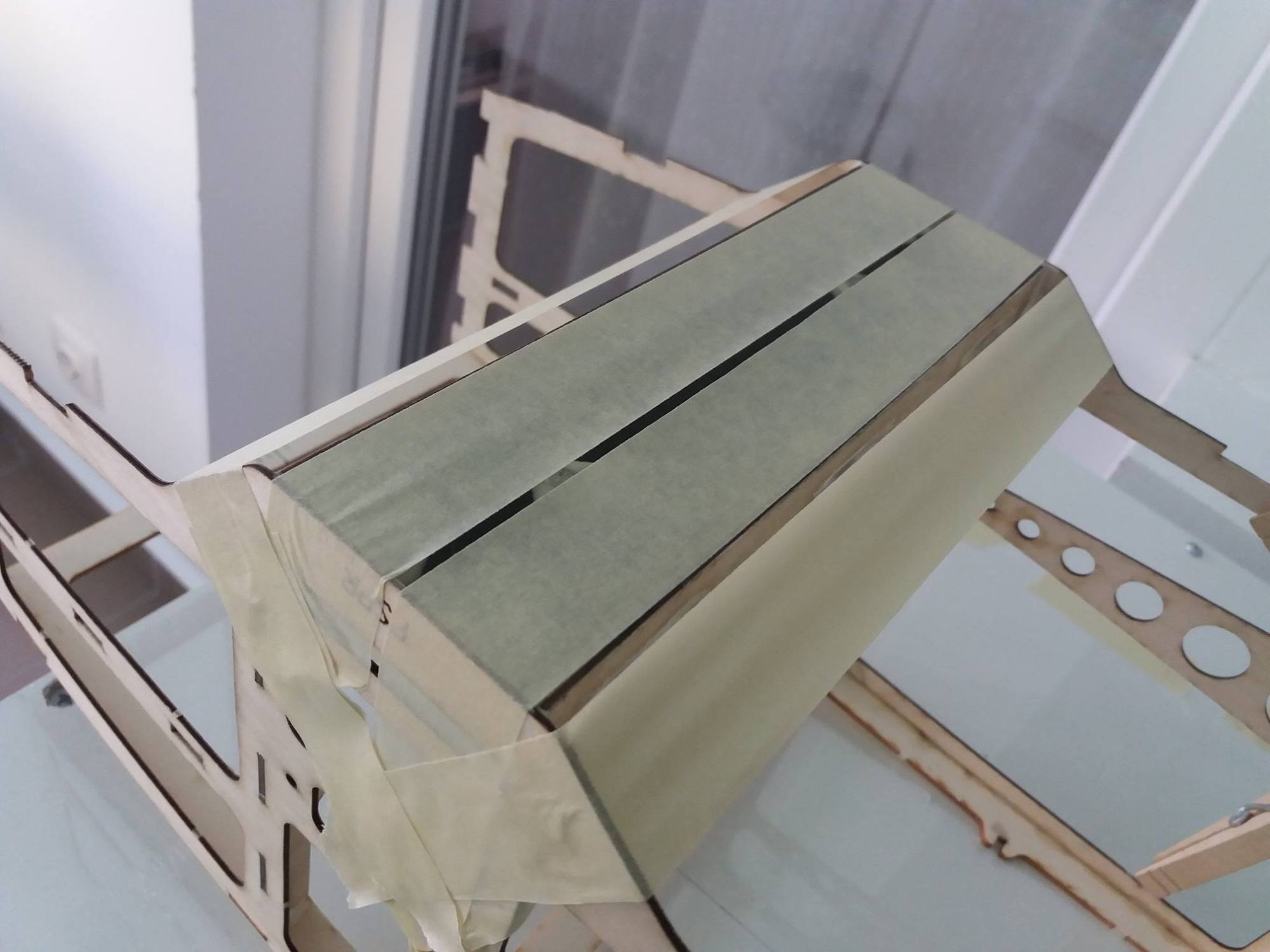
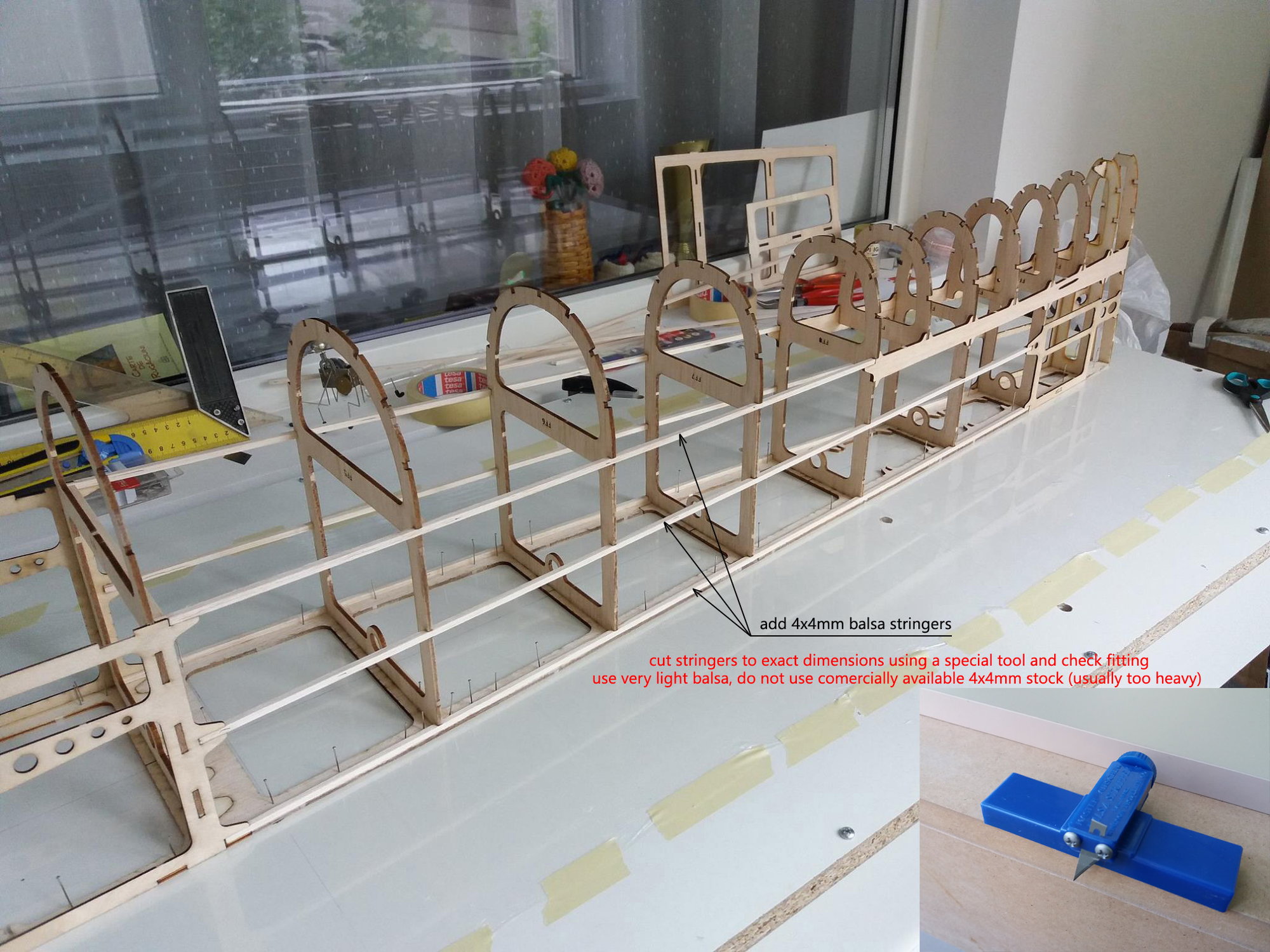
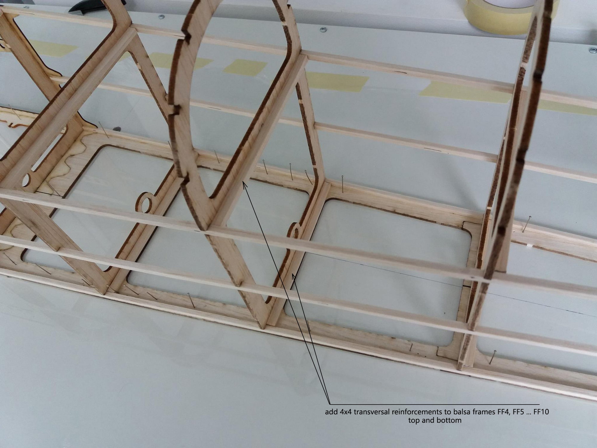
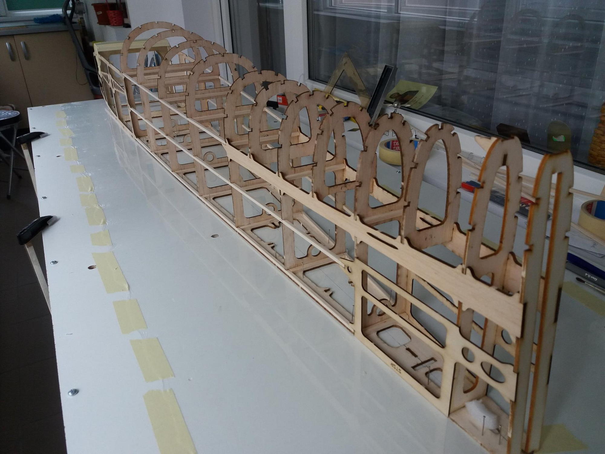
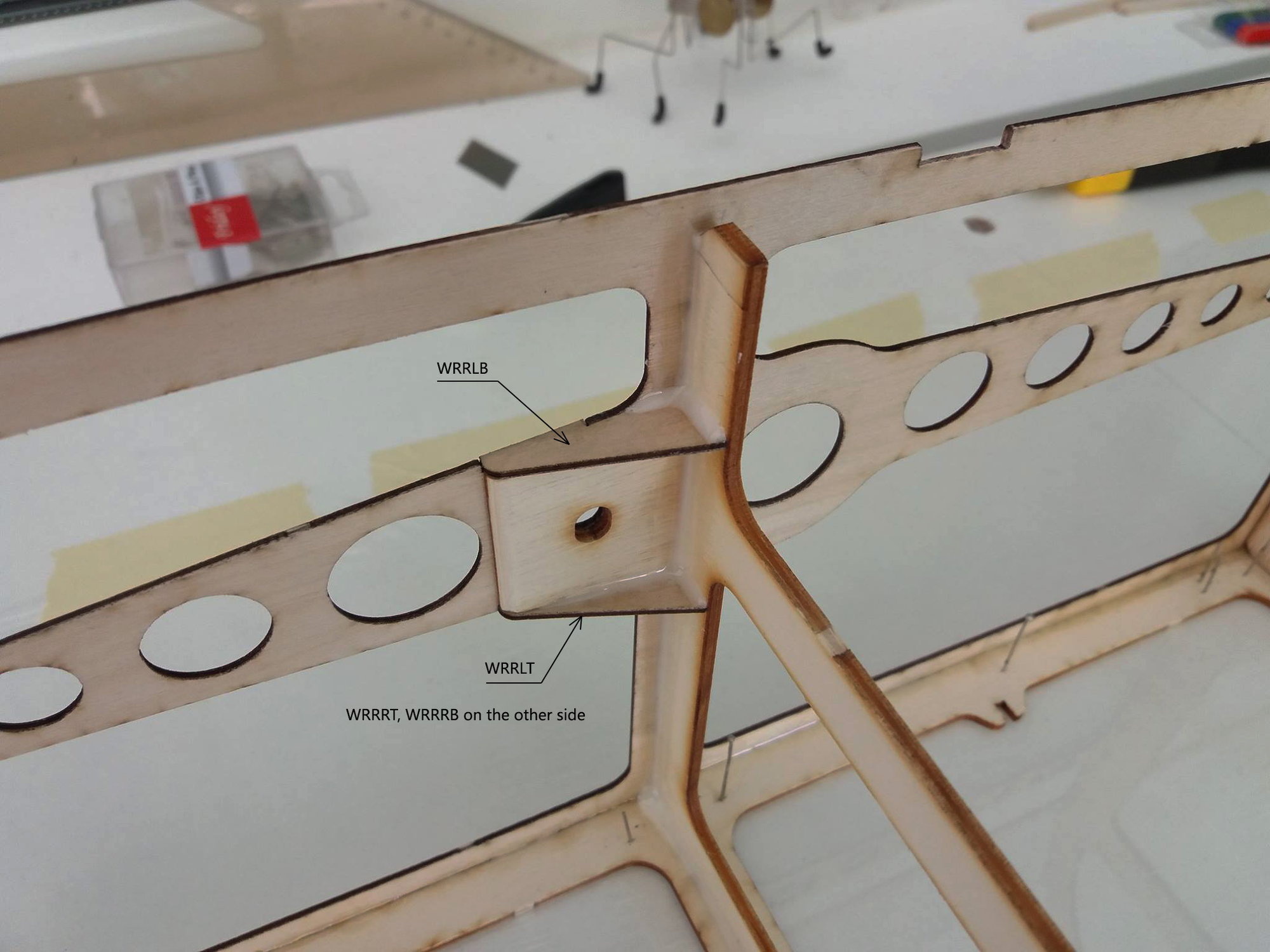
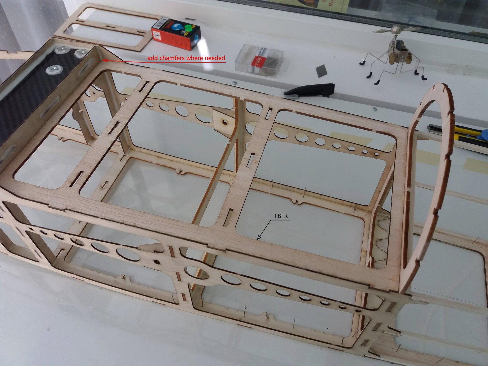
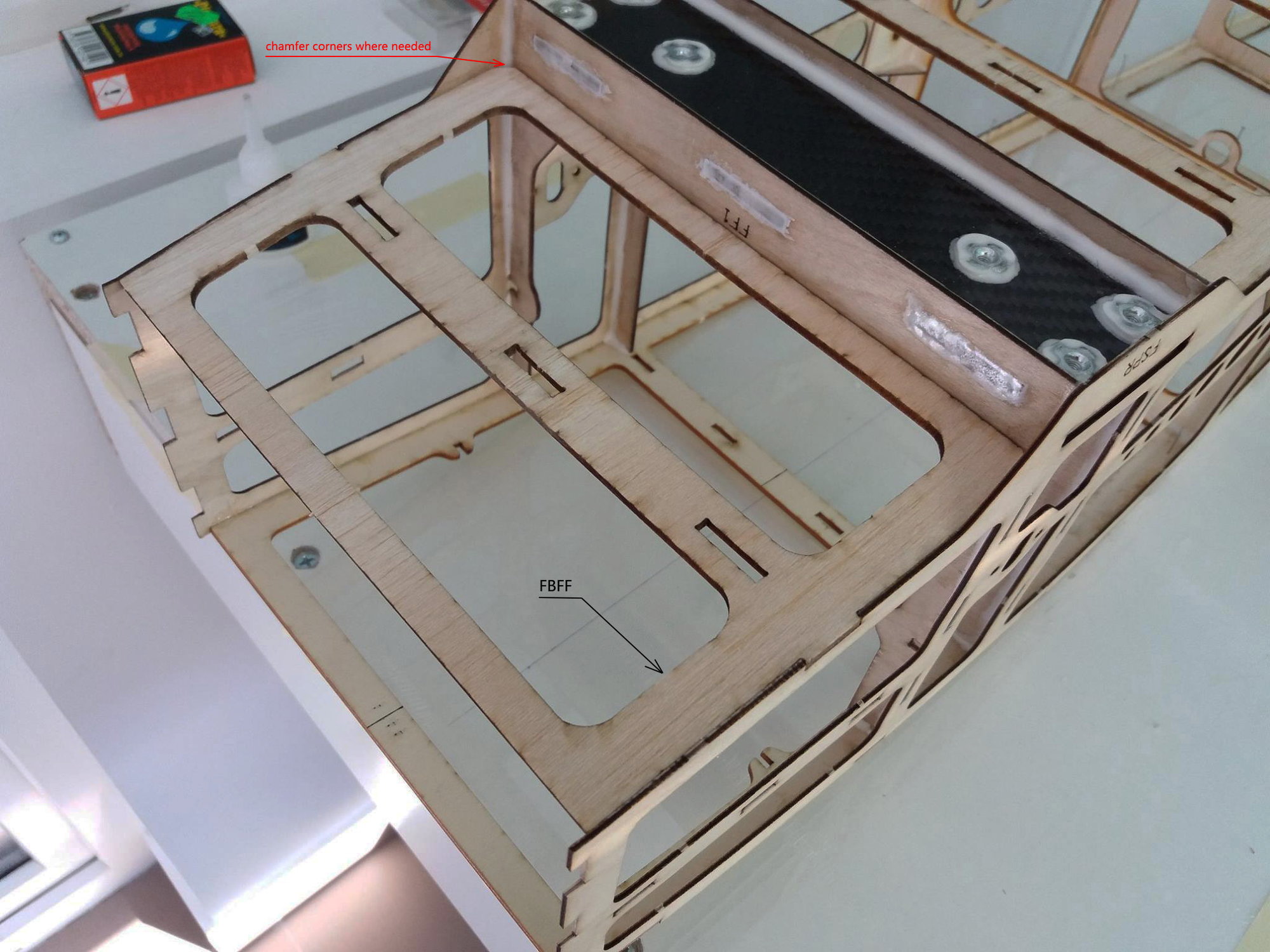
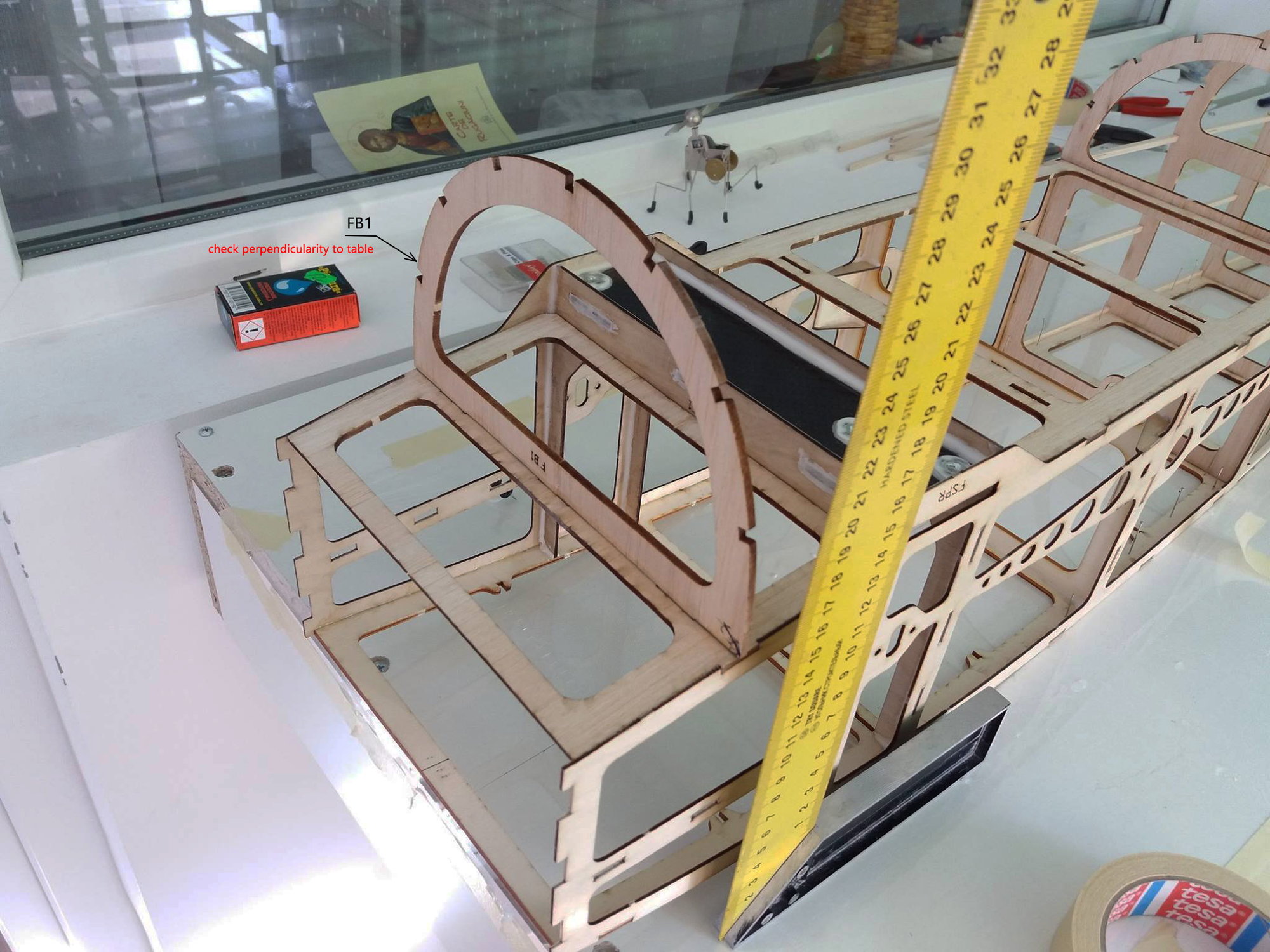
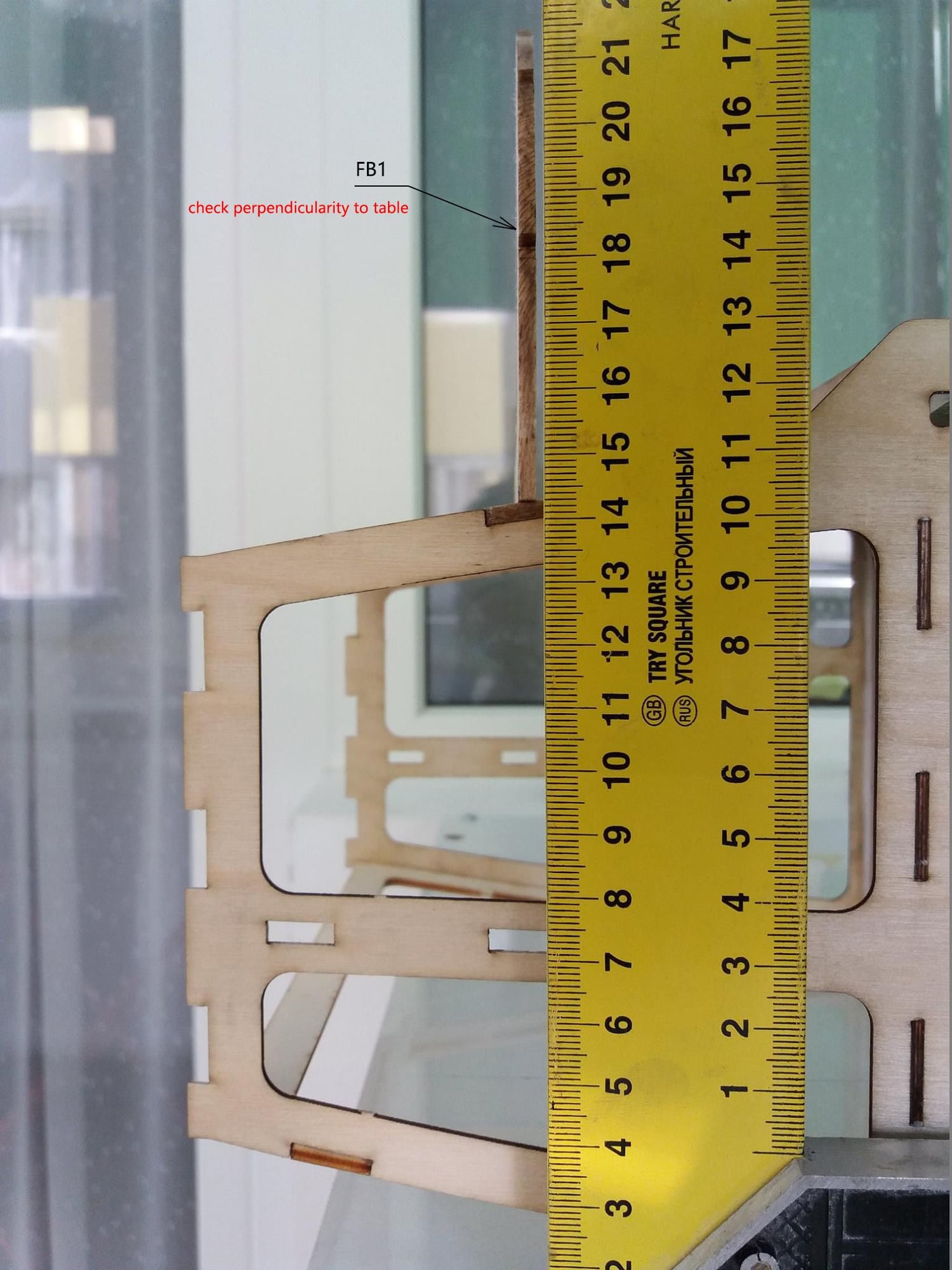
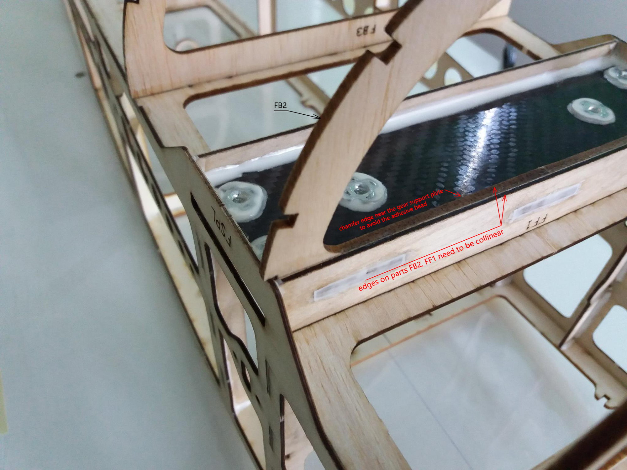
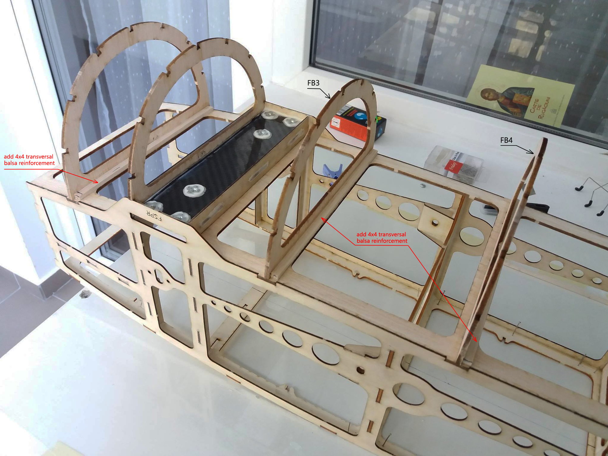
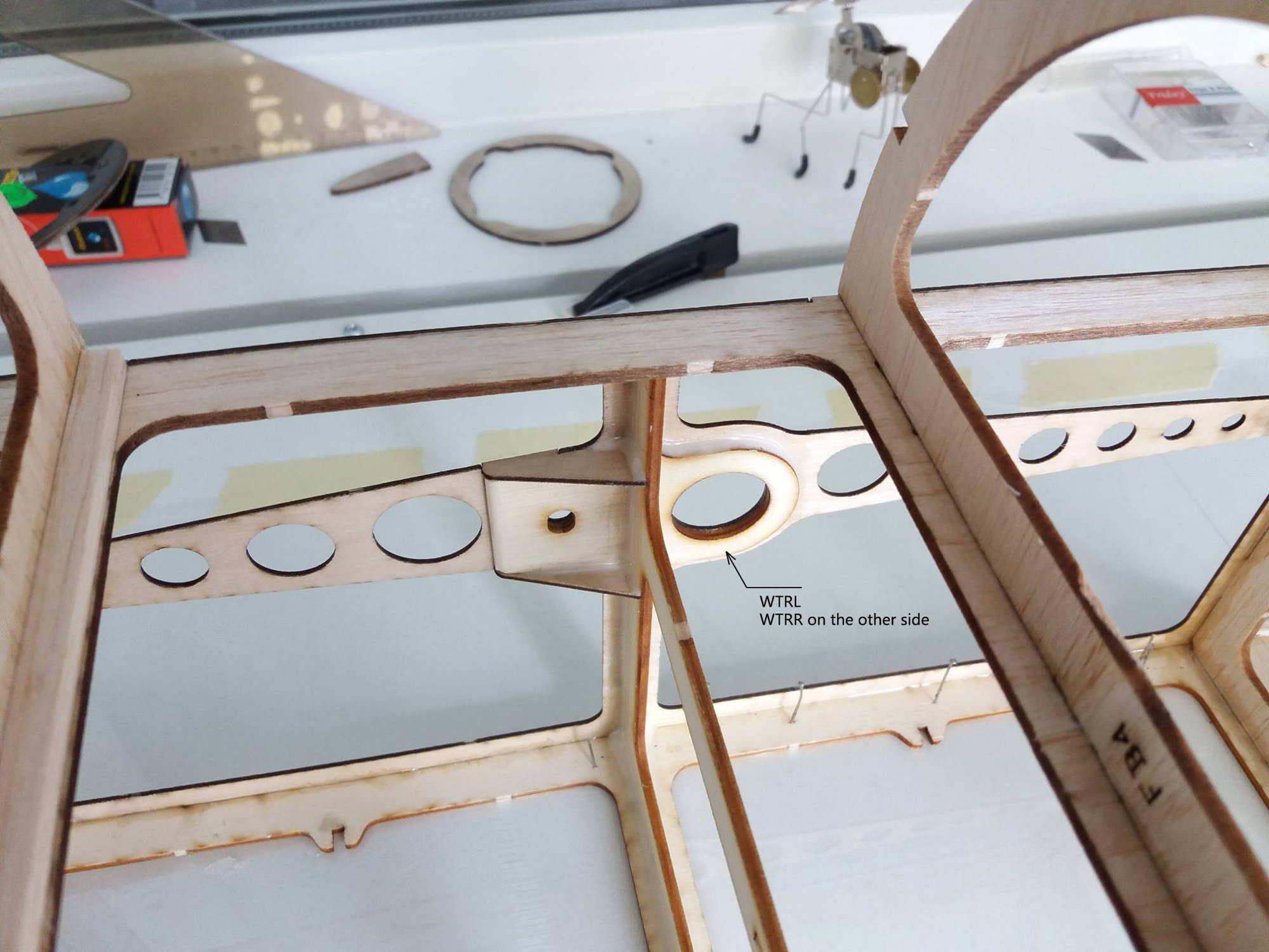
I attached the images for the first part of fuselage assembly. I added the part codes for quick identification and a few notes where i thought it's necessary.
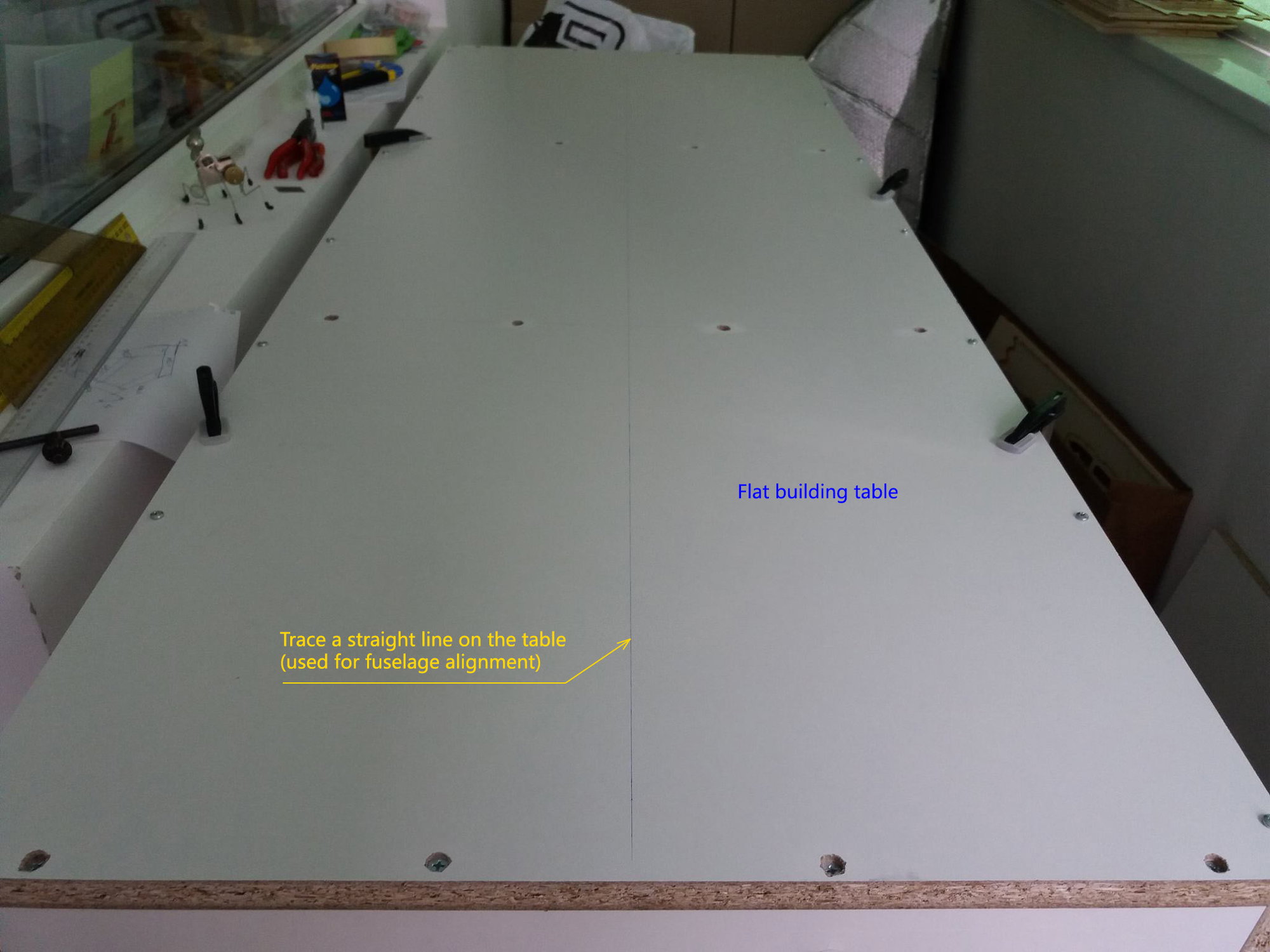
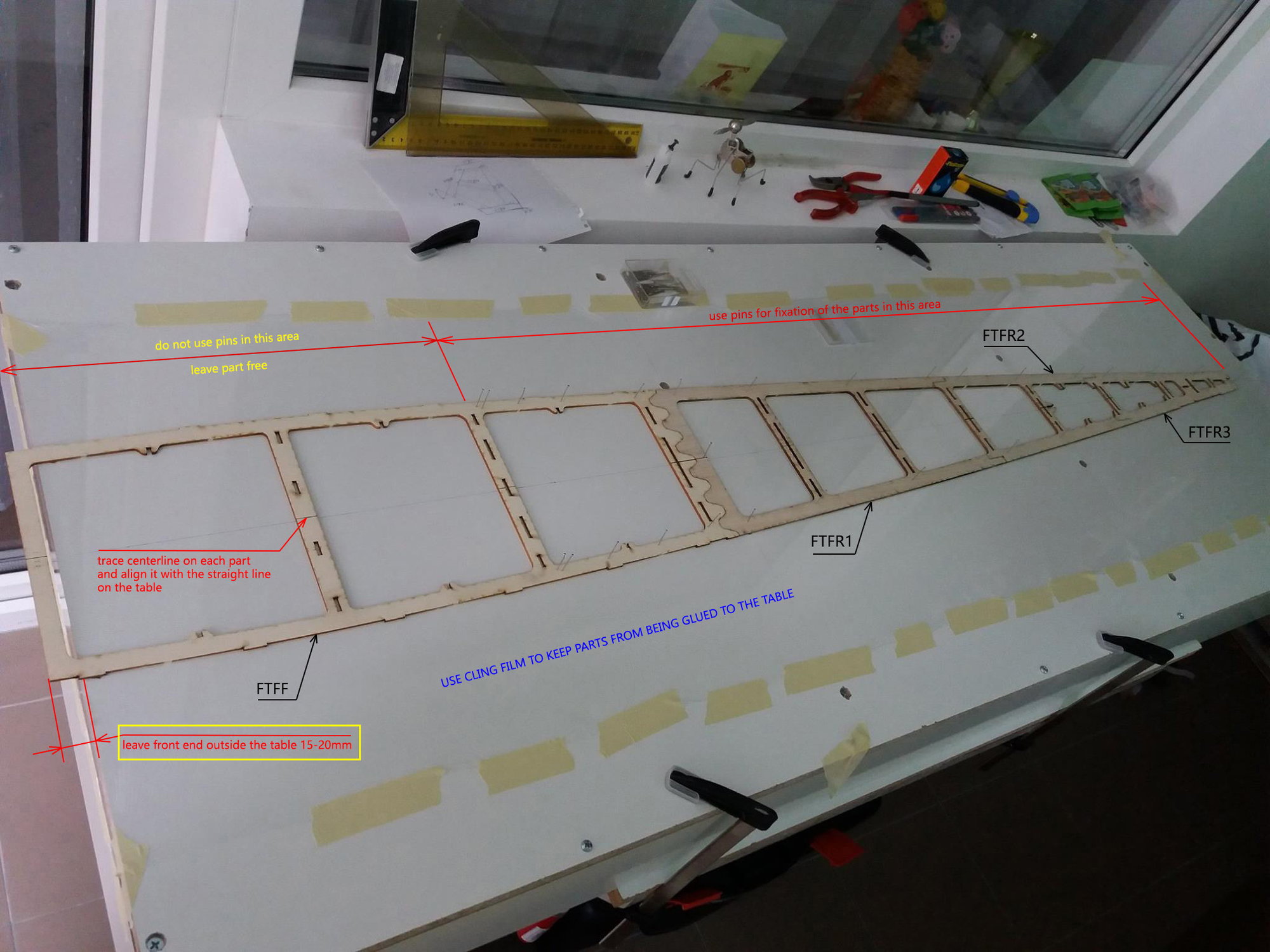
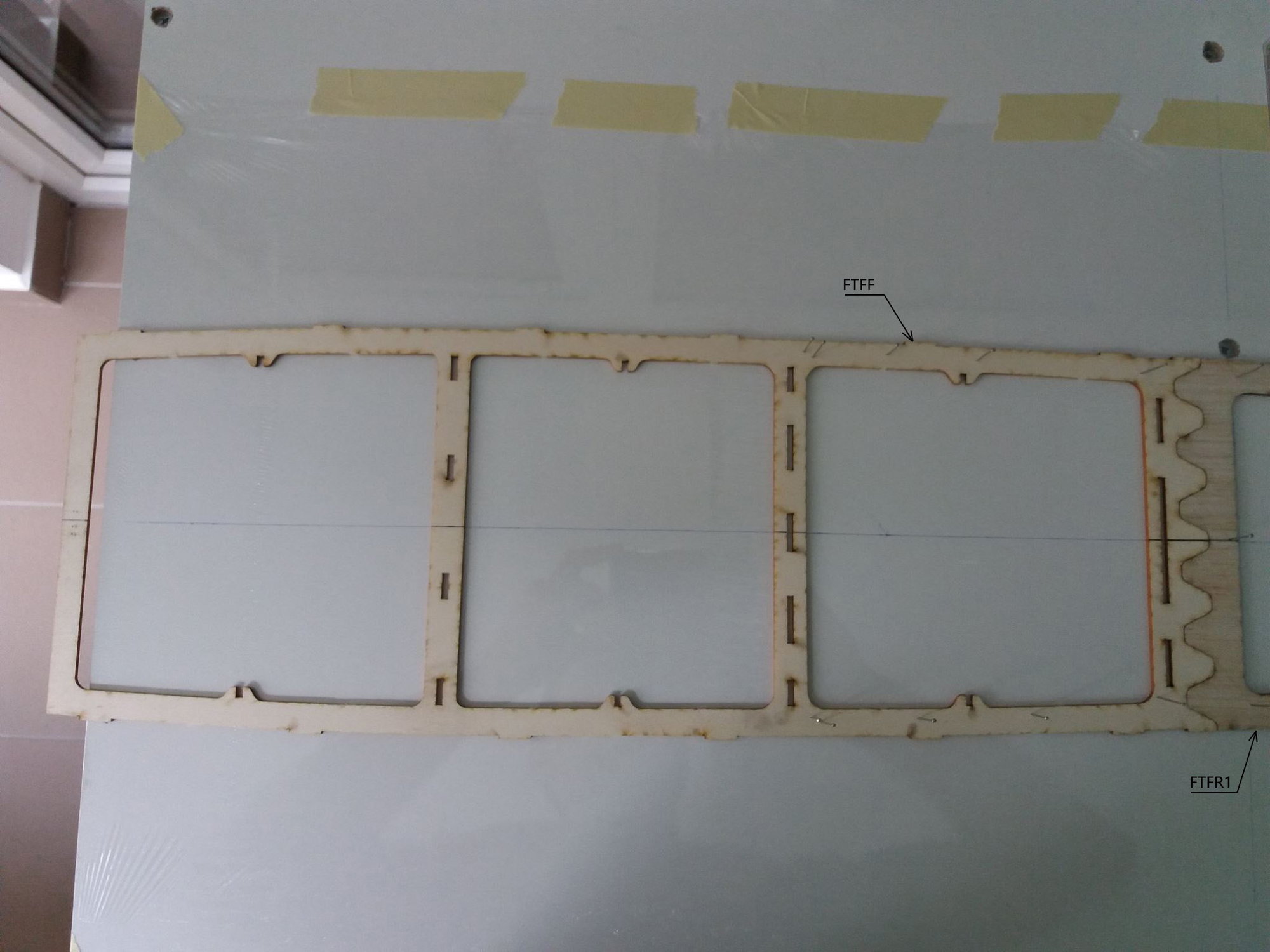
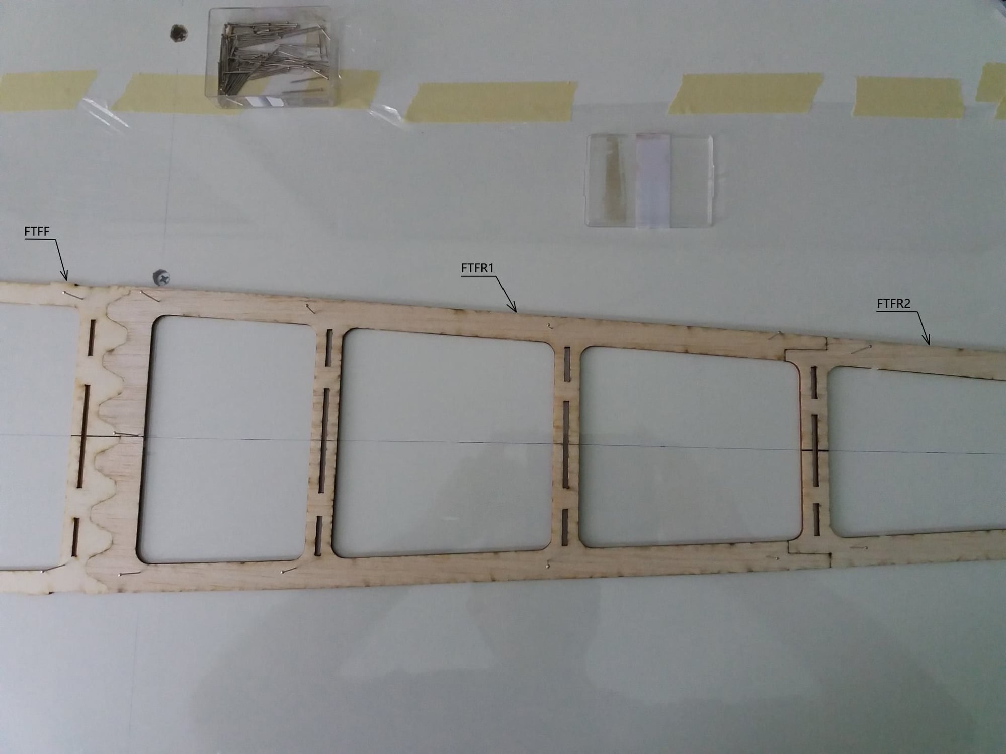

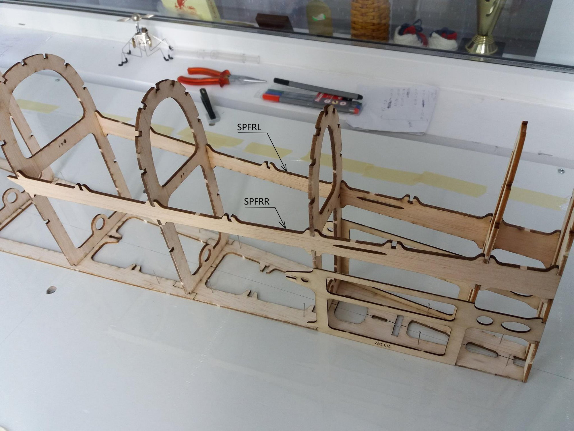
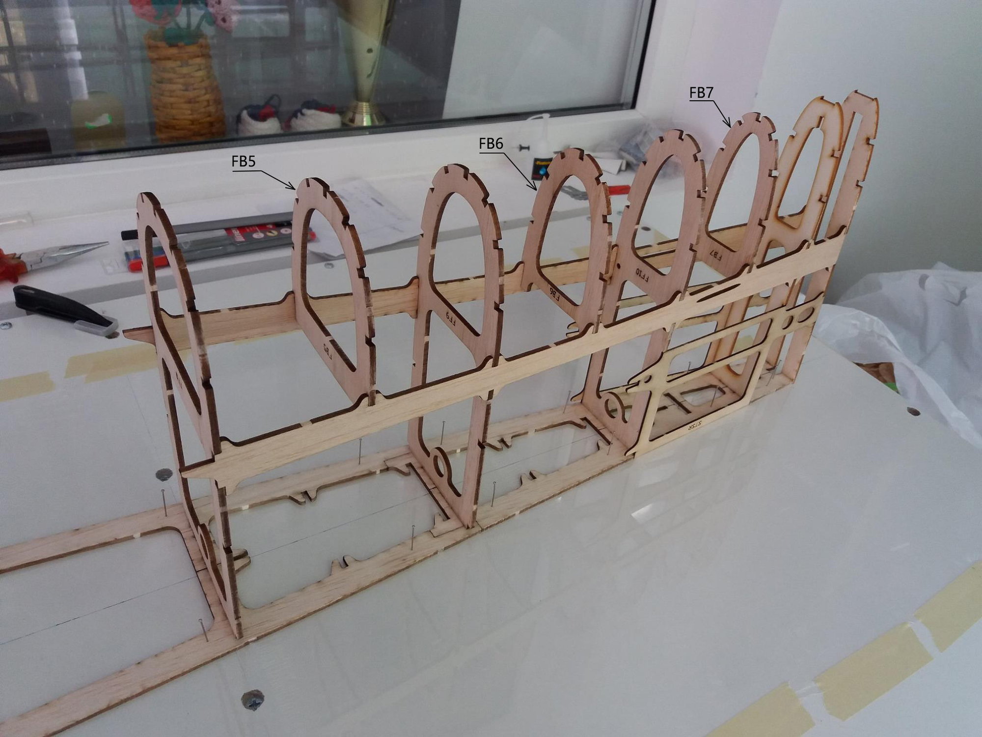
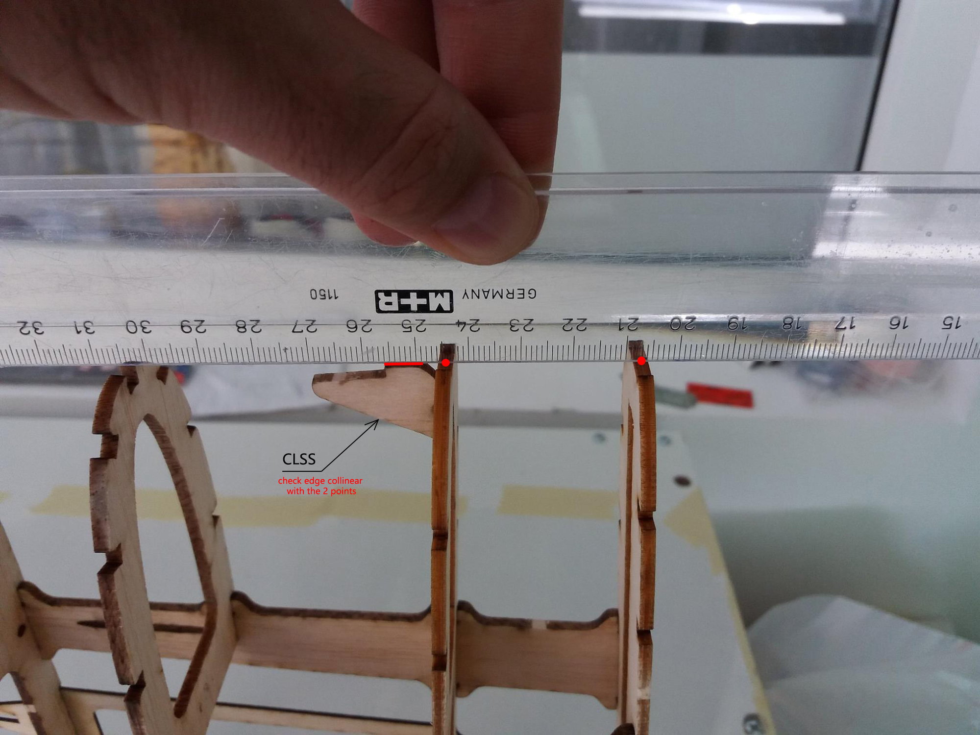
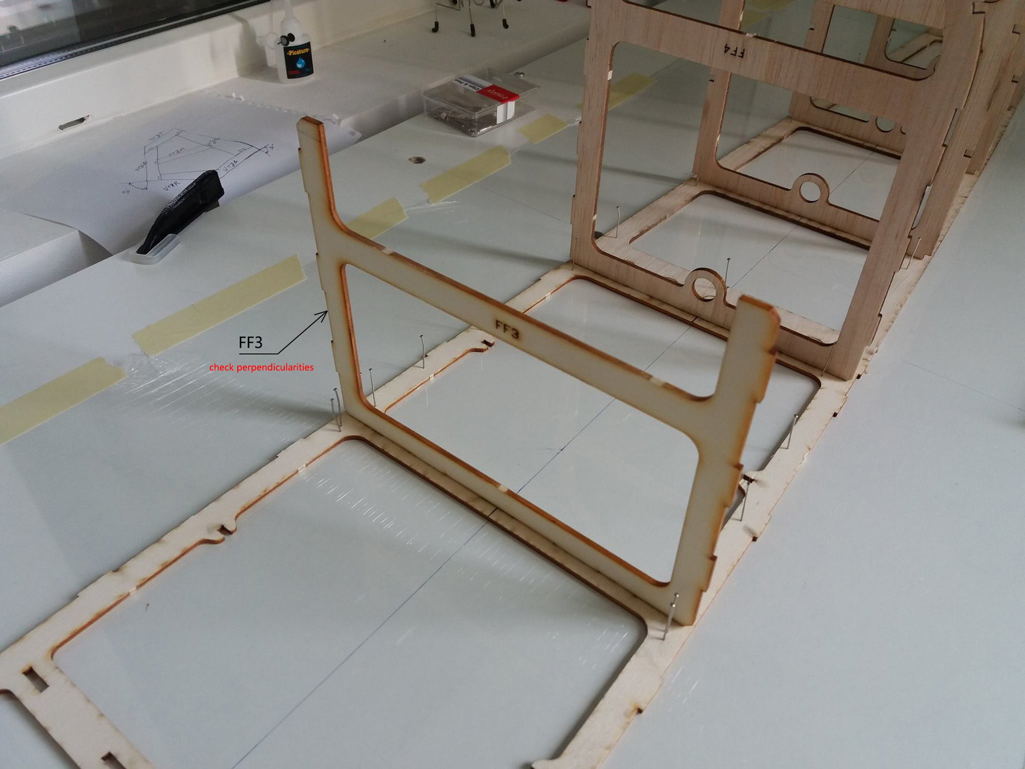
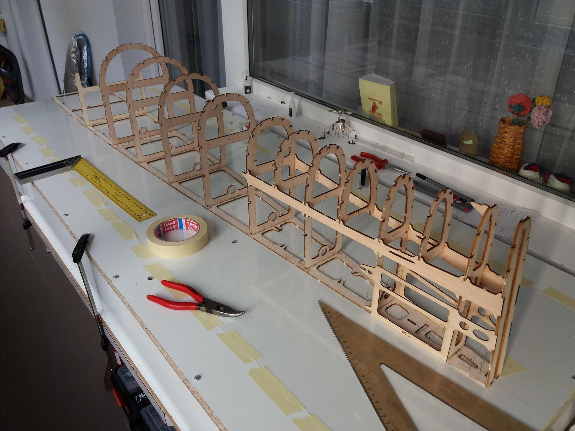
I attached the images for the first part of fuselage assembly. I added the part codes for quick identification and a few notes where i thought it's necessary.


 06-23-2019 | 09:51 AM
#11
Thread Starter
https://www.f3aunlimited.com/gator-7...ve-gc1001-2411
https://www.f3aunlimited.com/gator-c...ve-11mm-gs1009
The fuselage flat sides are covered with 3mm balsa, and the curved areas at the top and bottom with 2mm balsa.
06-23-2019 | 12:18 PM
#12

My Feedback: (121)
Hi Alex,
As usual, fantastic engineering and craftsmanship. I'm curious about your design philosophy. F3A seems to have 3 design trends: 1) more wings; biplanes and triplanes; 2) aerodynamic aids like the T-canalizer, SFGs (side force generators), and fuselage strakes; 3) bigger fuselages which increases the side area and fuselage volume. There are, of course, combinations, as well, like Naruke's Advatage monoplane which has a moderately large fuselage and a small T-can with wing SFGs. How did you arrive at your Vortex design? I like the simplicity of one wing and no aerodynamic gadgets.
Thanks,
Will
06-24-2019 | 01:03 AM
#13
Thread Starter
Hi Alex,
As usual, fantastic engineering and craftsmanship. I'm curious about your design philosophy. F3A seems to have 3 design trends: 1) more wings; biplanes and triplanes; 2) aerodynamic aids like the T-canalizer, SFGs (side force generators), and fuselage strakes; 3) bigger fuselages which increases the side area and fuselage volume. There are, of course, combinations, as well, like Naruke's Advatage monoplane which has a moderately large fuselage and a small T-can with wing SFGs. How did you arrive at your Vortex design? I like the simplicity of one wing and no aerodynamic gadgets.
Thanks,
Will
As usual, fantastic engineering and craftsmanship. I'm curious about your design philosophy. F3A seems to have 3 design trends: 1) more wings; biplanes and triplanes; 2) aerodynamic aids like the T-canalizer, SFGs (side force generators), and fuselage strakes; 3) bigger fuselages which increases the side area and fuselage volume. There are, of course, combinations, as well, like Naruke's Advatage monoplane which has a moderately large fuselage and a small T-can with wing SFGs. How did you arrive at your Vortex design? I like the simplicity of one wing and no aerodynamic gadgets.
Thanks,
Will

The biplanes are really nice and maybe I�ll design one someday, but at the moment my goal was to develop the monoplane as much as possible before moving on to something completely different.
When designing the Vortex I had a list of things to improve from my previous design Audax (build thread here), so it�s an evolution even if it looks quite different. Audax was designed in 2012, so by the end of 2016 it was a small plane compared to the BJ Craft Invitation or other current designs. For Vortex the fuselage side area was increased massively to improve the rolling and knife edge performance needed for the latest F schedule; also the distribution of the side area was changed and fuselage pressure center moved forward for better handling in crosswinds.
Audax had very narrow wingtips and snap-rolled beautifully but faster than I could move my fingers so I thought I can afford trading some snap roll performance for more predictable spin entries and improved handling in bad weather. That�s why the Vortex wingtips are wider with increased leading edge radius.
The purpose of the canalizer is to improve the knife edge performance. I tested one on my old Radiance design and the knife edge performance was significantly better but at the same time the canalizer induced a strong pull to canopy in horizontal knife edge flight. I tried to adjust the canalizer incidence or move the CG backwards, but nothing really helped so in the end I just gave up on using it. I know other pilots use canalizers with great success but as described a while go in my Airflow Visualization thread, I found other ways to improve knife edge flight:
http://www.rcuniverse.com/forum/rc-p...isation-3.html
I would say the effect of using the 2 fin fences was roughly equal to the canalizer and I received good reports from other pilots that tested them. There was even an article about this in Kfactor magazine (May 2014 issue) and the author�s conclusion was that the fin fences compared favorably to the canalizer:
may14.pdf
So if I�m ever going to need more knife edge performance for Vortex, I will just use the fin fences. The weight is only a few grams and I couldn�t see any disadvantage in using them.
Last edited by Alex Voicu; 06-24-2019 at 01:07 AM.
06-25-2019 | 04:37 AM
#14
My Feedback: (121)
Hi Alex,
Thanks for the great response. I Read all the linked threads again which contain a wealth of information! I also want to thank you for all the time you have spent posting here. Photographing, uploading, and all the text takes a lot of time and effort. Greatly appreciated!
I have a question regarding the Vortex: I am currently looking for a suitable laser cutting professional and realized that all of your dimensions will be metric, but wood here will be 'english'. I plan on requesting all wood sizes be as close as possible, but probably slightly larger. Will this cause any problems with the build? I am not worried about any small weight increase.
Thanks,
Will
06-25-2019 | 06:49 AM
#15
Thread Starter
Hi Alex,
Thanks for the great response. I Read all the linked threads again which contain a wealth of information! I also want to thank you for all the time you have spent posting here. Photographing, uploading, and all the text takes a lot of time and effort. Greatly appreciated!
I have a question regarding the Vortex: I am currently looking for a suitable laser cutting professional and realized that all of your dimensions will be metric, but wood here will be 'english'. I plan on requesting all wood sizes be as close as possible, but probably slightly larger. Will this cause any problems with the build? I am not worried about any small weight increase.
Thanks,
Will
F3A is my passion so it's great to share the information with other pilots, just as many others did over the years.
There are hundreds of interlocking parts in the Vortex kit so imperial wood sizes may cause some problems. You may need to sand some areas to make the parts fit together and this may become annoying when you have a large number of parts. It will mean more work on your part so i am worried you may not enjoy building this model as much as i did.
But if there is no way to source metric size wood, i would suggest choosing the closest approximation even if it's slightly thinner. The differences are only a few tenths of a milimeter, so i'm not worried about the strength:
1.5mm - 1/16
2mm - 5/64
3mm - 1/8
2.5mm - 3/32
6mm - 1/4
8mm - 1/3
10mm - 3/8
I hope this helps.
Alex
The following users liked this post:
Tolvai (07-23-2020)
06-25-2019 | 12:58 PM
#16
Thread Starter
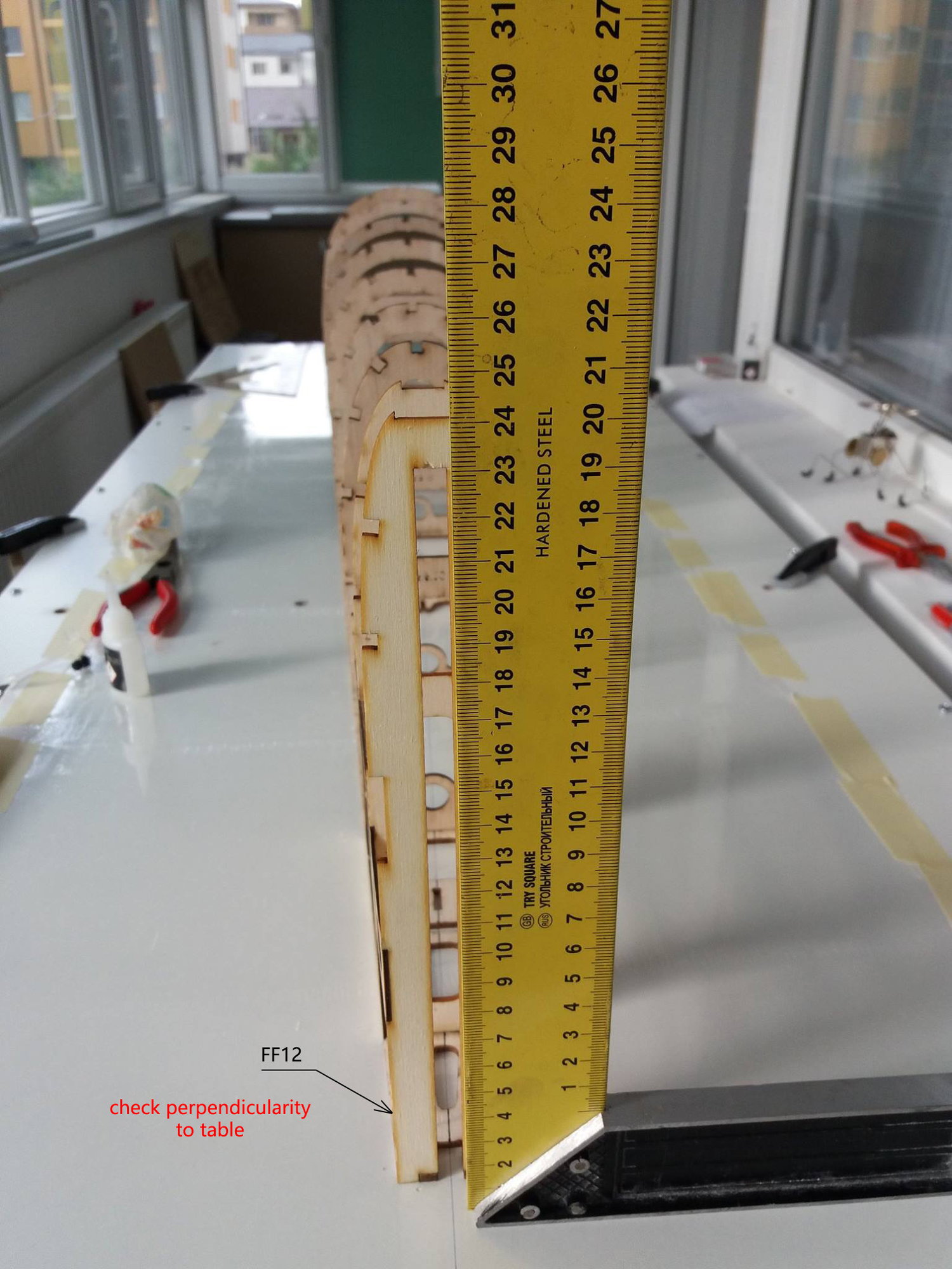
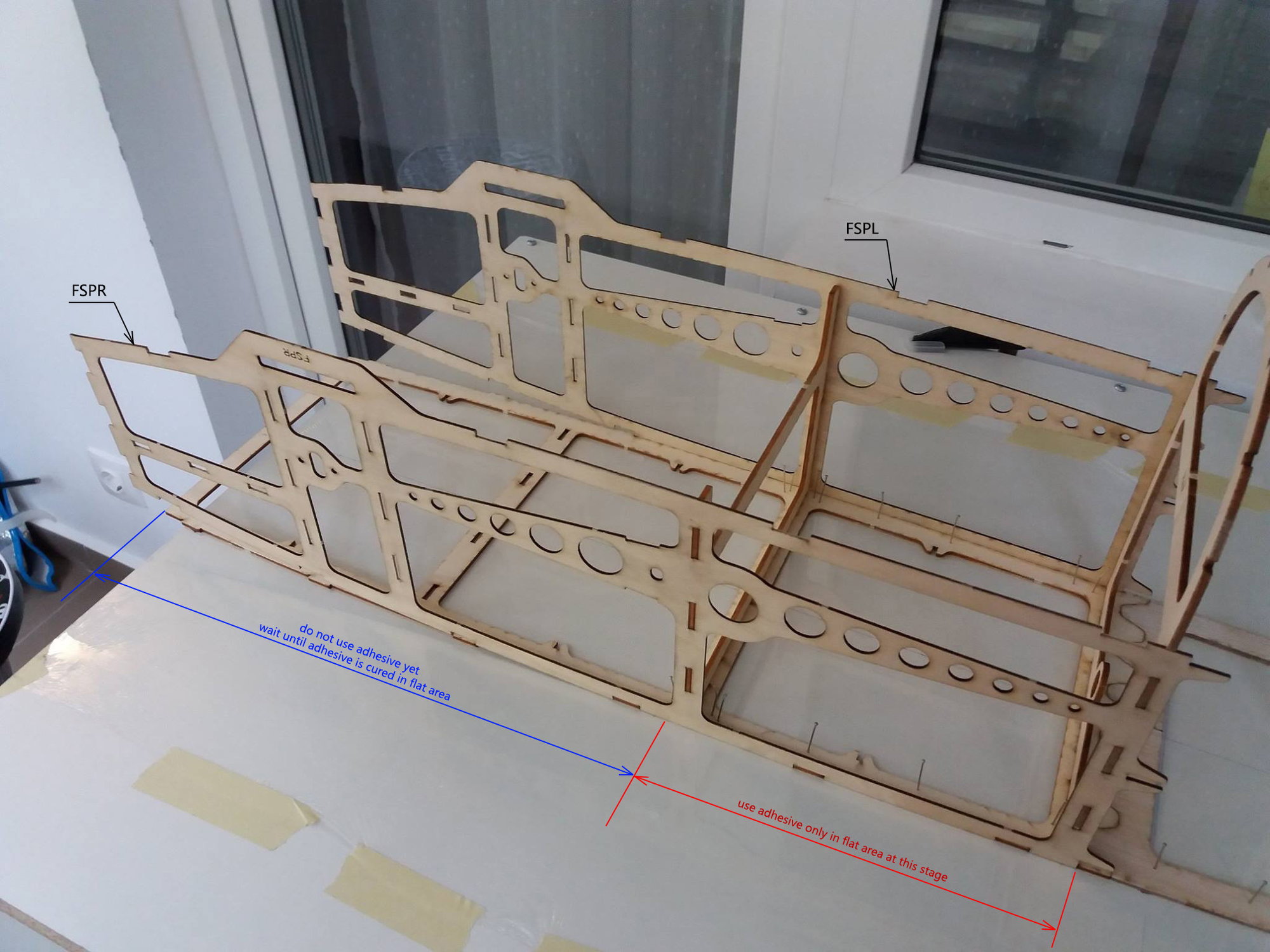
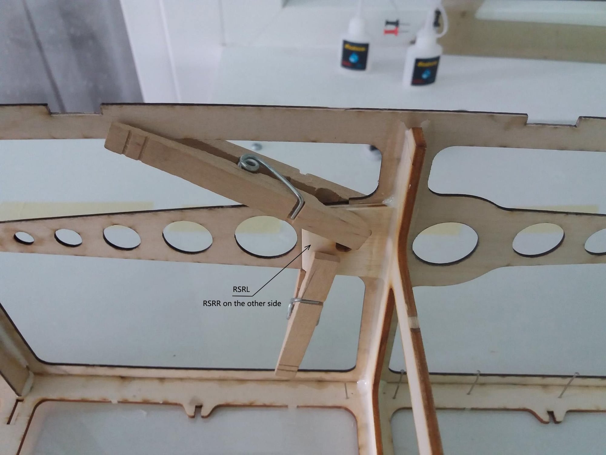
Fuselage assembly part 3
One of the fuselage frames (FB2-B) was added after building my prototype fuselage, so it's missing from my build photos but i added a CAD image to show it.
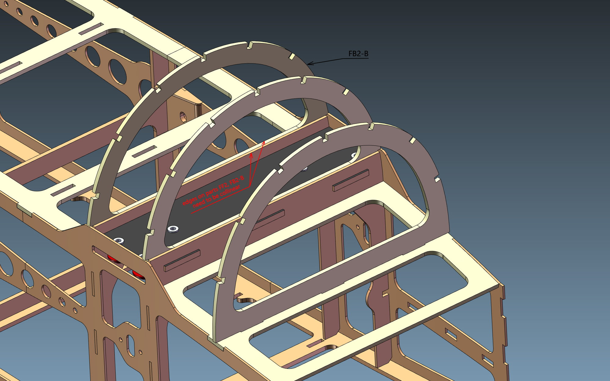
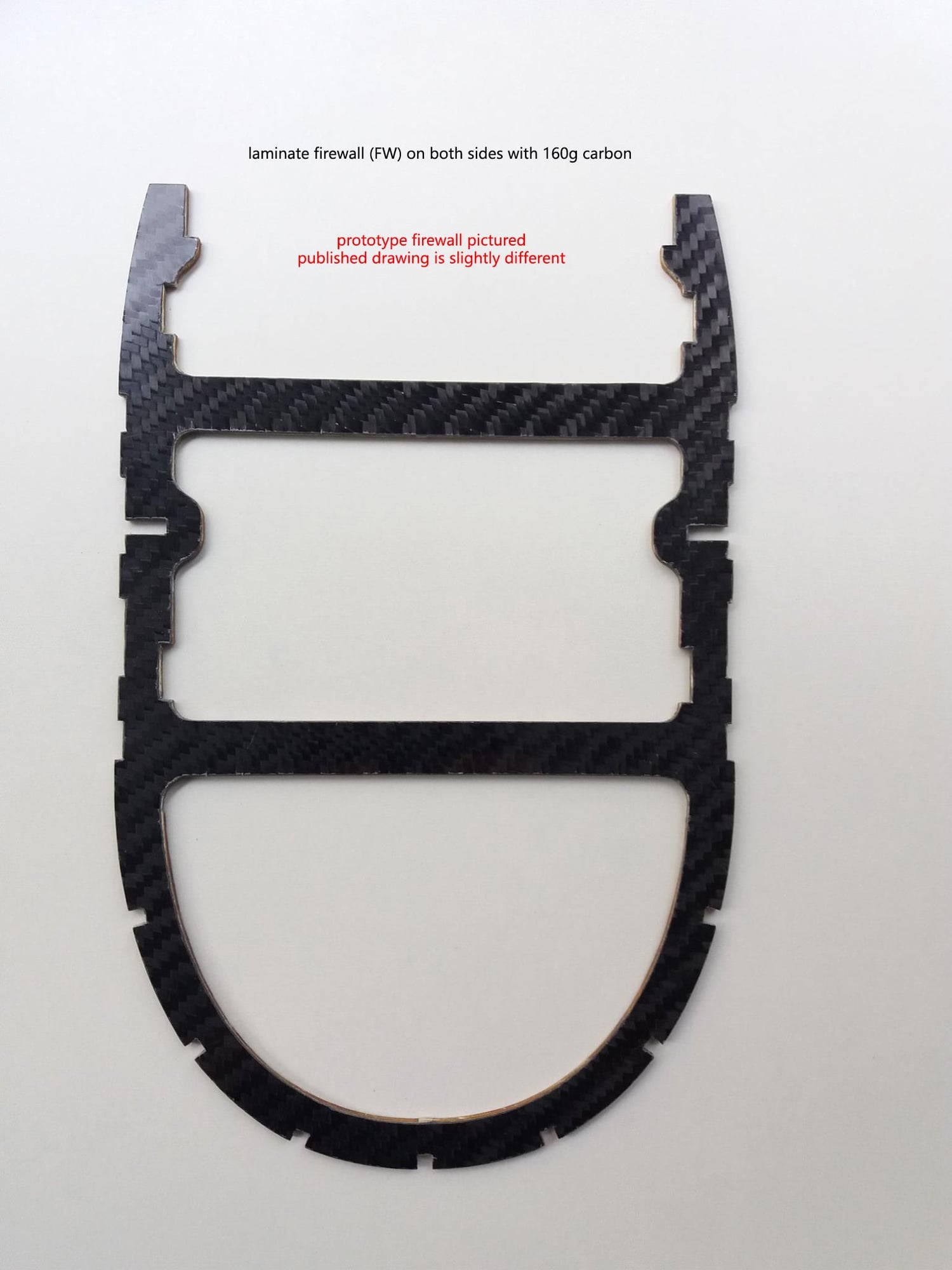
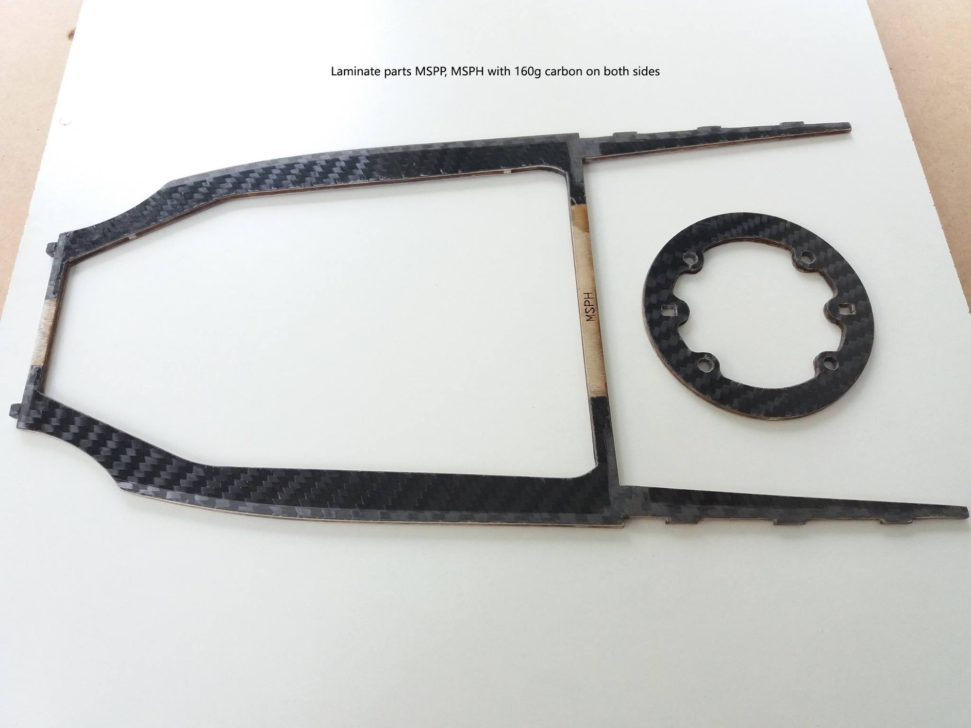
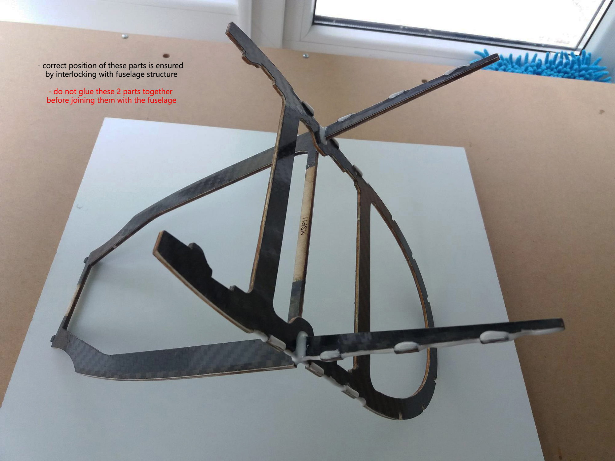
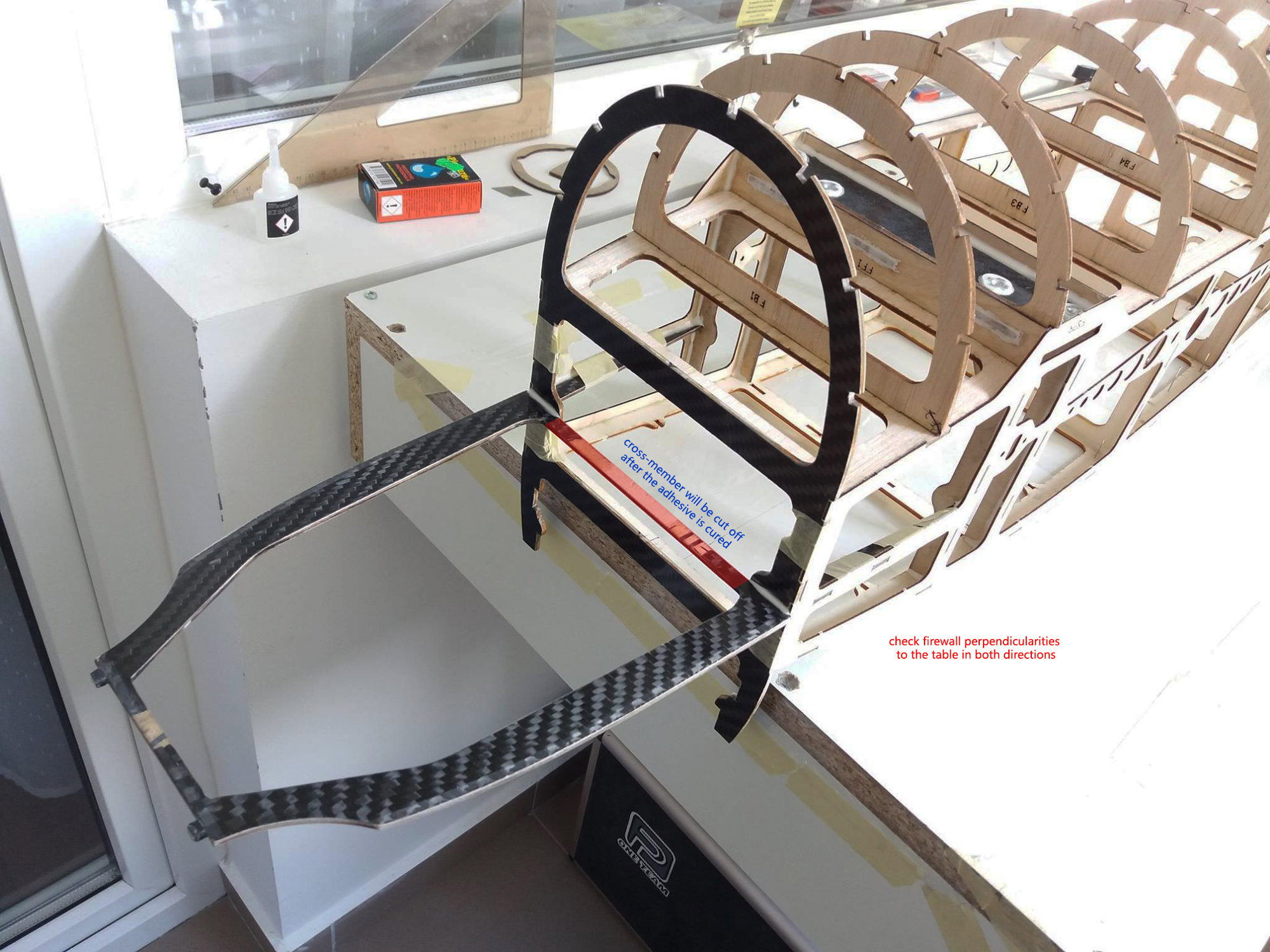
One of the fuselage frames (FB2-B) was added after building my prototype fuselage, so it's missing from my build photos but i added a CAD image to show it.
06-26-2019 | 04:08 AM
#18
My Feedback: (121)
Thanks Chuck! I know a few people who do laser cutting, but this would be an ambitious project for them - I'd rather not be the Guinea pig :-)
Maybe there would be enough interest to get a few kits cut (probably need to be pre-paid) which might lower the cost.
Thanks for the info Alex, 2mm is the only size that I can't source.
The build looks great!
Maybe there would be enough interest to get a few kits cut (probably need to be pre-paid) which might lower the cost.
Thanks for the info Alex, 2mm is the only size that I can't source.
The build looks great!
Last edited by flywilly; 06-26-2019 at 04:13 AM.
06-26-2019 | 04:52 AM
#19
Thread Starter
For the 2mm plywood, you can find 5/64 birch plywood here:
https://www.aircraftspruce.com/catal...nnishbirch.php
Alex
06-26-2019 | 08:34 AM
#21
My Feedback: (11)
Not sure if Mike would be interested in that or not. But going back and reading the thread on Alex's Audax am I absolutely floored at the level of detail he puts into hes design from a construction standpoint. If you pay close attention to the stab construction pics you can see how the rib and the jig are not cut from each other until you have completed the construction of the stab. This makes building significantly easier and more efficient. Really looking forward to building this plane!
06-26-2019 | 10:08 AM
#22
Thread Starter
The drawings are free so if anyone wants to cut kits and sell them it's perfectly ok, i don't want anything for me.
Unless there's someone willing to make an ARF model from this...in this case i would require 1-2 models for testing and personal use
Unless there's someone willing to make an ARF model from this...in this case i would require 1-2 models for testing and personal use
06-26-2019 | 11:48 PM
#24
Thread Starter
Thanks a lot Rune. The plan was to build and test the prototype before releasing the drawings, but after moving to Sweden last year it was impossible to continue. I managed to finish building all major parts but unfortunately the model is not tested yet. Maybe i'll be able to bring my planes and tools here but it will take a while.

