


Hangar 9 60cc Corsair
 04-17-2015, 01:55 PM
#1826
Senior Member
Join Date: Aug 2008
Location: ADDLESTONESURREY, UNITED KINGDOM
Posts: 321
Likes: 0
Received 0 Likes
on
0 Posts
Hi mirored.
I think that "Tom" may have the answers you are looking for...........I think that because of the "gap" most people have with regard to the centre section "fitting" against the fuzz,the dimension from say the tip of the prop to the leading edge of each wing will differ a little.
I think the better dimension to use,if trying to see the difference,may be from a point on the same blade,to say the centre point of the c o g position....marked on either side of the fuzz..?
Note : Tom stated in a reply that the "Keleo-Box" uses about half of the factory off-set and therefore,expect to use some rudder trim to compensate for this...?
I also think,but "Tom" has not given a reply to this,with regard to the off-set on the engine C / L position.........has this been moved over to the STD side more , to allow the #3 cylinder to fit into the cowl,with out the need for cut-outs...?
I will assume that the factory off-set to the right on the F/W,then gives a "setting" for the engine C / L off-set, to allow the "spinner" to be in the middle of the cowl,looking down from above...?
For the #3 cylinder to fit in the stock cowl,the engine C/L must have been moved......? chip in here Tom...?
Just my thoughts,but willing to be corrected !!!!
I think that the Keleo box is a great idea to lesson the amount of work that has to be done on the stock F/W to mount the 84............very neat and looks to be pretty quick retro-fit.
Kind regards.................Nick (UK).
 04-17-2015, 02:20 PM
#1827

My Feedback: (1)
Understood, and thanks. I am moving forward tonight on assembly of the mount and following his directions. If it takes a little more rudder, I am good with that. I am planning to use a demon cortex for stabilization (not looking for a debate on this one) and that will help to offset any differences, but still thumbs will have to work at it. I am using a Top Flite cowl which would hide the cylinders, I did this mostly due to the cutting of the firewall by the original owner and my uncertainty of the strength. It may very well have been very adequate, but this will give me the assurance I am looking for.
04-18-2015, 04:54 AM
#1829
Member
Join Date: Aug 2002
Location: WI
Posts: 35
Likes: 0
Received 0 Likes
on
0 Posts
Hi Mirored & Nick,
Sorry Mirored I don't have the information regarding the distance from the tip of the prop to the leading edge of the wing.
In regards to the engine C/L position, the engine C/L was moved over to allow the spinner to be in the middle of the cowl when looking down from above.
I'll try to post some pictures later today.
Tom
04-18-2015, 05:13 AM
#1830
My Feedback: (1)
Almost ready to secure the box with glue. I am using small screws to hold it in position while testing the fitment of the box. The center of the cowl is going to be hard to determine since the shaft passes through at such an angle that there is always a judgment on where it exits the cowl. I am not going to stress over it a whole lot and trust the directions for installing the box and tweak it to make it look best. There is definitely enough thrust to the right, I am looking at the down thrust as well. A lot to consider.
Andy
Andy
04-18-2015, 06:18 PM
#1832
My Feedback: (1)
Tom,
That answers a lot actually. I purchased a TF Corsair cowl which would have contained the cylinder heads within but the original cowl has the right thrust offset molded into it. I am going to use the original cowl after all which means I have a little more fiberglass work to do to fill In where the cylinder heads were cut out for. No big deal, but it is all coming together. Thanks for posting the pictures.
Andy
04-19-2015, 05:06 PM
#1833
Senior Member
My Feedback: (2)
Join Date: Jul 2008
Location: CHAMBERSBURG,
PA
Posts: 142
Likes: 0
Received 0 Likes
on
0 Posts
I've had some experience with electric retracts and have a theory as to why they fail to either retract or deploy. Basically, the retract motor is a DC motor operating a jack screw arrangement which should be an ingenious way to do the job. And, when everything works, it is! However, it seems to me, after some dis-assembly of the electronics portion of the gear mechanism, there are 2 power transistors or ic's (not sure which) that are used to supply the motor with the proper voltage at the correct polarity depending on which direction the jack screw should turn. When there's a failure, there's a high probability that one of the transistors or ic's has failed. The transistors or ic's are actually surrounded by their own heat sinks again making me feel I have the part that fails identified. There's no cure - the electronics portion is completely potted. I've experienced this with 2 servo mechanisms I received from Motion RC who sells a variety of ARF's made by "FMS". Most likely, the electronics portion of a lot of these mechanisms comes from the same factory in China. I would think after all this time with these mechanisms, there would be someone "over there" who would beef up that portion of the electronics.
04-20-2015, 04:37 AM
#1835
Member
Join Date: Apr 2012
Location: , TN
Posts: 44
Likes: 0
Received 0 Likes
on
0 Posts
This is my first attempt at fiberglass. Thanks to this thread and others on RCU I have learned a lot.
Already thinking about another project.
see you soon,
John
Already thinking about another project.
see you soon,
John
04-20-2015, 05:34 AM
#1836
Excellent job! Looking really good, I like the weathering too, not too light, not too heavy. Did you use cut vinyl for some of the panels (fuel cover panel, etc....)?

 04-21-2015, 04:54 AM
#1841
Member
Join Date: Apr 2012
Location: , TN
Posts: 44
Likes: 0
Received 0 Likes
on
0 Posts
I used aluminum duct tape for the panels .
see you soon,
John
Last edited by clover creek; 04-26-2015 at 05:30 AM.
04-22-2015, 06:17 AM
#1842

My Feedback: (63)
Join Date: Aug 2002
Location: Round Lake,
IL
Posts: 81
Likes: 0
Received 0 Likes
on
0 Posts
Silly question- but how are you guys fueling your Corsairs? A fuel dot on the side of the cowl was what I was thinking, but looking for other ideas as well. Thanks!
04-22-2015, 07:49 AM
#1843
My Feedback: (10)

Join Date: Apr 2002
Location: Tustin,
CA
Posts: 415
Likes: 0
Received 0 Likes
on
0 Posts
I used one from PSP Manufacturing (www.pspmfg.com) as they have blue anodized ones that were hardly noticeable against the blue of the cowl. I mounted it near the bottom of the cowl, so as not to be very visible. Only problem is, with the line lower than the tank, it can have a siphon effect when opening it up to fuel, but just pinching the line negates that somewhat. I only ended up with 1 tiny hole in the cowl for the choke rod used on the Saito FG-84.
04-22-2015, 08:48 AM
#1844
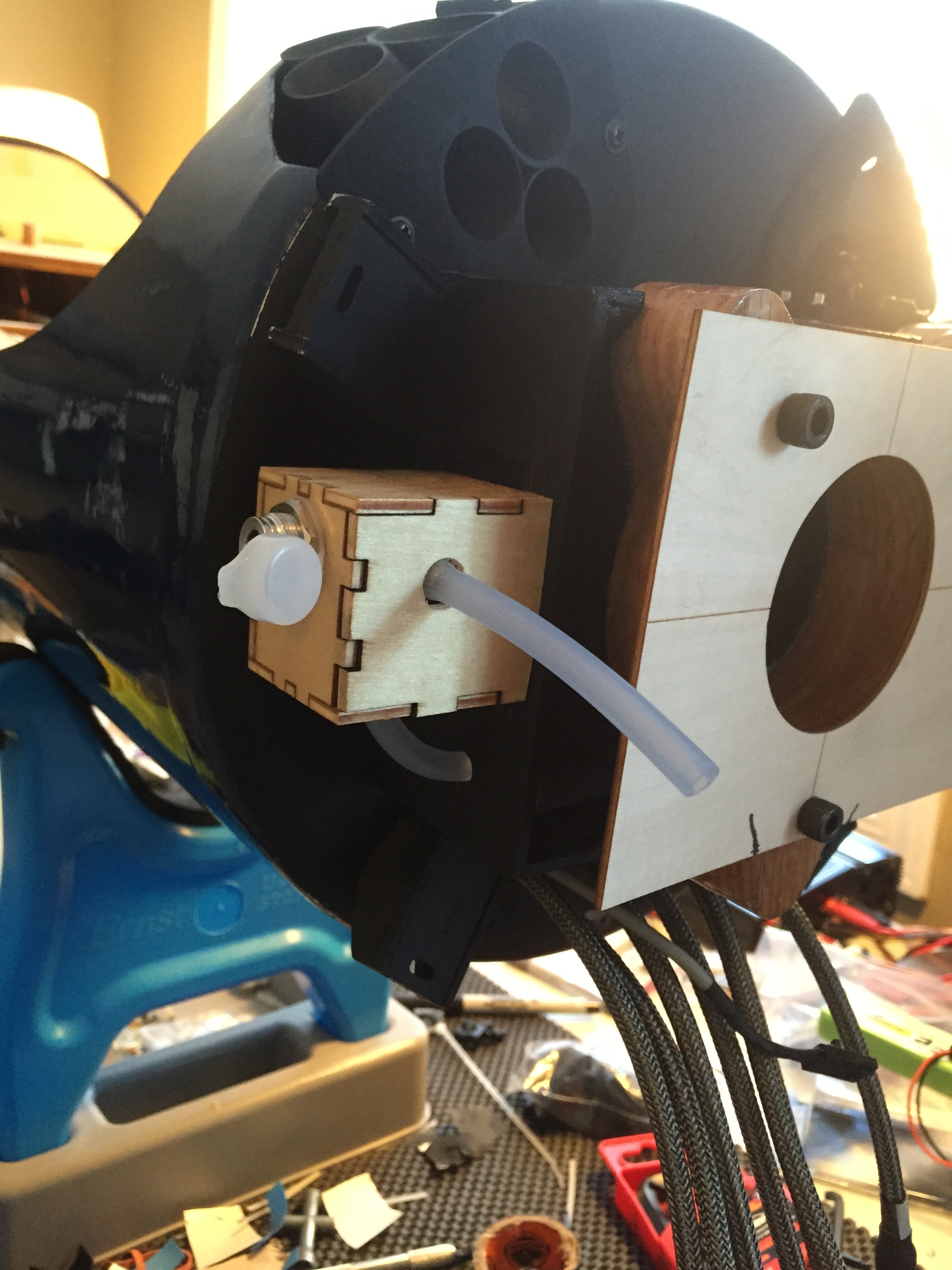
This is what I had come up with for the fuel-dot on my Corsair (note the pic is with the fuselage upside down). I cut one of the included weight boxes to the appropriate length and fastened it to the side of the firewall, and mounted my fuel filler valve inside the box. This way I was able to keep the level of the fuel line where it should be to prevent siphoning, and also be able to access it with the cowl on. You could use any fuel dot you'd like in this manner of course... also, I made sure the front "door" on the boxt fits tight but is still removable in case you need to get inside. I also secure it with a rubber band as well to make sure it doesn't vibrate lose during flight.
04-23-2015, 11:06 AM
#1846
I just ordered my retracts from Sierra, talked to Darrel and verified that these are specifically made for the H9 Corsair, they are not the P40 or Ziroli Corsair gear. I also ordered his 5" wheels and an air control kit from him. He said I should have them in hand by the end of next week, I'll keep on waiting. I'll post pics when I get them and once installed if anyone is interested.
Next thing to wait on is servos.... I'm going Savox 1267SG on control surfaces (overkill I know but that's the only way I know) but I'm going to use MKS HV6110 servos for the gear doors. They are high voltage compaitble thin wing servos a little spendy but should do the job nicely. My plan is to control them on a JR Xbus channel that way I can set center, end points, speed etc using only one radio channel for all 4 servos. This will be my first time setting up Xbus but it looks pretty simple. I'll also be using the JR Infinity receiver and Xport Xbus PWM converter (not in stock in the USA yet). Sounds like a lot of equipment but total weight of the receiver and converter is about 3oz and will give me total flexibility in the setup.
The hardest part about this plane so far is sourcing the equipment to go in it!
04-24-2015, 04:55 PM
#1848