1/18 chassis build need motor/gearing and tires for
 02-14-2023, 10:29 PM
#51

Thread Starter
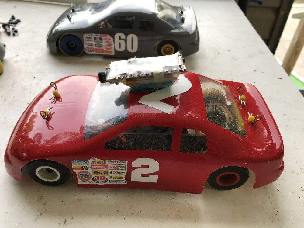
I have completed 4 cars now and they turned out great.
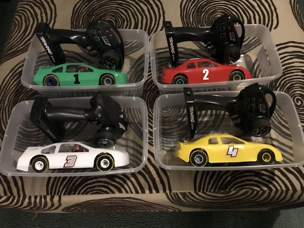
I have run hundreds of laps with each to be sure they perform as expected.
Notice the bubbles in the yellow car. (more on this in a moment)
The White car and the Green car were pulled from PETG. The Yellow car and the Red car were pulled from Lexan.
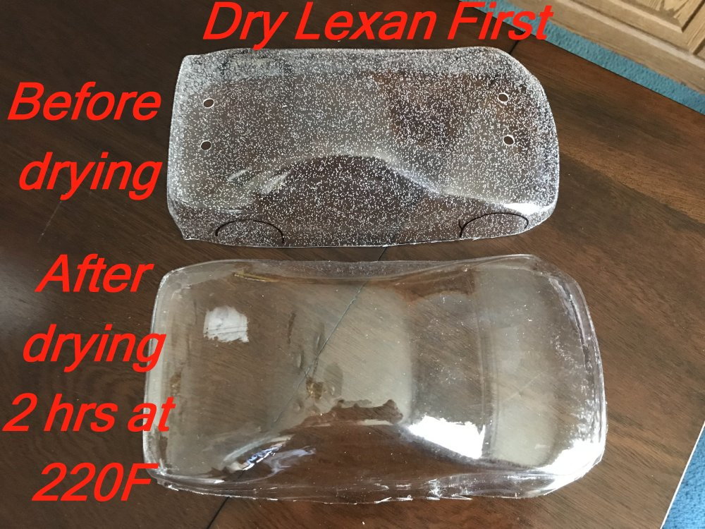
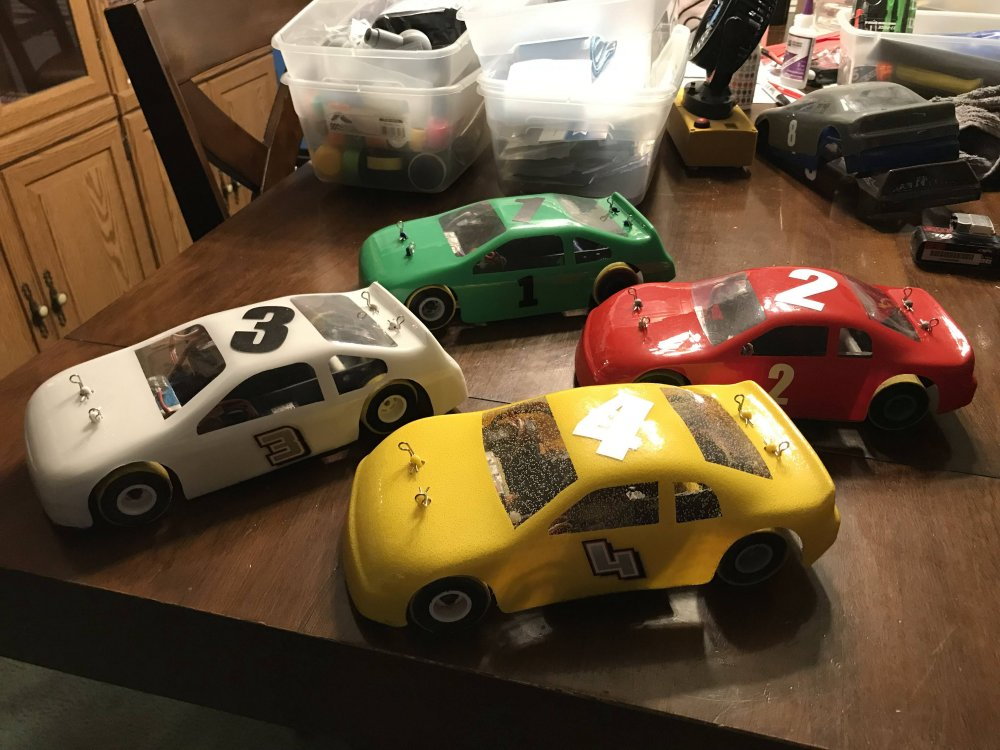
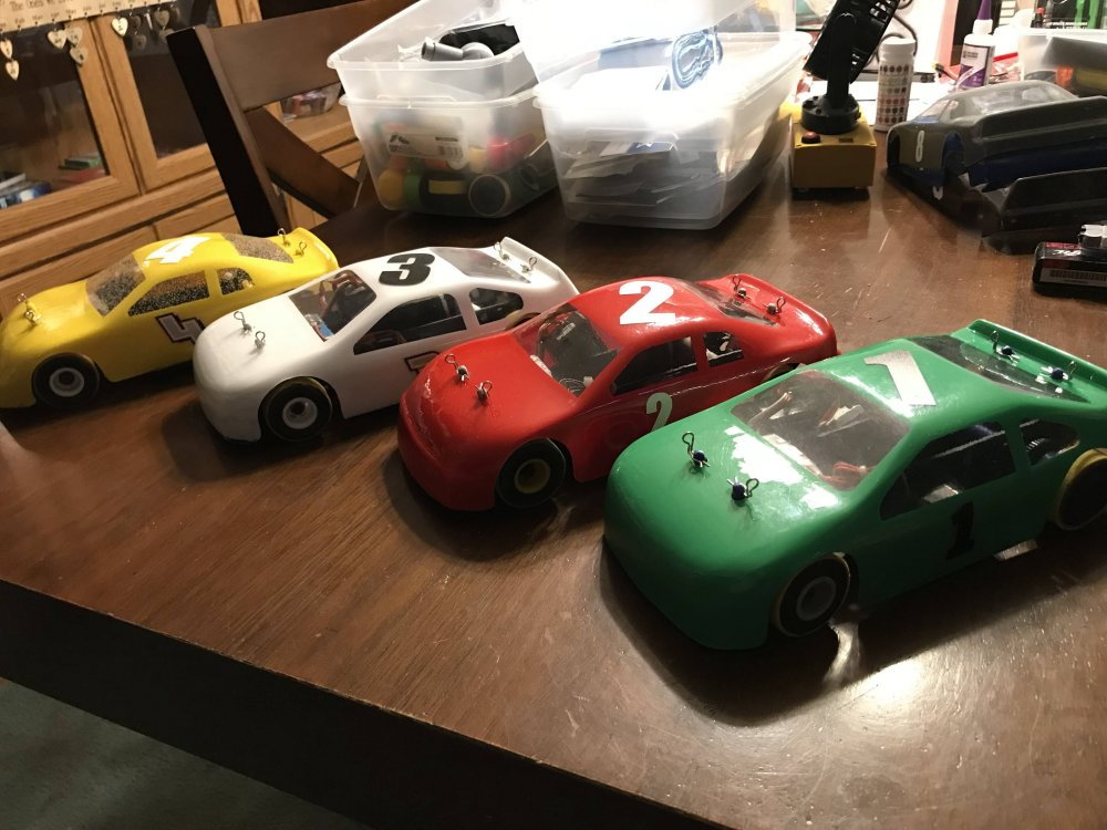
Here is a look at the bodies before they were painted. The Yellow body is the top one with all the air bubbles.
This happens because of moisture in the Lexan. To avoid this you need to dry the Lexan before you use it.
I did not dry the Lexan for the top body and you see the results. I did dry the Lexan before I pulled the second body and it came out great.
I removed the Lexan from the 220F oven and then heated it for the pull and you see the results. So I will be drying the Lexan before I use it moving forward.
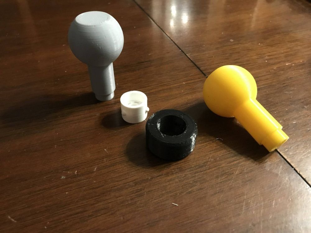
Here is a look at the tire tool I designed that makes it very easy to remove a TPU tire from the rim. It can also be used to remove a TPU tire from a rim that is mounted on the car.
Here is a short video showing how to use the tire tool.
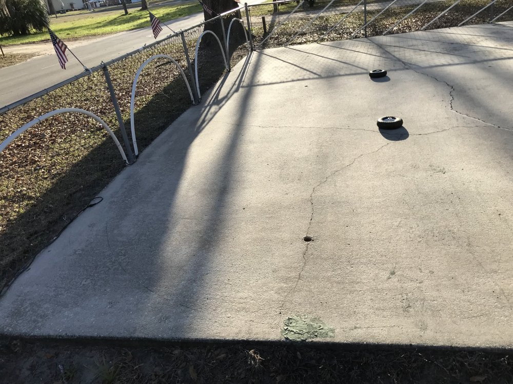
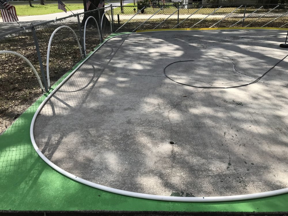
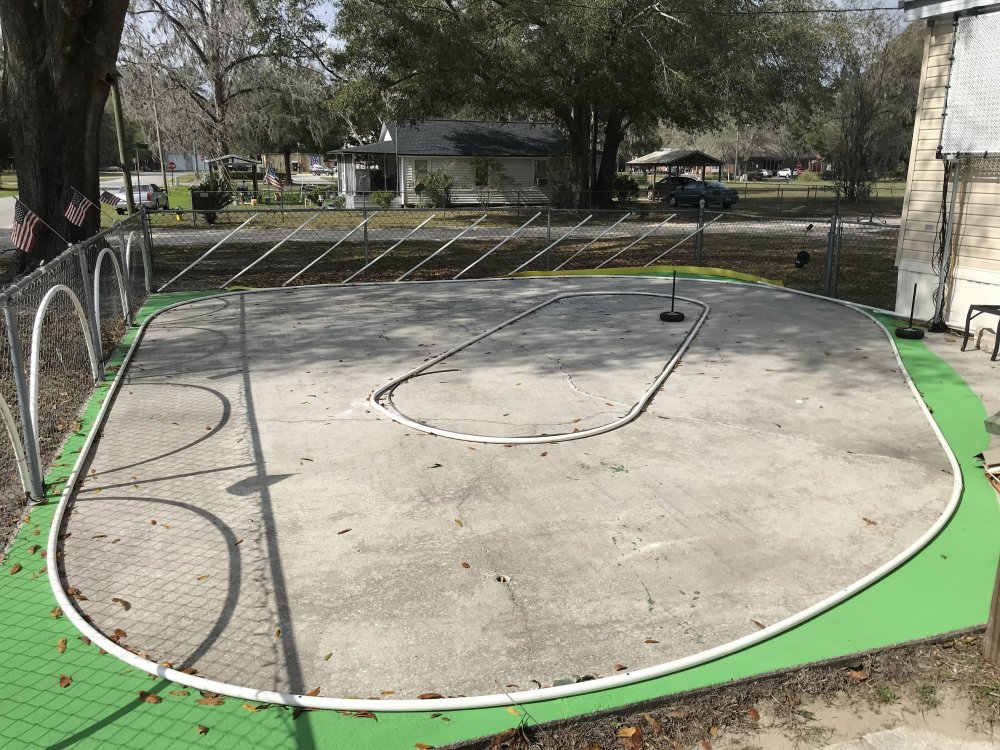
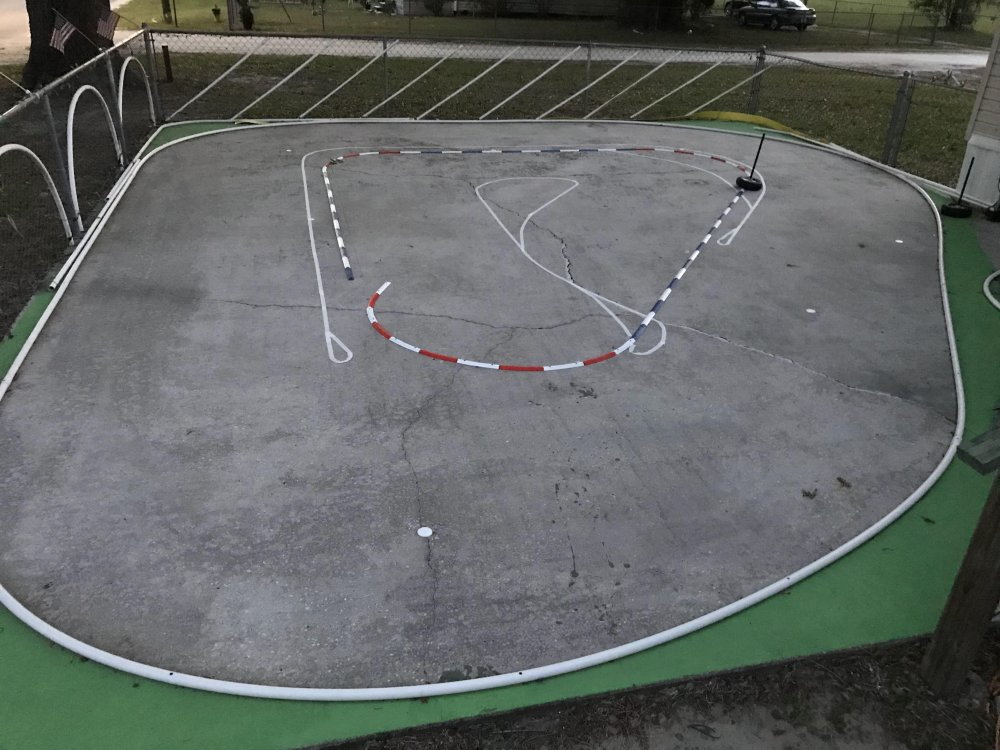
Here is a look at the concrete before I started the track layout.
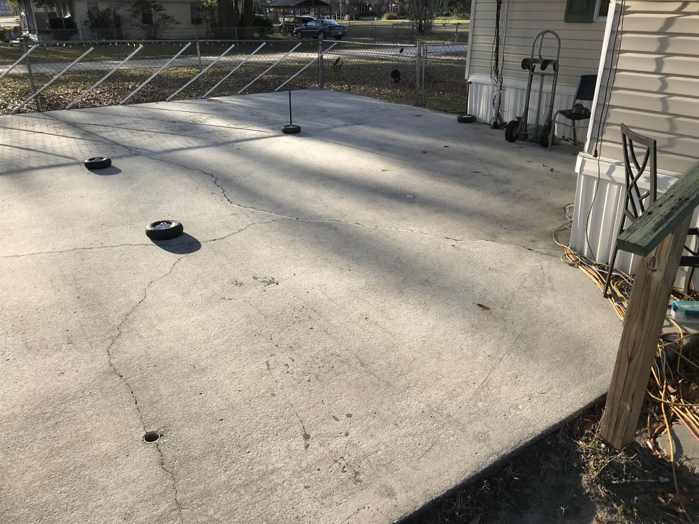
Race Track Coming Soon.
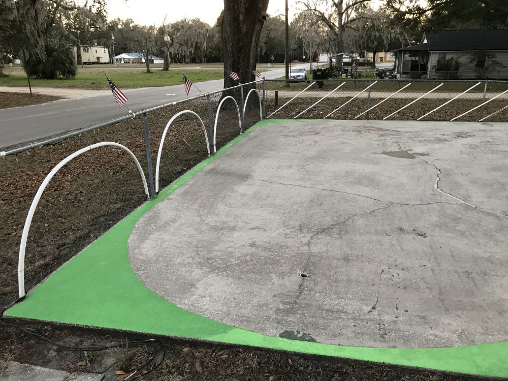
I laid out the track design and painted the outside of the track Green. The dark green is almost dry. The lighter Green is still wet.
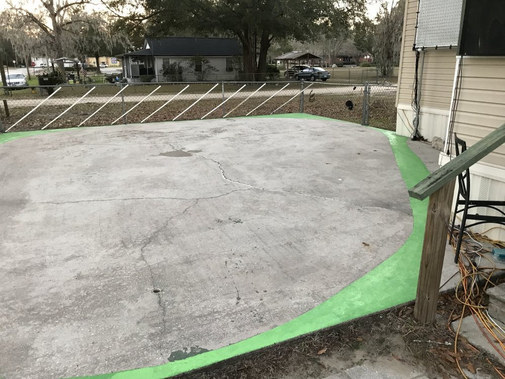
I used a oil base concrete paint.
I have completed the outside wall (1" thin wall PVC) and have started on the inside wall which will be 1" thin wall PVC
and 3/8' hose. The 1" thin wall PVC will be setup so that it can be flipped over to create a longer track layout which will add another turn
to the layout. More on this later.
I have run hundreds of laps with each to be sure they perform as expected.
Notice the bubbles in the yellow car. (more on this in a moment)
The White car and the Green car were pulled from PETG. The Yellow car and the Red car were pulled from Lexan.
Here is a look at the bodies before they were painted. The Yellow body is the top one with all the air bubbles.
This happens because of moisture in the Lexan. To avoid this you need to dry the Lexan before you use it.
I did not dry the Lexan for the top body and you see the results. I did dry the Lexan before I pulled the second body and it came out great.
I removed the Lexan from the 220F oven and then heated it for the pull and you see the results. So I will be drying the Lexan before I use it moving forward.
Here is a look at the tire tool I designed that makes it very easy to remove a TPU tire from the rim. It can also be used to remove a TPU tire from a rim that is mounted on the car.
Here is a look at the concrete before I started the track layout.
Race Track Coming Soon.
I laid out the track design and painted the outside of the track Green. The dark green is almost dry. The lighter Green is still wet.
I used a oil base concrete paint.
I have completed the outside wall (1" thin wall PVC) and have started on the inside wall which will be 1" thin wall PVC
and 3/8' hose. The 1" thin wall PVC will be setup so that it can be flipped over to create a longer track layout which will add another turn
to the layout. More on this later.
Last edited by testfly; 02-14-2023 at 10:34 PM.
 02-16-2023, 09:51 PM
#52
Thread Starter
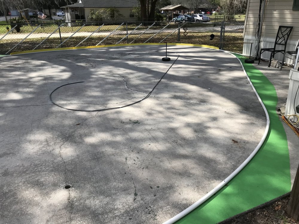
1" thin wall PVC was used for the outside walls. I am not sure if I will use the Yellow wall yet or not. It is just laying where you see it so that it is out of the way for now.
I may attach it to the fence so if a car jumps the PVC pipe it can hit the plastic wall before it gets to the wire fence.
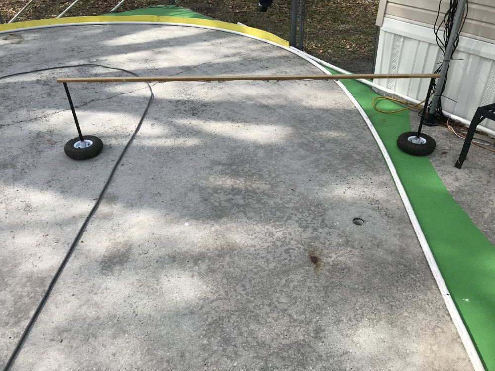
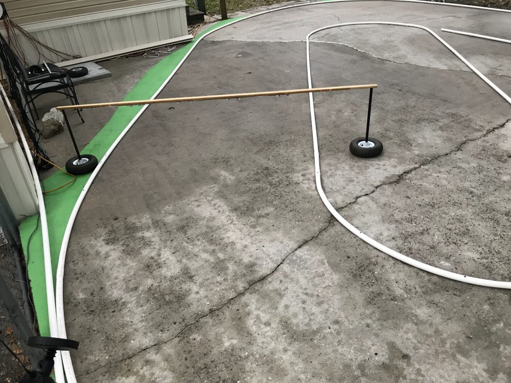
Here you can see the timing bridge. The top is a 1x2x8 PT. It is stored out of the weather when the track is not being used. It lifts off the post using no tools.
The scoring pickups are mounted to the bottom of the 1x2 and so far the timing system has not missed a lap.
After turning a lot of hot laps today I think I will do all of the inside wall with the 1" thin wall PVC and not use the small hose at all.
I will heat the 1" pipe before bending the tighter turns. There was no need to heat the PVC pipe when I put it down for the outside walls.
NOTE: The holes you see in the concrete were used with the G scale train layout that I had poured the concrete for almost 30 years ago.I will cover the holes before the racing starts.
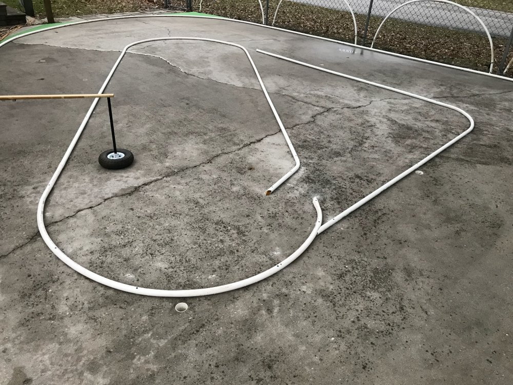
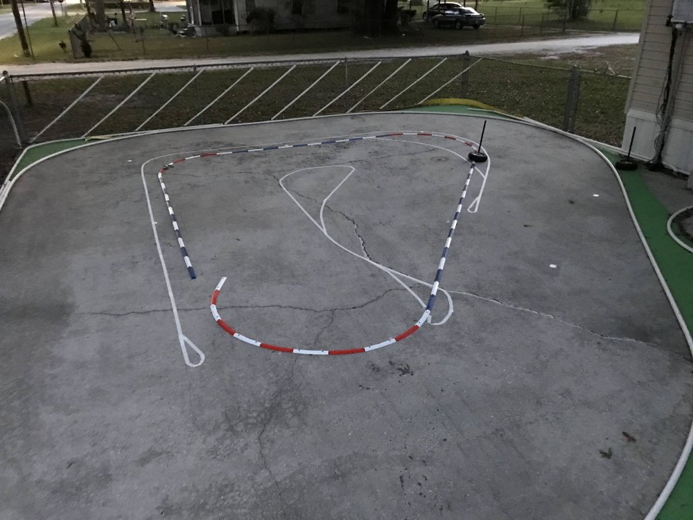
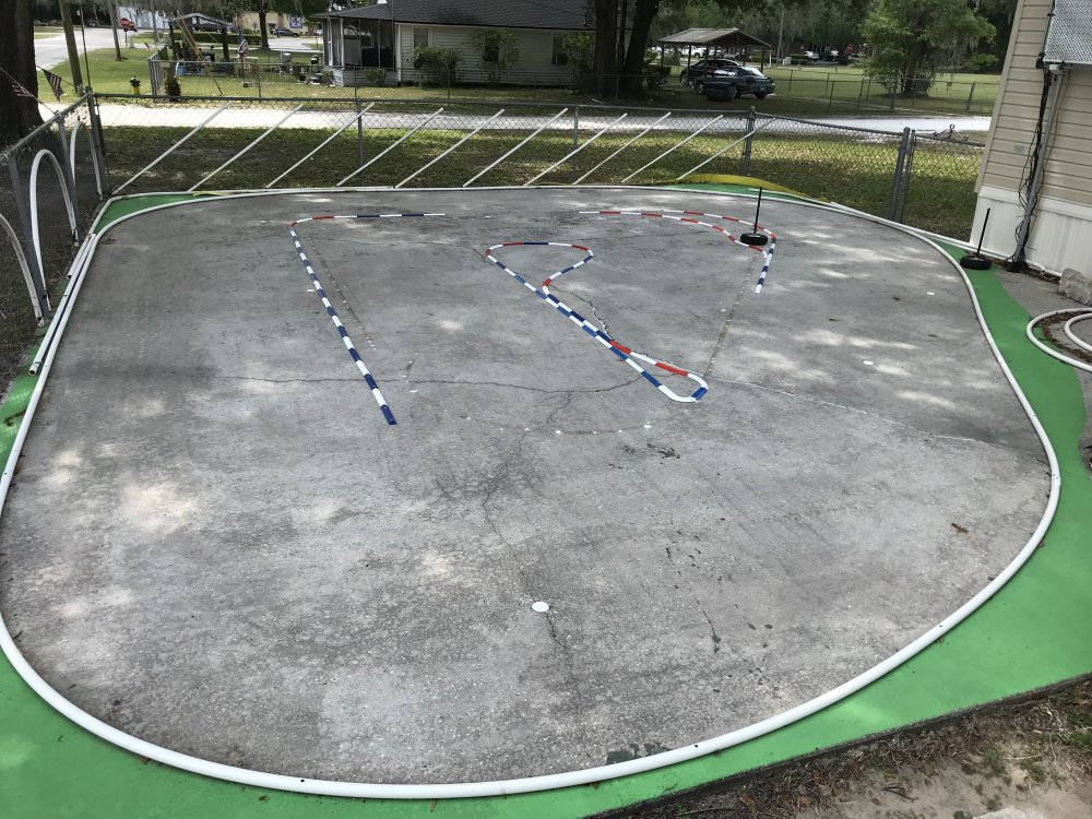
I cut, heated and formed the 1" thin wall PVC inside walls tonight and will secure them tomorrow. Though it was dark, I did get a few pictures of the layout.
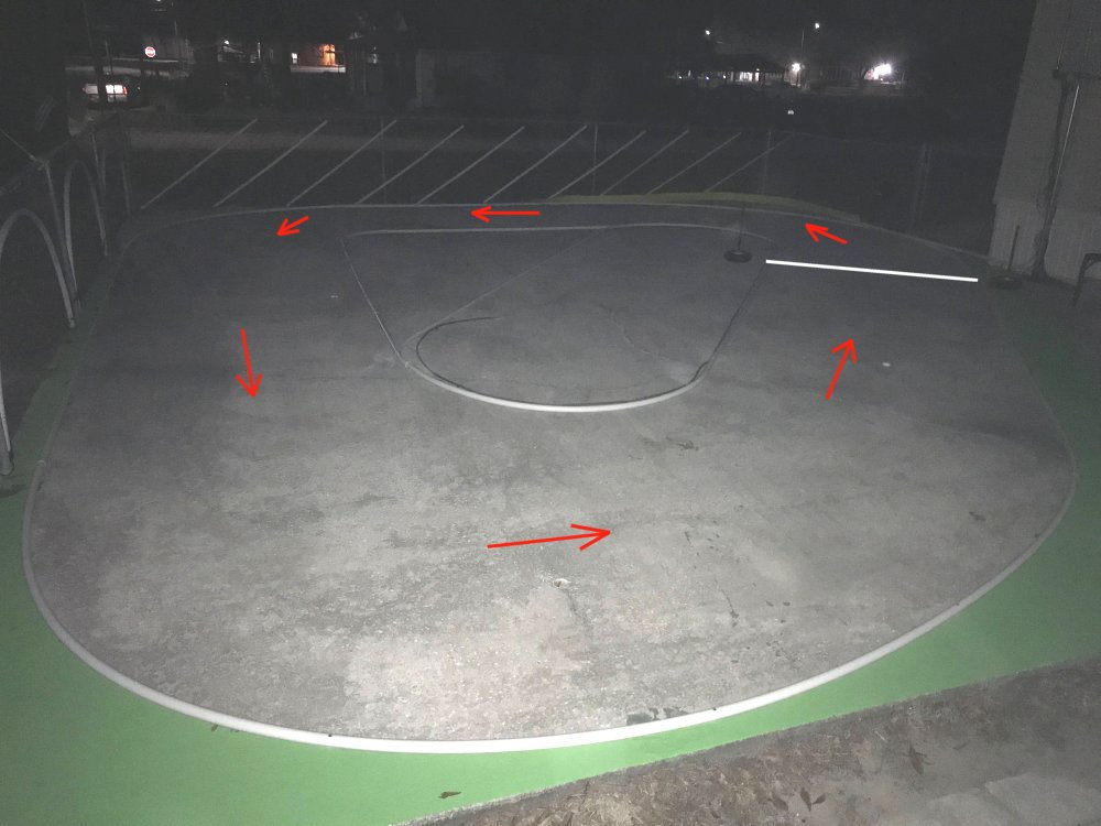
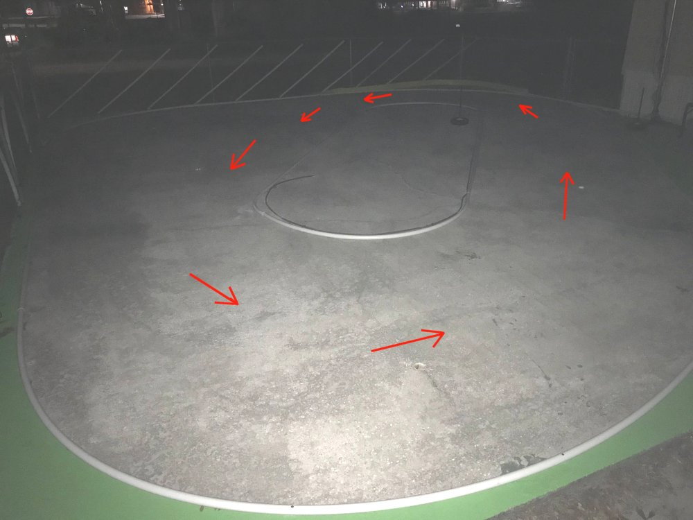
Here is a look at the longer track design. It should have a good flow to it. The start/finish line is the bright white mark at top right.
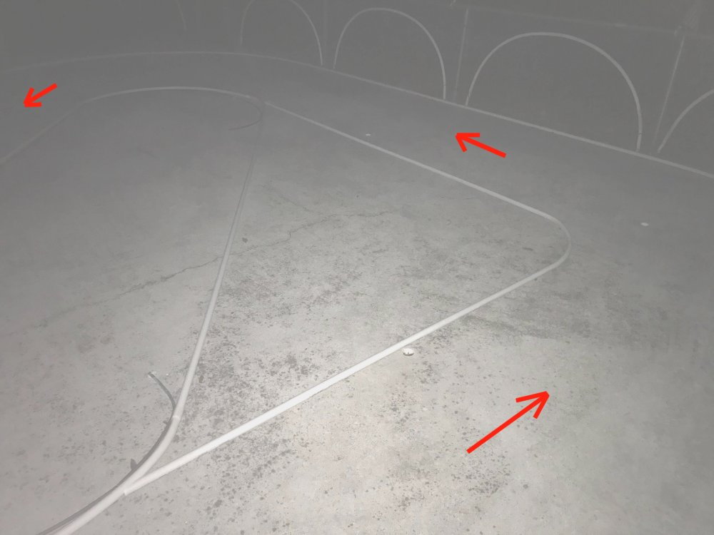
Here is a look at the inside wall that is removable. Having it in place adds a 90 degree left turn and 28' to the race center line.
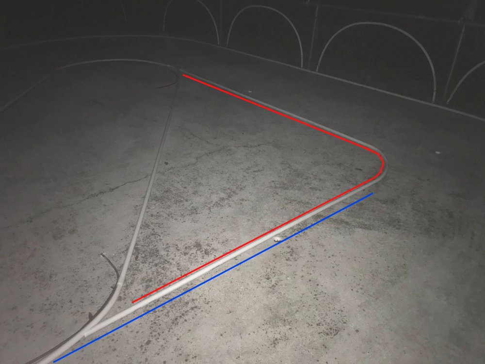
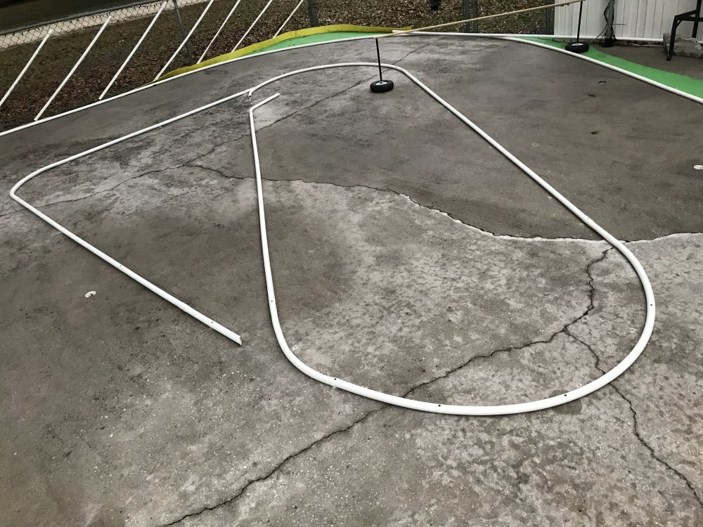
The blue line shows the inside wall flow and you can see that I have the wall seam set well inside the wall flow line. The red line shows the inside wall that can be removed
to change the track layout to the Oval for a little faster race.
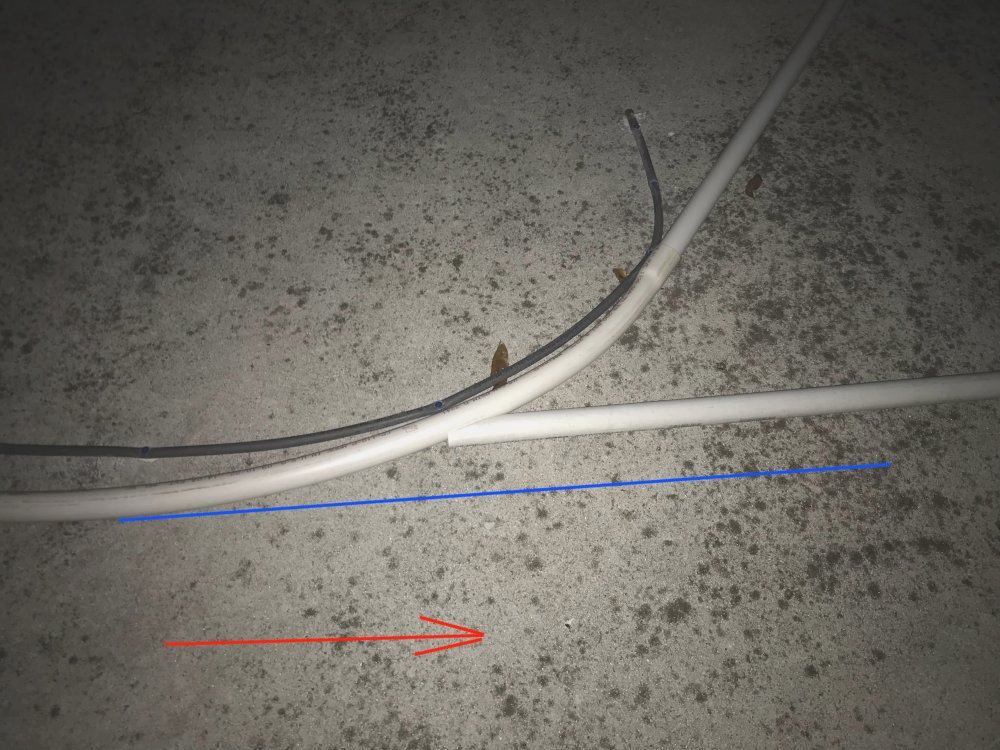
The inside wall seam is set back so it is not likely a car would ever hit that wall seam. Red is race flow and the Blue line shows how much the seam is set back from it.
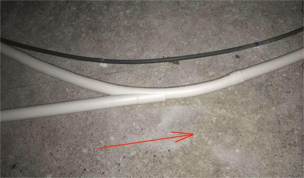
Here is a look at the other wall seam of the removable inside wall. This seam runs with the race flow so there was no need for any set back.
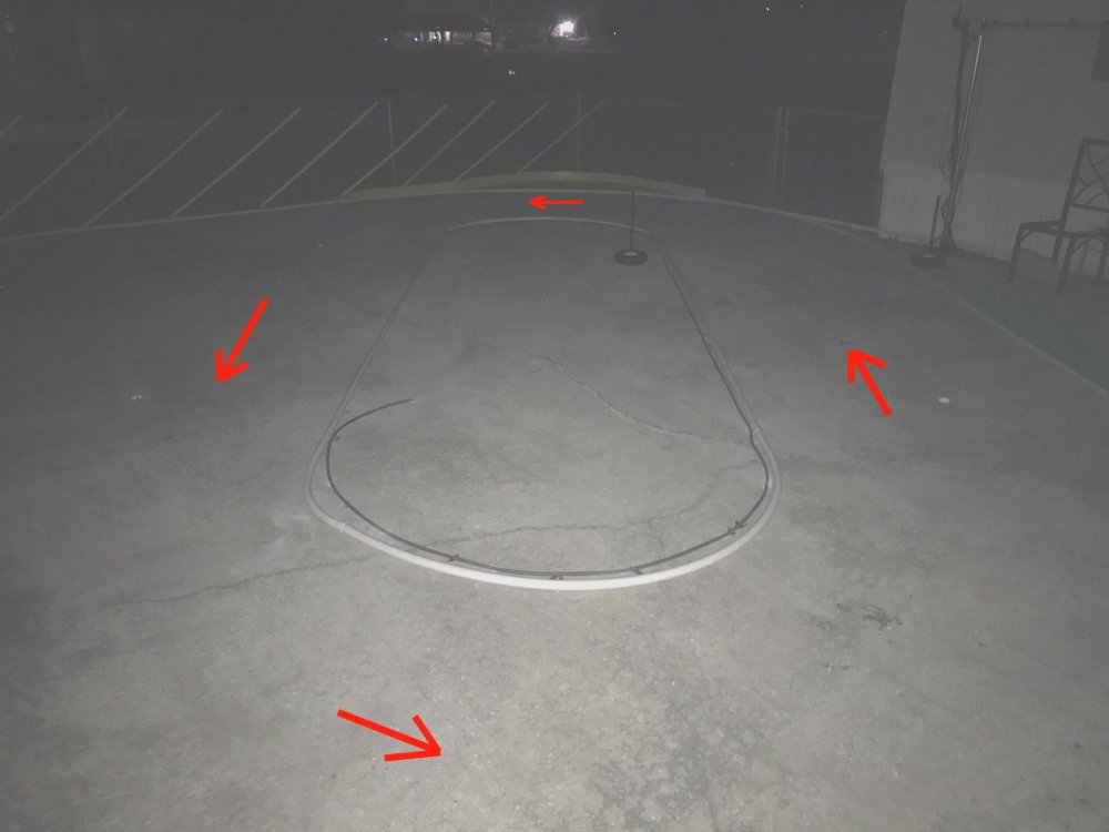
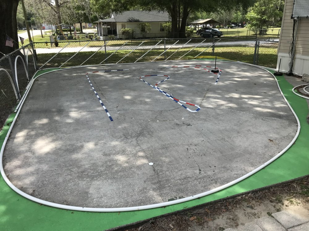
Here is a look at the Oval layout with the removable wall removed. I will be removing the hose you see laying inside the PVC inside wall.
I am looking forward to seeing a Sprint car running on the Oval layout. That is the only reason I wanted to have an Oval layout. So now I have to design a sprint car for sure.
The cars look & run great and at 6' wide the track is the perfect size for them. I will get a few pictures of the track before it gets dark tomorrow.
 02-17-2023, 06:47 PM
#54
Thread Starter
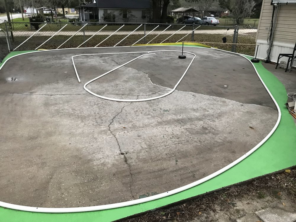
We had a lot of rain today but I was able to get the inside walls completed.
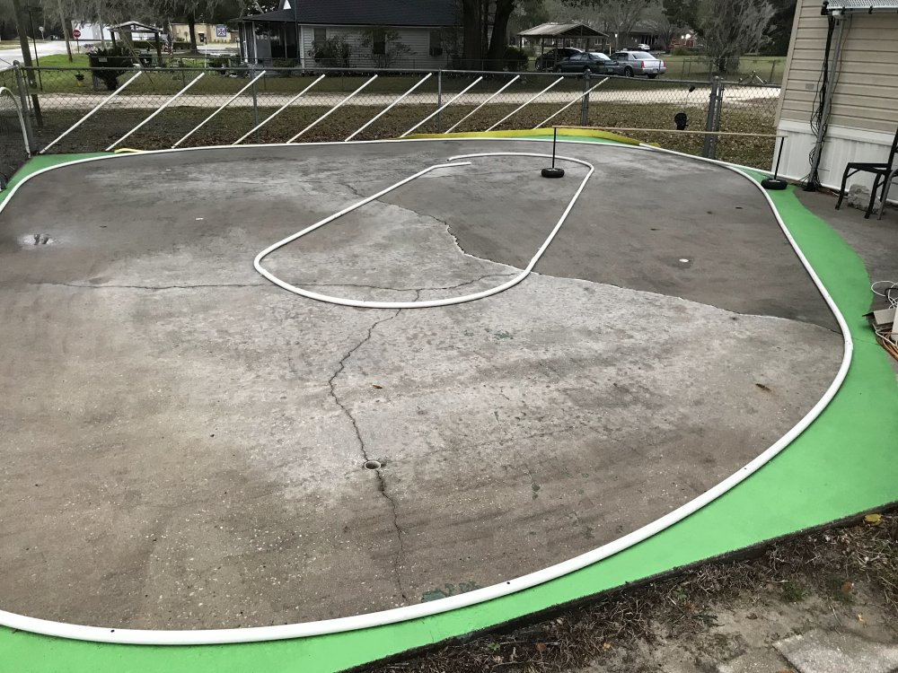
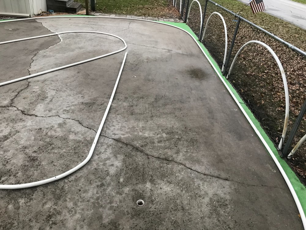
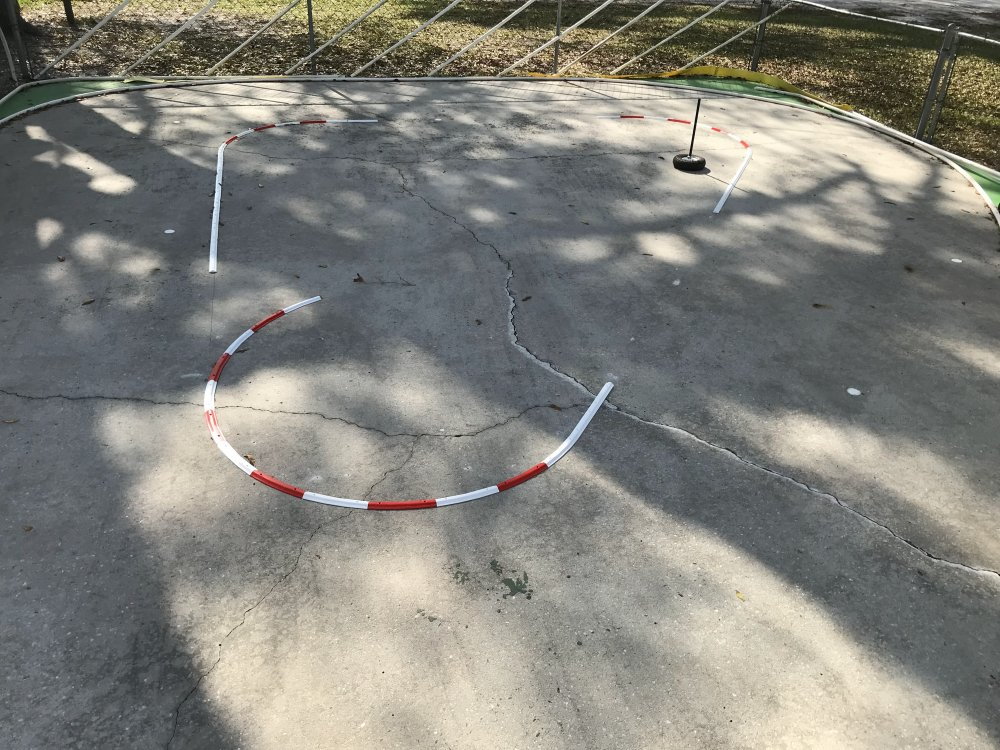
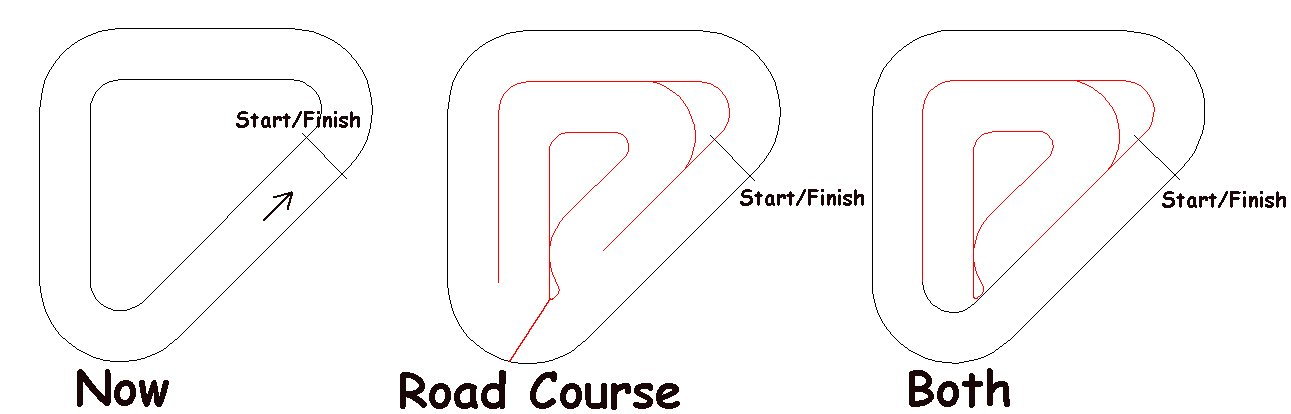
Here is a look at the Oval layout. Note: there is a way for a car to get back on the track if it does go over the inside wall.

Here is a look at the larger track layout. Adding the inside wall section adds a 90 degree left turn and 28' more track at the center line.
Note that a car that gets over the inside wall has a way to get back on the track.
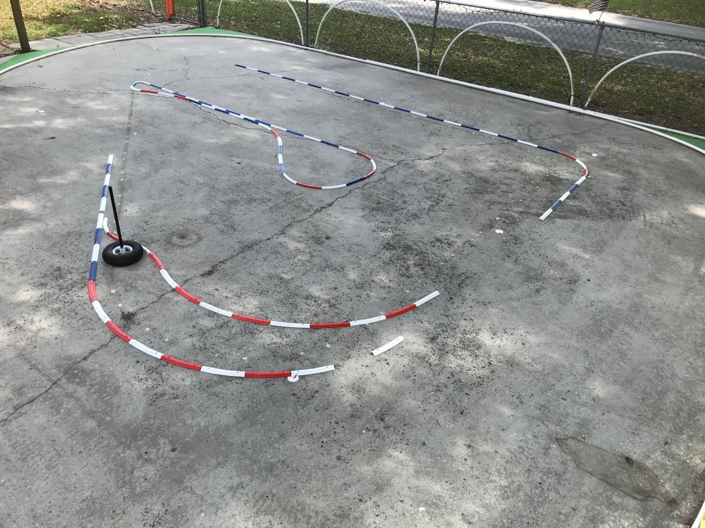
Here is a closer look at how a car that goes over the inside wall is able to return to the track without any issue.
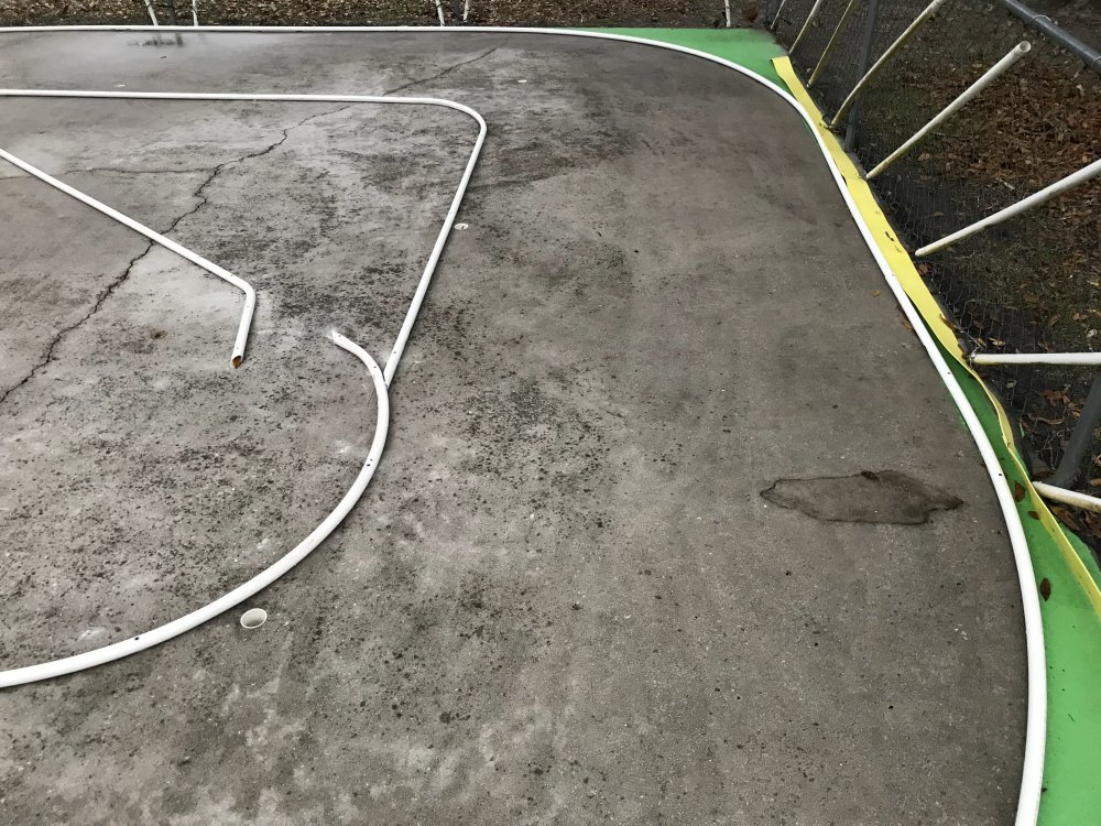
The yellow wall (picture right) is just laying there at the moment. I will be attaching it to the fence line soon if I do use it.
The PVC holes will be plugged before the racing starts.
The concrete pad is almost 30 years old and has a few cracks. The cracks do not effect the cars. But, they do help dry the track quicker after it rains. So that is a plus for sure.
I was able to get the inside walls done but I was not able to run any laps today because of the rain.
Below is a short video on how I bent and or formed the 1" thin wall PVC pipe used for the inside walls of the track pictured above.
I should have a hot laps video up in a day or two.
Here is a look at the Oval layout. Note: there is a way for a car to get back on the track if it does go over the inside wall.
Here is a look at the larger track layout. Adding the inside wall section adds a 90 degree left turn and 28' more track at the center line.
Note that a car that gets over the inside wall has a way to get back on the track.
Here is a closer look at how a car that goes over the inside wall is able to return to the track without any issue.
The yellow wall (picture right) is just laying there at the moment. I will be attaching it to the fence line soon if I do use it.
The PVC holes will be plugged before the racing starts.
The concrete pad is almost 30 years old and has a few cracks. The cracks do not effect the cars. But, they do help dry the track quicker after it rains. So that is a plus for sure.
I was able to get the inside walls done but I was not able to run any laps today because of the rain.
Below is a short video on how I bent and or formed the 1" thin wall PVC pipe used for the inside walls of the track pictured above.
I should have a hot laps video up in a day or two.
03-04-2023, 05:11 PM
#57
Thread Starter
The track layout is just what I was looking for. It is fast and the flow is nice.
So I wanted to design a wall system that was safer for the cars during a impact with the inside wall.

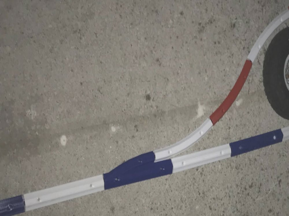
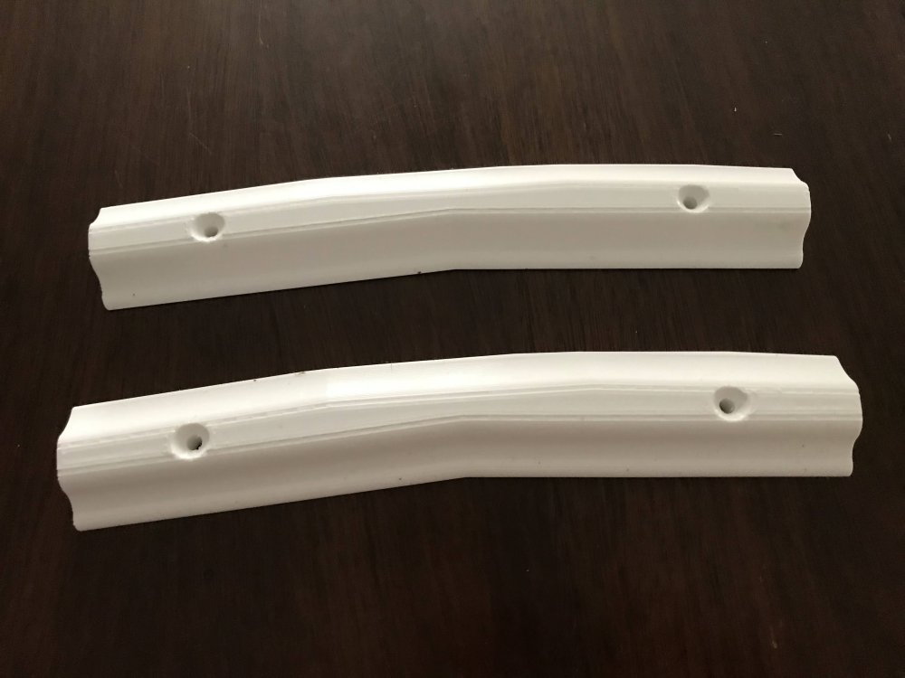
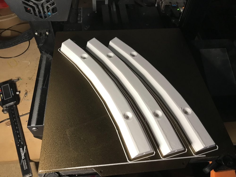
Here is a look at what I have come up with. The idea is the car will go over the wall rather then bounce off it. I have removed the inside PVC walls and will be replacing them with the 3D printed design.
The sections are 9". The curve radius is 36" as that is what my layout design uses for the inner walls.
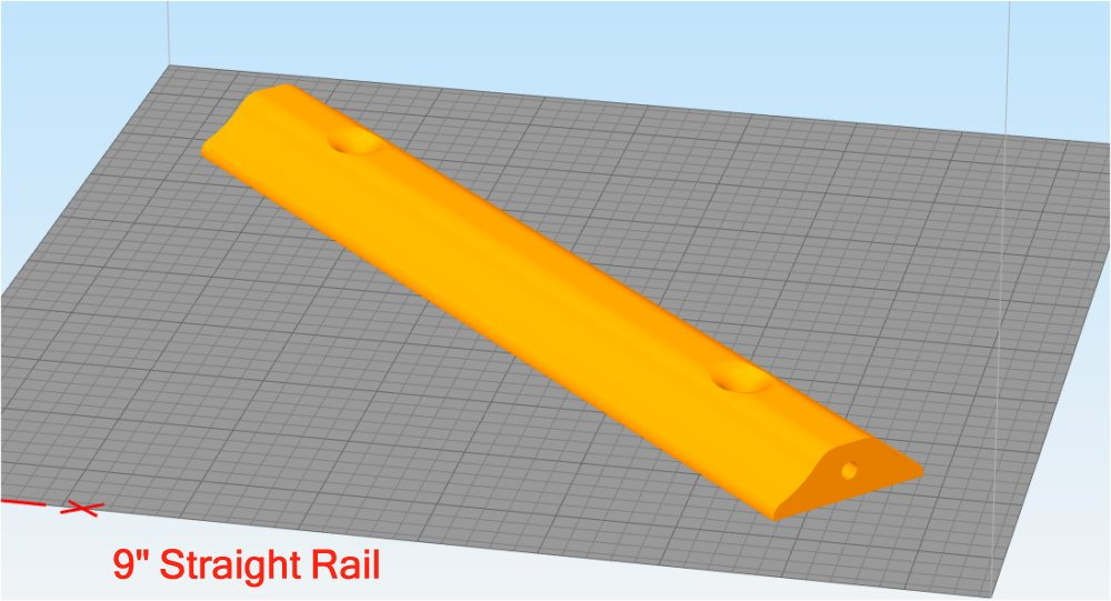
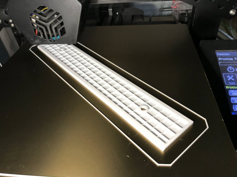
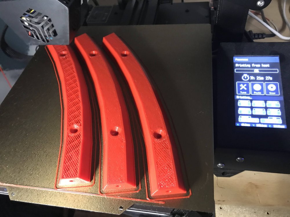
Here is the straight rail as it is being printed.
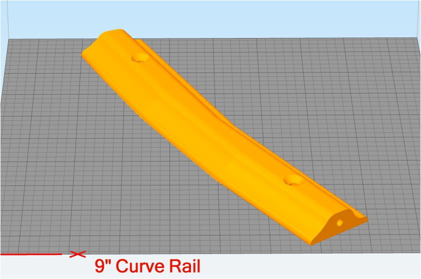
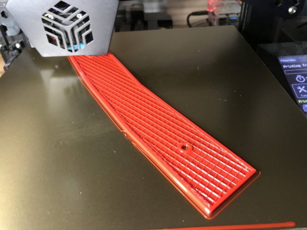
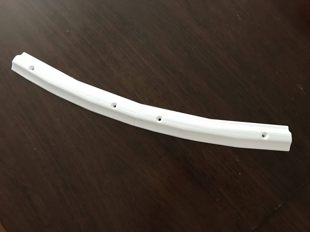
Here is the curved rail as it is being printed.
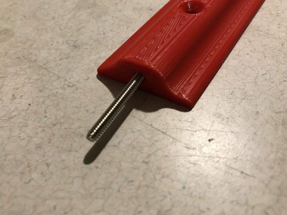
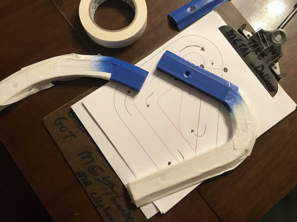
The ends of each section are designed to fit either a straight or curved section. The hole is sized for a slip fit of a 2" long 6/32 stainless steel screw. I cut the head off of the screw
so it can be used as a connecting guide. Using a stainless steel screw means there is no rust stains later.
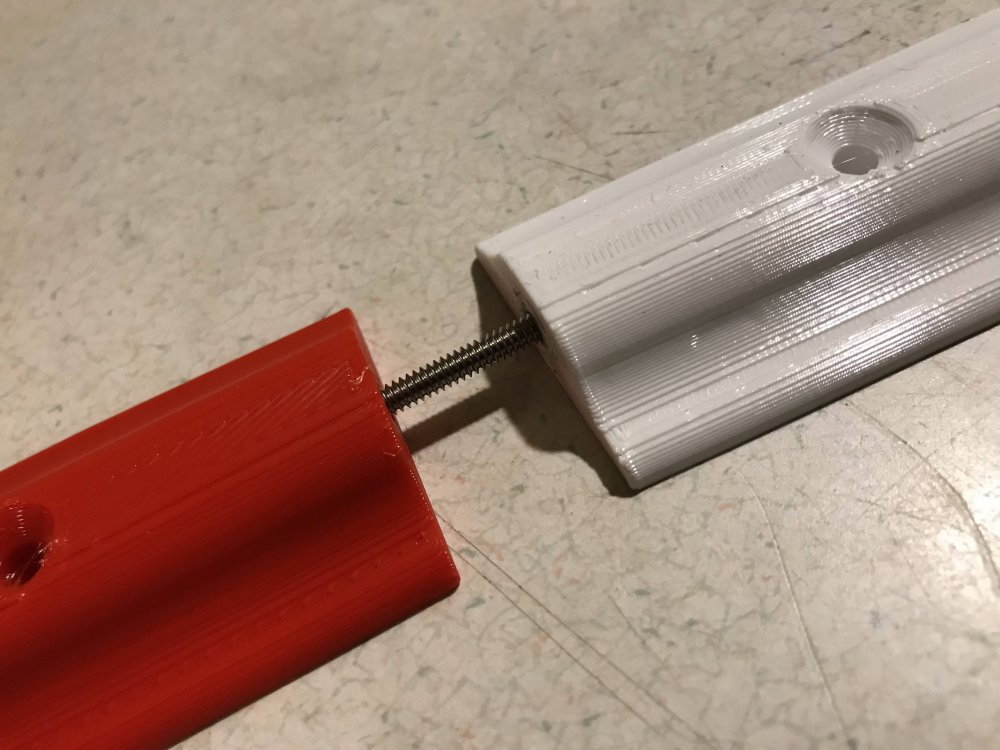
Here you can see how the sections are forced to align by the screw as they are put together.
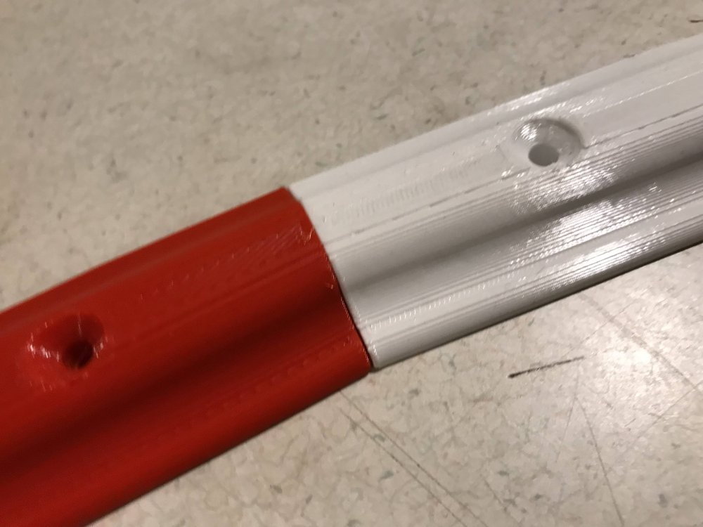
I will leave a 1/16" gap at each section to allow room for expansion and contraction.
I am printing the sections in white and red so no painting will be needed.
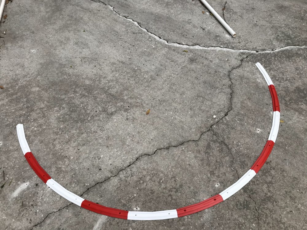
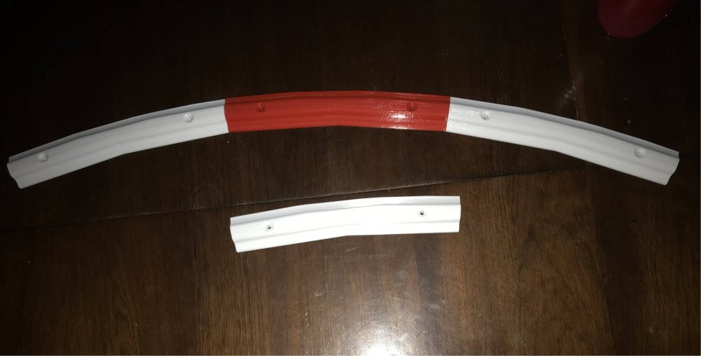
Here is a look at one of the corners as it is being test fit.
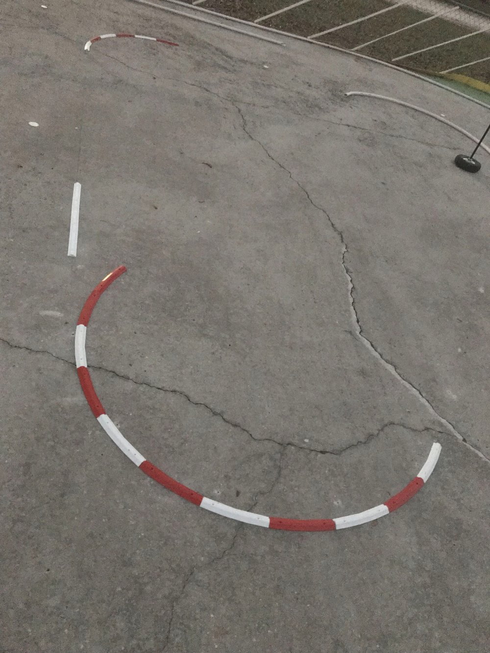
The new custom inside wall is going to look great when it is done. I do not want to use this wall design on the outside walls because of the chain link fence. So for now the
outside wall will remain PVC pipe.
I have my 3D printers printing red and white wall sections 24 hrs a day at the moment. I should have the inside walls printed and installed in 2 to 3 days.
03-07-2023, 09:01 PM
#58
Thread Starter
The 3D printers are working overtime and it won't be long now until I have the inside walls printed.
I have been joining the wall sections as they were printed. Once I have all of them printed I will use Tap-cons to attach them to the concrete. I will add a small gap between
each section to allow for movement and help to avoid any buckling in the wall sections.
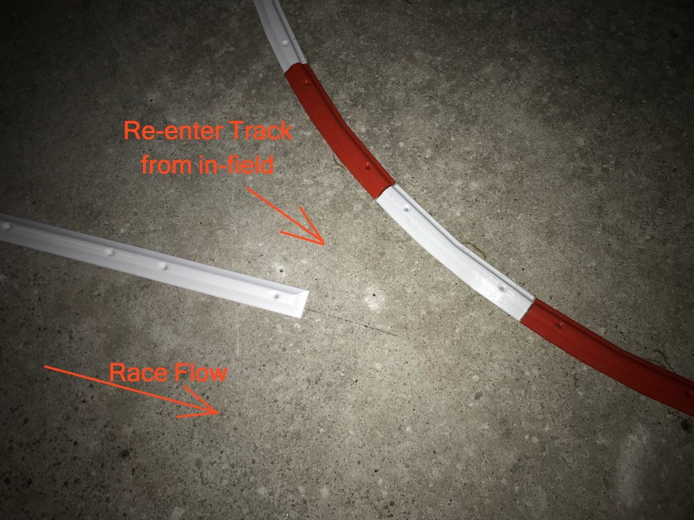
Here is a look at the only re-entry point for any car that gets over the inside wall and needs to get back on the track.
I have been joining the wall sections as they were printed. Once I have all of them printed I will use Tap-cons to attach them to the concrete. I will add a small gap between
each section to allow for movement and help to avoid any buckling in the wall sections.
Here is a look at the only re-entry point for any car that gets over the inside wall and needs to get back on the track.
 03-31-2023, 05:54 PM
#61
Thread Starter
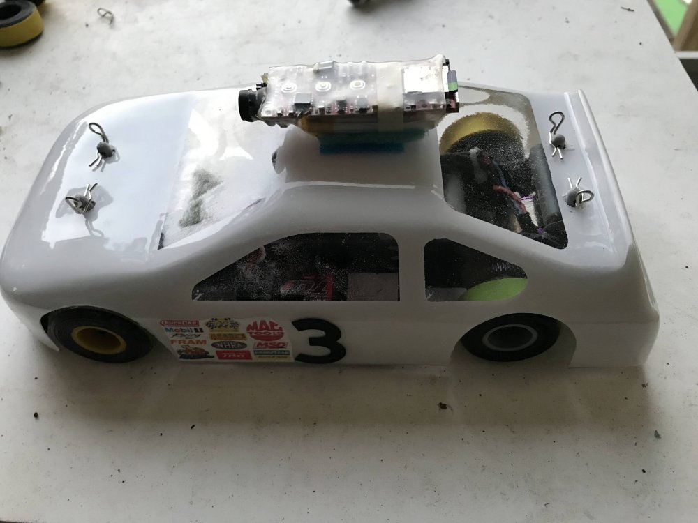
I have 3D printed 7 cars and 4 of them are built and running hot laps. The 3D printed parts are holding up very well.
My tire design is printed in TPU and capped with EPDM rubber and is working very well on concrete.
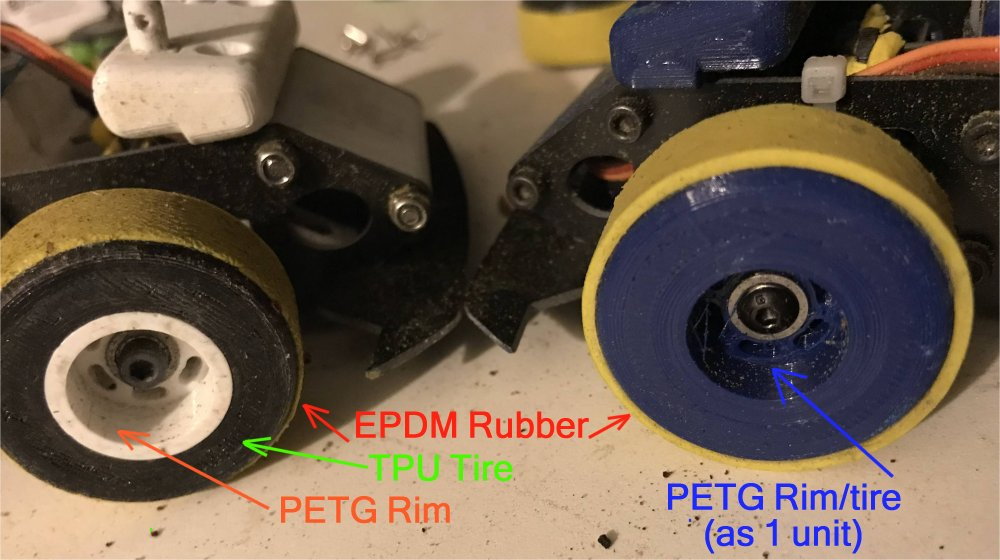
I have just printed the front rim and tire as one unit in PETG and capped that with the EPDM rubber and it seams to work just fine.
The PETG rim/tire is being tested on car #4. Hot laps of that car are coming soon.
Here is video of hot laps of car #1 with onboard video.
My tire design is printed in TPU and capped with EPDM rubber and is working very well on concrete.
I have just printed the front rim and tire as one unit in PETG and capped that with the EPDM rubber and it seams to work just fine.
The PETG rim/tire is being tested on car #4. Hot laps of that car are coming soon.
Here is video of hot laps of car #1 with onboard video.


 04-01-2023, 02:14 PM
#63
Thread Starter
I will create a "tighter radius wall section" and lay out a road course when I get more time for sure.
The key to a road course is to not over power the car. It is fun to see them run fast but fast does not go so well in the slow section of the track.
So I try and find a balance until I can better control the throttle finger. LOL
As a heads up.... Watch the cars in the test videos and you will see very few spins as I set them up for speed but limit the throttle so that the car is not over powered.
If I leave the power at 100% and the driver just wants to go fast then they will be spinning out almost every lap. With the cars set around 35% power I have turned more than one 3.92 second lap with many back to back laps being low 4's. (IE:4.10, 4.12, 4.15)
I have an idea I want to test that should help when moving from the fast section of a road course track to the slower sections.
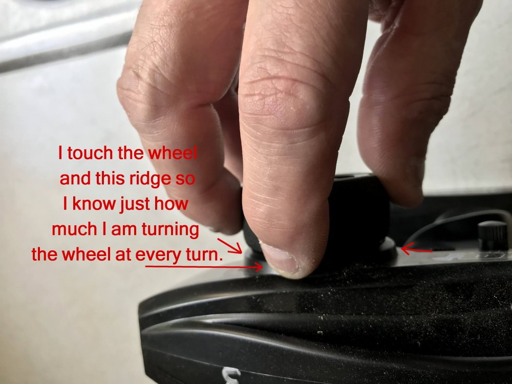
One helpful tip I tell new drivers (if the radio system allows it) is to place their fingers on the steering wheel but have one of them make contact with the transmitter case. Then you can get a feel for just how much you are really moving the steering wheel. Then use this information to
more control how much steering input you give in areas where they have trouble. It is amazing how that little tip has helped many new drivers. RC cars drive just like the big cars. The driver has to be smooth to be fast and weight shifting around is a really big deal in both size cars. The goal is to control it as much as the driver can.
OH YES, Here is today's test video of car #4. Enjoy!
 04-02-2023, 08:33 AM
#65
Thread Starter
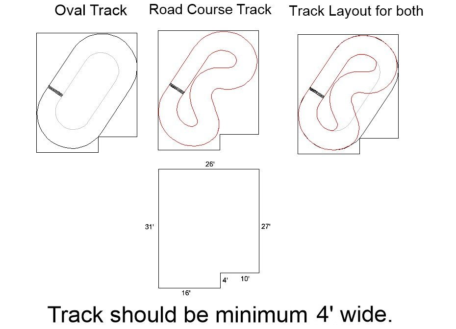
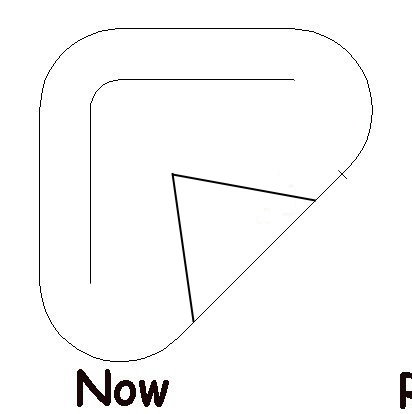
Any suggestions on that layout or maybe a better idea? I am open to suggestions at the moment.
The track is minimum 60" wide.
Last edited by testfly; 04-02-2023 at 08:36 AM.
 04-03-2023, 06:16 PM
#67
Thread Starter
This evening I marked out the new Road Course infield layout with masking tape. It worked out well with the track being set at 60" wide.
At this point I have removed all of the 3D printed inside wall sections so there is only masking tape marking the infield area. I plan to run some laps tomorrow and see how the Road Course flows.
I think it is going to be fine.
Yesterday I started setting up a car for the Road Course.
For a Road Course, one of the main things I focus on is braking. Getting a car that is running at high speed down a straight away then slowed down to make a 90 degree turn is pretty fun when you have the right amount of braking.
I also have to make sure the car is in the right area of the track at the end of the straightaway to make the tight turn. Get these two things right and the rest will follow. (Speed and Location) Get one of them wrong and the car is in the wall.
The third thing I focus on is throttle control. It can be real easy to over power the car in the slow sections on a Road Course. Just remember slower is almost always faster because the only speed that counts is when the car is moving toward the finish line.
The main thing to remember is setups do not work the same for everyone. What works for me may not work at all for others. The only reason I comment on my setups is to share what works for me and my thoughts behind them.
Doing so gives others things to think about when they are looking to improve lap times.
Road Course Laps Coming Soon!
 04-04-2023, 08:08 AM
#69
Thread Starter
04-05-2023, 04:00 AM
#70
Thread Starter
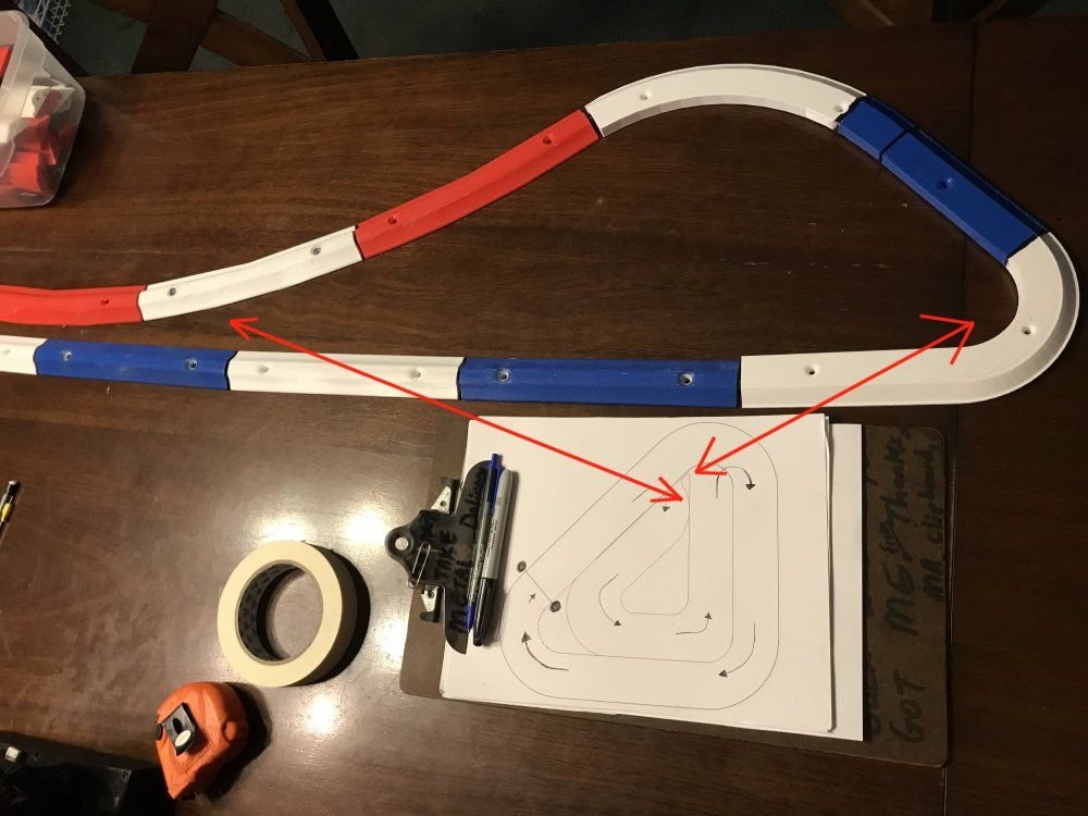
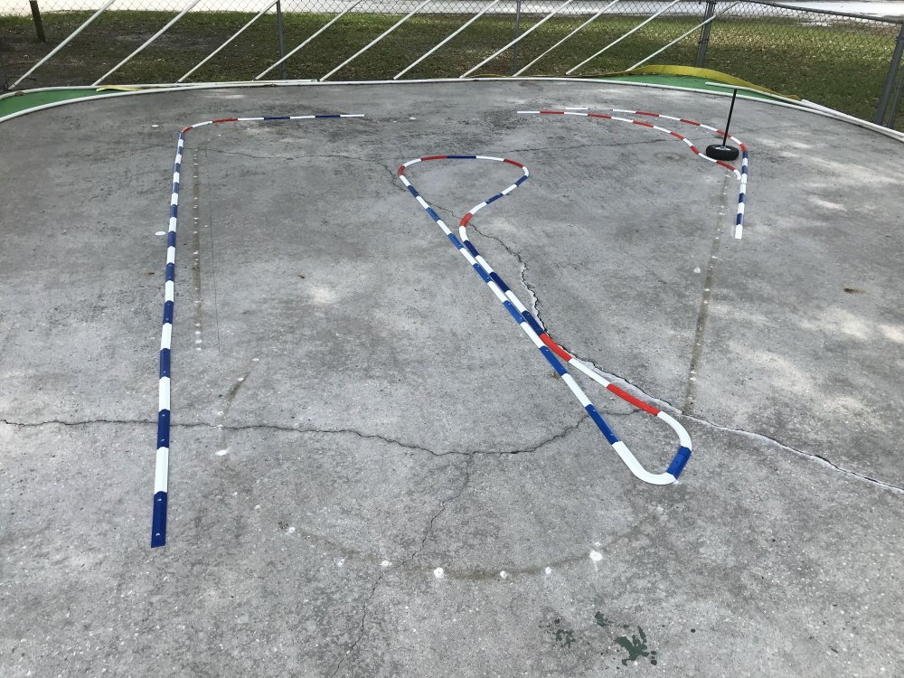
I have started printing the Infield Walls. Takes just over 8 hours to print 3 sections.
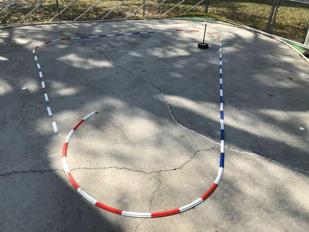
The Blue marks the straightaway.
Looks good to me so far.
I use a TPU ring at each joint to allow the material movement between the parts as they expand and contract with the weather.
So for now I just keep printing wall sections.
Note: The Oval will run counter clockwise and the Road Course will run clockwise.
 04-05-2023, 04:22 PM
#72
My new suggestion is the opposite of my simple suggestion - what if you hinged the yellow parts so that you could swing it open for oval and closed for road course. And if thats possible, maybe the left piece could be curved which would look good in either position.
Looking great, the whole project is really awesome.
Looking great, the whole project is really awesome.
04-06-2023, 11:35 AM
#73
Thread Starter
My new suggestion is the opposite of my simple suggestion - what if you hinged the yellow parts so that you could swing it open for oval and closed for road course. And if thats possible, maybe the left piece could be curved which would look good in either position.
Looking great, the whole project is really awesome.
Looking great, the whole project is really awesome.
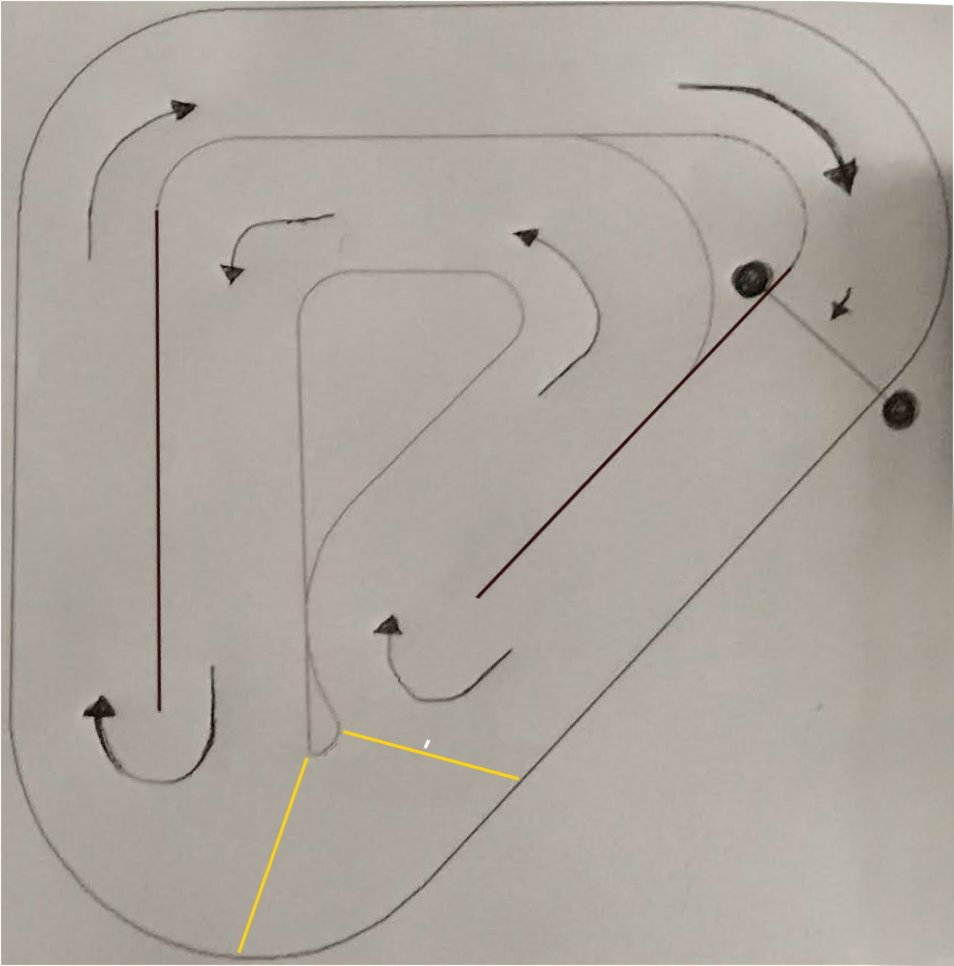
I have my printers working overtime at the moment printing wall sections and the custom sections. (see image) The tight curves came out great and the Road Course is looking real good. I will post updated images soon.
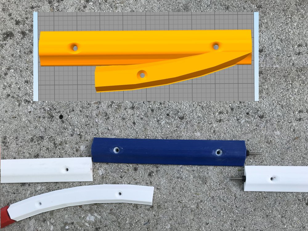
Here is one of the areas where two wall sections have to blend into one. So, I created a wall section to connect them together. I will be printing this one later today.
04-06-2023, 11:59 AM
#74
Thread Starter
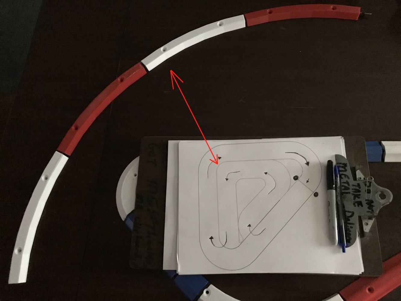
Here is a look at the Road Course as it comes together.
The track is a minimum of 60" in any area. The Oval was set at 72" so you can see where the walls were located before.
At 60" there is still a lot of racing area and it should be fun to drive.
It won't be long before I start screwing the wall sections in place.
I want to get all the wall sections printed and in place before I screw anything down. This way I can make changes if need be.