


1/18 chassis build need motor/gearing and tires for
 01-05-2023, 07:00 PM
#26

Thread Starter
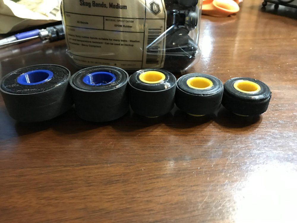
At this point I have designed a few more sizes of tire. It is clear I will need a better motor setup then what I have at the moment.
With a taller tire I need more gear ratio for sure. It might be a good idea to go brushless. The real issue is going to be ordering the right motor/esc.
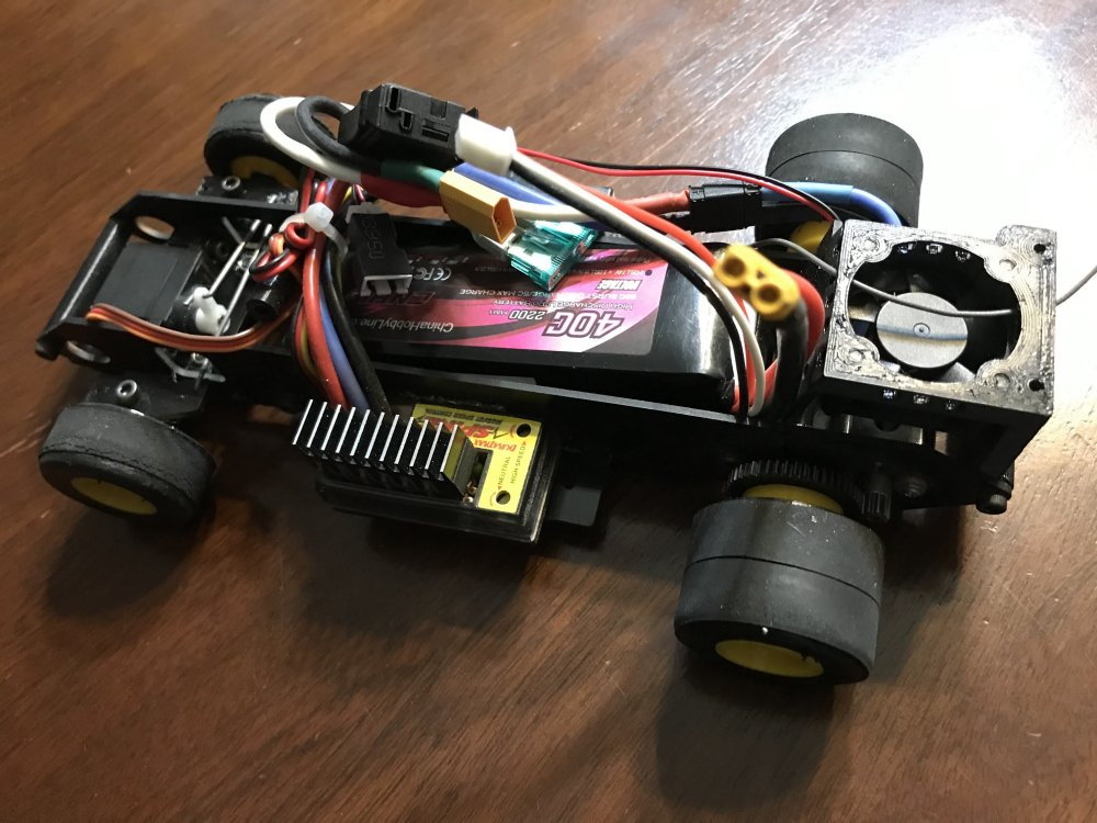
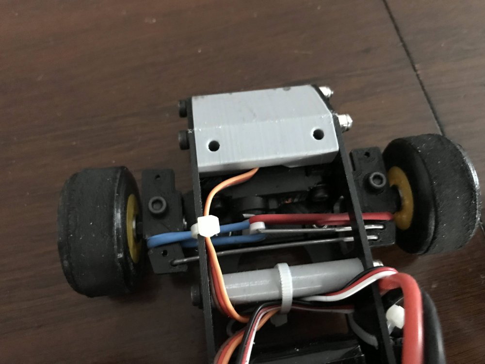
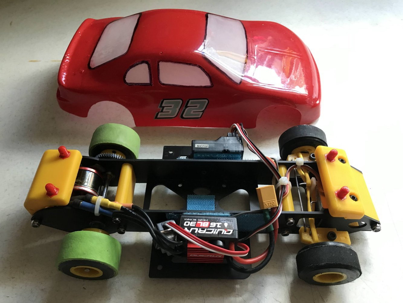
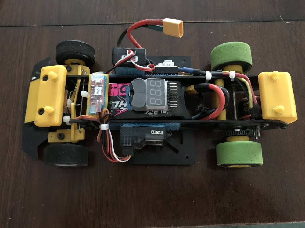
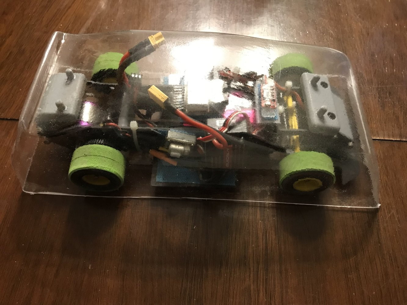
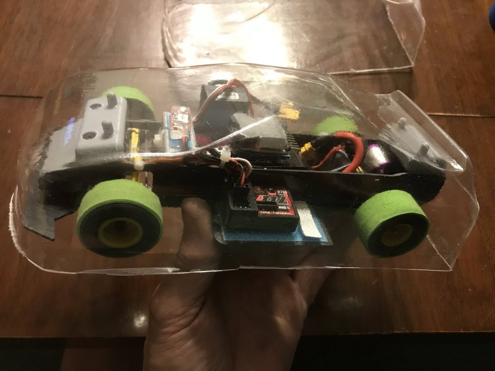
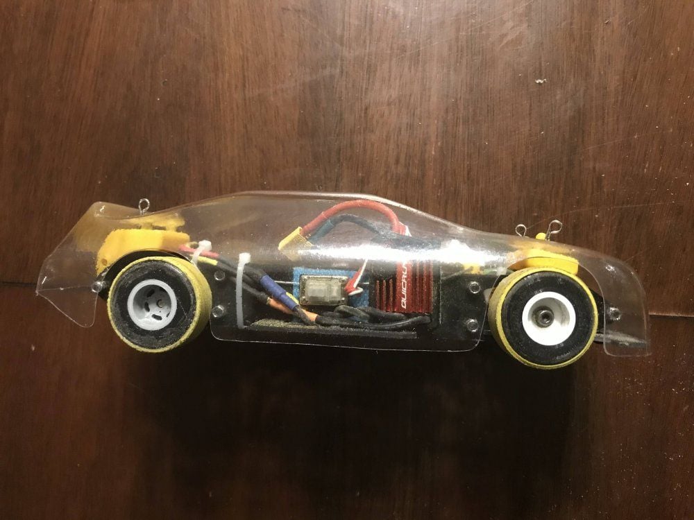
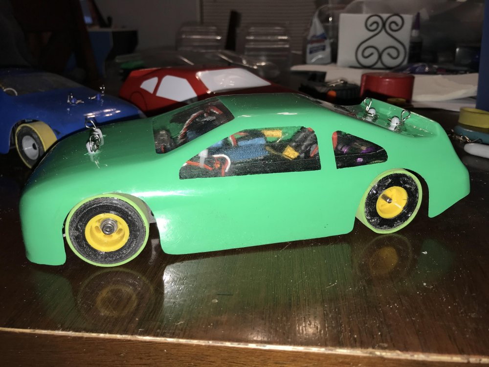
Here is a look at the chassis with the tires I have been testing. I am running 1 band on the front tires and 2 bands on the rear. I see Indy Car with those tires on it. I might just
have to come up with a Indy car as well. (when i get this one done of course)
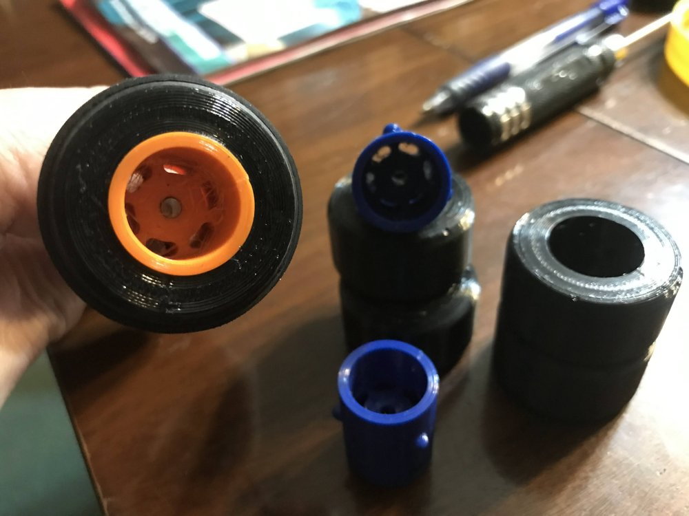
The capped tires are working really good on the concrete. I will get more tire test video as soon as I get bearings on the rear axle.
The axle size is .124" and I have ordered bearings 3 times and have yet to get a .125 ID bearing that will fit the axle properly.
So my goal now is to use a larger bearing and us a spacer to fit the axle to the bearings.
With a taller tire I need more gear ratio for sure. It might be a good idea to go brushless. The real issue is going to be ordering the right motor/esc.
Here is a look at the chassis with the tires I have been testing. I am running 1 band on the front tires and 2 bands on the rear. I see Indy Car with those tires on it. I might just
have to come up with a Indy car as well. (when i get this one done of course)
The capped tires are working really good on the concrete. I will get more tire test video as soon as I get bearings on the rear axle.
The axle size is .124" and I have ordered bearings 3 times and have yet to get a .125 ID bearing that will fit the axle properly.
So my goal now is to use a larger bearing and us a spacer to fit the axle to the bearings.
 01-08-2023, 11:07 PM
#27
Thread Starter
Well progress has been made in a few areas.
First with the axle bearings.
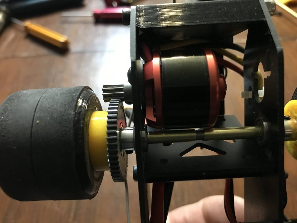
I used a larger bearing and a sleeve it to fit my axle.
Then the motor I was using was getting very hot so I went looking for another motor.

As it turns out I had some 3800kv motors so I bolted one of them in the car and used the ESC I had used on it in the passed.
It has a brake feature but it is either ON or OFF. So I turned the brake OFF. Mind you this motor and ESC are aircraft type but I had to start somewhere and really glad I did. From the test runs so far I am guessing I would need about a 1500KV motor for this project.
Since I am using a DX5R radio I have a lot I can do in the way of adjustments. So I set it up and have it running with no brake. (at the moment anyway)
I ran some hot laps today and made a few changes to the front end. Mainly to tighten it up. My first setup used Z bends which stress the holes when being installed and this can cause play in the steering.
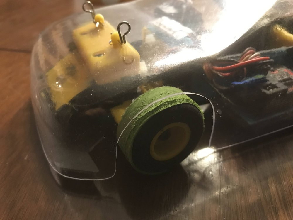
So, here comes one of my race secrets for you. The secrete is in the picture and it really does work if you set it up right.
First you will need a few balloons.

Cur the ends off of them where shown.
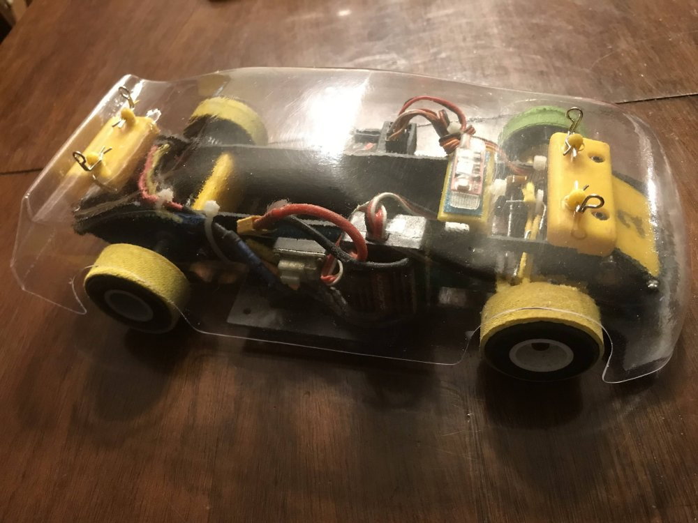
If you want to stick with Z bends then here is how I set them up. Notice that each spindle is being pulled into the servo horn. This means the spindles do not move around as the car is moving forward.
And then there is another way and here it is.
To keep from stressing the linkage holes I us only 90 degree bends. I also redesigned my spindles so they hold the balloon rubber and the material is thicker where the linkage connects to it.
Stay with me here because you might be amazed at how simple this system is and if you try it you may be even more amazed at how little play there is in the steering when it is done right.
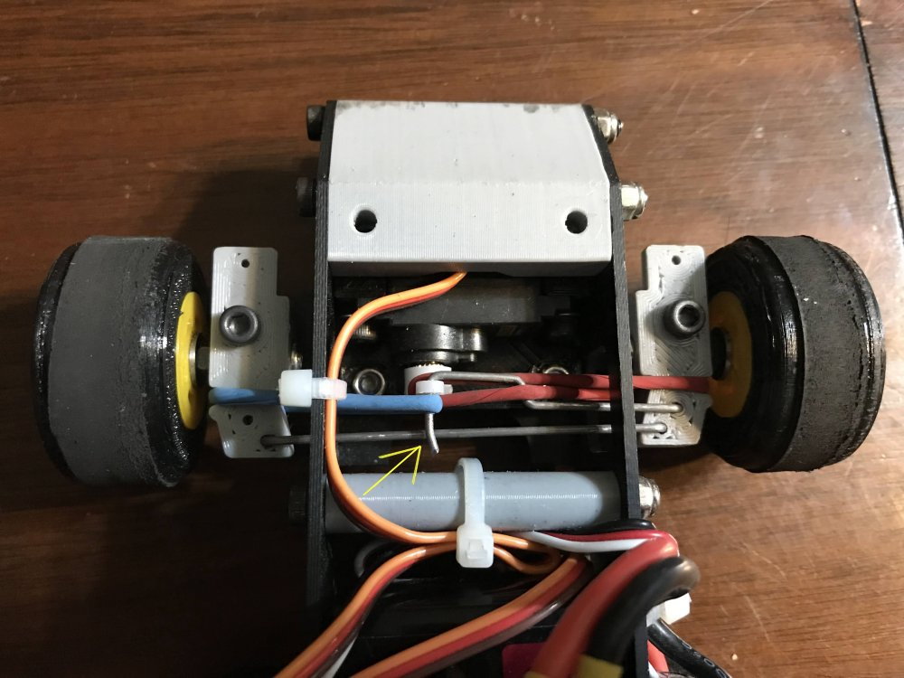
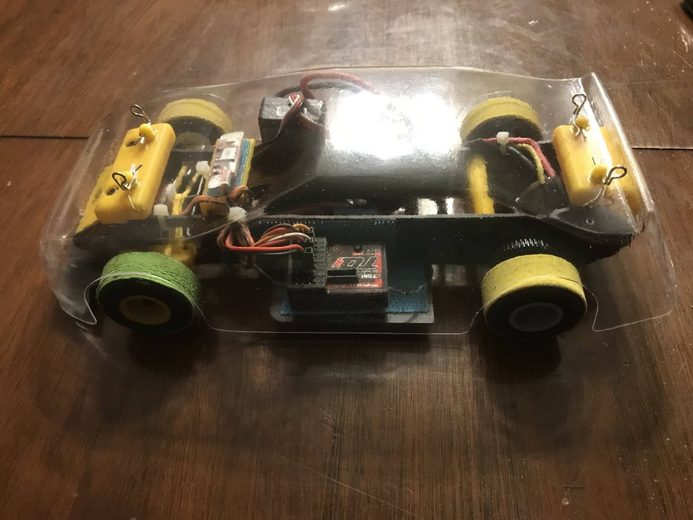
So here the system is installed. There is one Z bend and it is only to offset the servo linkage so it can be run straight over to the spindle. Notice how the balloon tips are installed.
Notice the red balloon end is just under the linkage wire and around the servo horn. Also notice the slight bend that can be seen in the wire that went through the servo horn.
This slight bend keeps the blue balloon end from sliding off the linkage. It also helps if the servo is placed so that the pressure on the balloon ends is always pulling them into the servo horn as shown here.
Notice the red balloon end and how it crosses over the Z bend in the servo linkage. This is what keeps the 90 degree bend from coming out of the spindle.
Notice how the chassis has a hole for the linkage to pass through. This hole is just tall enough for the linkage to go under but not so tall that it allows the 90 degree bends to lift out of the spindles.
As you can see it is a very simple setup and it gets rid of almost all the play in a linkage setup. Keep in mind that as a car rolls forward all the forces are pushing the back of each tire inward. Because
the balloon ends are pulling the rear of the tires inward already there is no play in the steering. Even on the bench you can feel a big difference in steering play once you install the balloon ends as shown here.
That is all I have at the moment.
First with the axle bearings.
I used a larger bearing and a sleeve it to fit my axle.
Then the motor I was using was getting very hot so I went looking for another motor.
As it turns out I had some 3800kv motors so I bolted one of them in the car and used the ESC I had used on it in the passed.
It has a brake feature but it is either ON or OFF. So I turned the brake OFF. Mind you this motor and ESC are aircraft type but I had to start somewhere and really glad I did. From the test runs so far I am guessing I would need about a 1500KV motor for this project.
Since I am using a DX5R radio I have a lot I can do in the way of adjustments. So I set it up and have it running with no brake. (at the moment anyway)
I ran some hot laps today and made a few changes to the front end. Mainly to tighten it up. My first setup used Z bends which stress the holes when being installed and this can cause play in the steering.
So, here comes one of my race secrets for you. The secrete is in the picture and it really does work if you set it up right.
First you will need a few balloons.
Cur the ends off of them where shown.
If you want to stick with Z bends then here is how I set them up. Notice that each spindle is being pulled into the servo horn. This means the spindles do not move around as the car is moving forward.
And then there is another way and here it is.
To keep from stressing the linkage holes I us only 90 degree bends. I also redesigned my spindles so they hold the balloon rubber and the material is thicker where the linkage connects to it.
Stay with me here because you might be amazed at how simple this system is and if you try it you may be even more amazed at how little play there is in the steering when it is done right.
So here the system is installed. There is one Z bend and it is only to offset the servo linkage so it can be run straight over to the spindle. Notice how the balloon tips are installed.
Notice the red balloon end is just under the linkage wire and around the servo horn. Also notice the slight bend that can be seen in the wire that went through the servo horn.
This slight bend keeps the blue balloon end from sliding off the linkage. It also helps if the servo is placed so that the pressure on the balloon ends is always pulling them into the servo horn as shown here.
Notice the red balloon end and how it crosses over the Z bend in the servo linkage. This is what keeps the 90 degree bend from coming out of the spindle.
Notice how the chassis has a hole for the linkage to pass through. This hole is just tall enough for the linkage to go under but not so tall that it allows the 90 degree bends to lift out of the spindles.
As you can see it is a very simple setup and it gets rid of almost all the play in a linkage setup. Keep in mind that as a car rolls forward all the forces are pushing the back of each tire inward. Because
the balloon ends are pulling the rear of the tires inward already there is no play in the steering. Even on the bench you can feel a big difference in steering play once you install the balloon ends as shown here.
That is all I have at the moment.
01-10-2023, 11:50 PM
#28
Thread Starter
Here is a look at how I made the body.
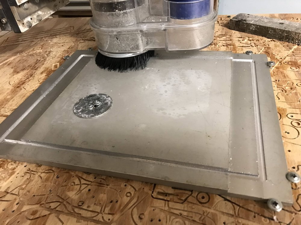
First I CNC cut 2 aluminum plates I had on hand to make a fixture that will hold the sheet plastic so it can be formed.
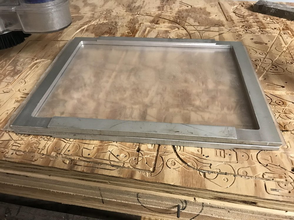
Here you can see both plates have been cut.
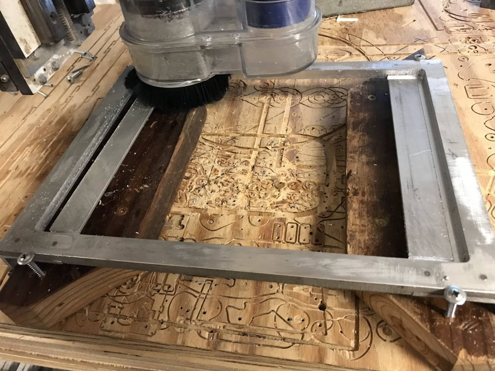
Then I added a handle on each end of one of the plates and then cut out the center.
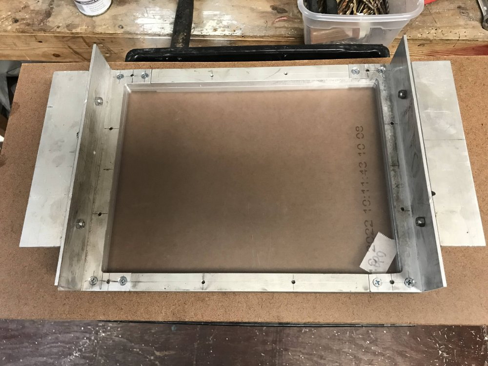
You guessed it. The plastic gets bolted between the 2 plates so it can be heated and formed.
It is not perfect but it will do just fine for a race car.
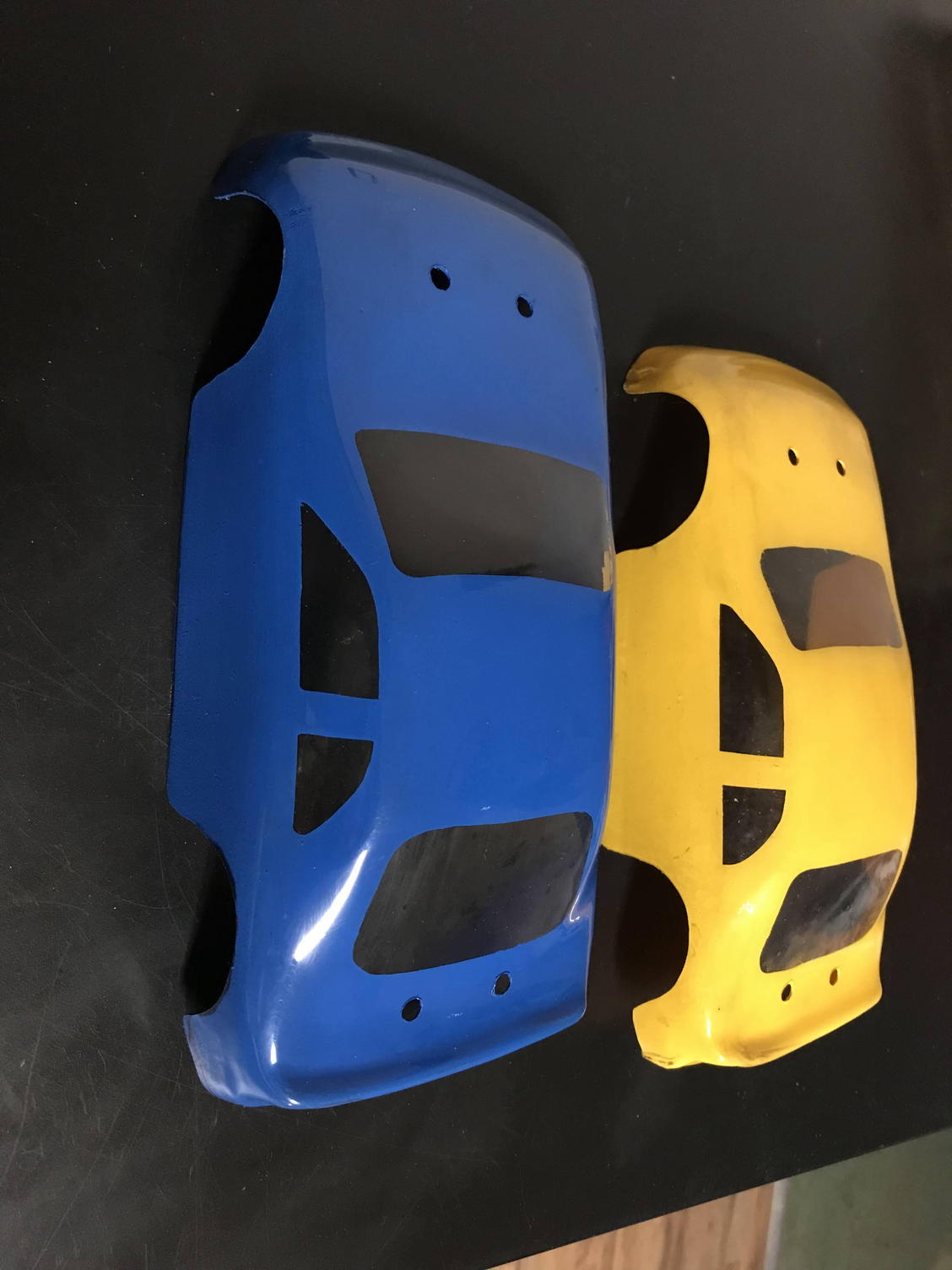
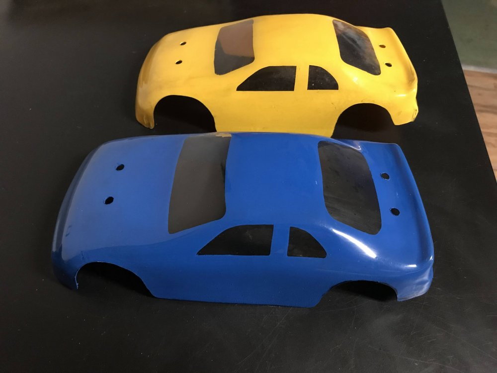
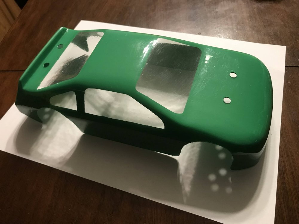
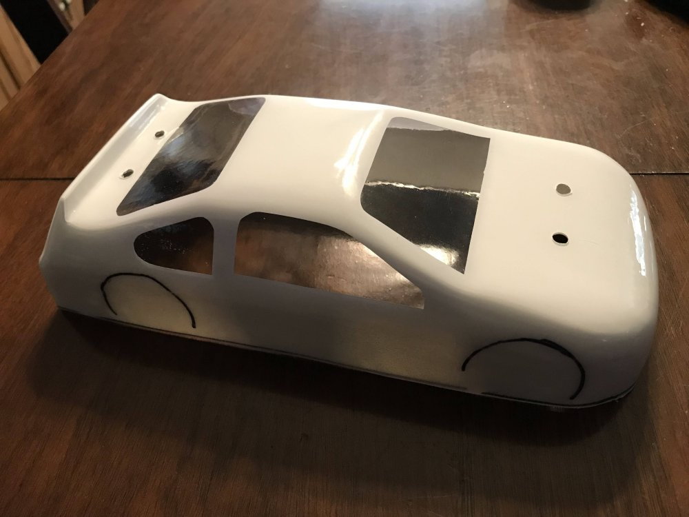
Here I added a little paint and marked out the windows.
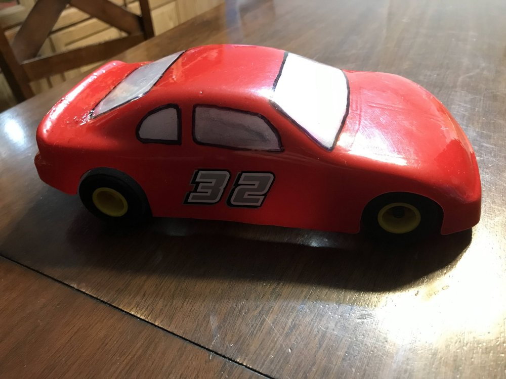
Then I added the car number.
Below are a few more body pictures.
The next step is to create the body mounts.
More details coming soon!
First I CNC cut 2 aluminum plates I had on hand to make a fixture that will hold the sheet plastic so it can be formed.
Here you can see both plates have been cut.
Then I added a handle on each end of one of the plates and then cut out the center.
You guessed it. The plastic gets bolted between the 2 plates so it can be heated and formed.
It is not perfect but it will do just fine for a race car.
Here I added a little paint and marked out the windows.
Then I added the car number.
Below are a few more body pictures.
The next step is to create the body mounts.
More details coming soon!
01-13-2023, 08:45 AM
#29
Thread Starter
Things are moving right along.
Here is information about how I designed the body mounts.
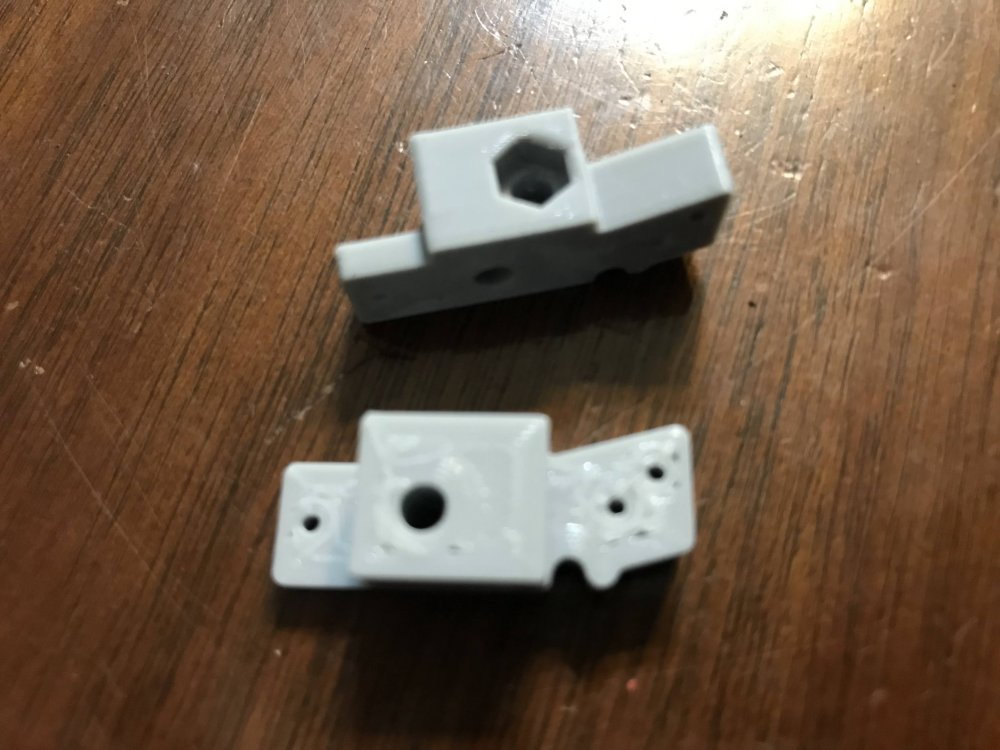
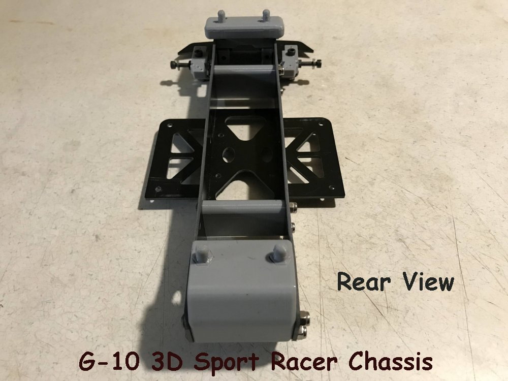
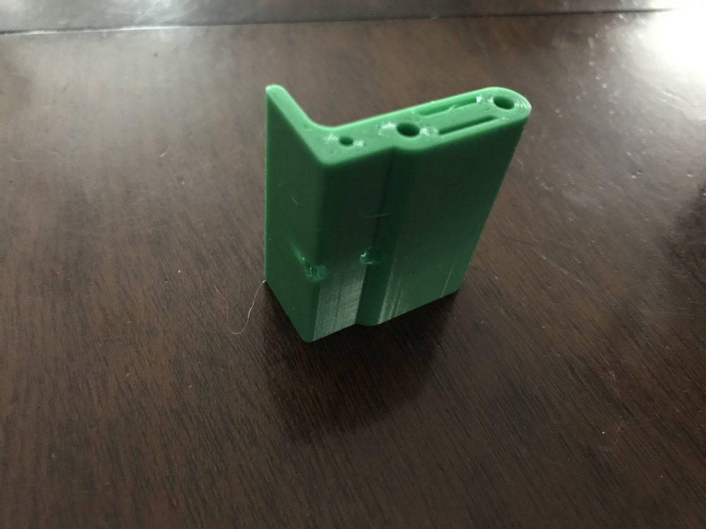
Here is a look at the rear body mount. I need to make a change to the rear of the chassis rails but the mounts are perfect.
Rear body mount.
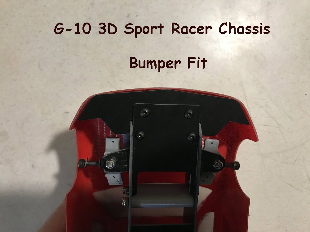
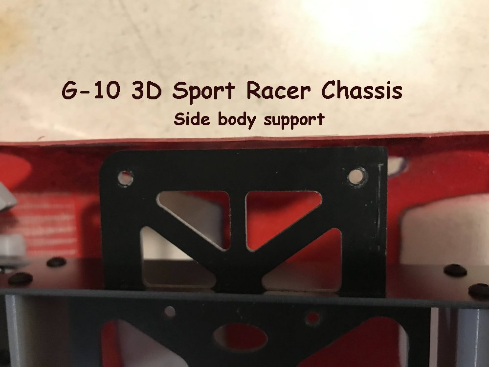
Here is a look at the front body mount.
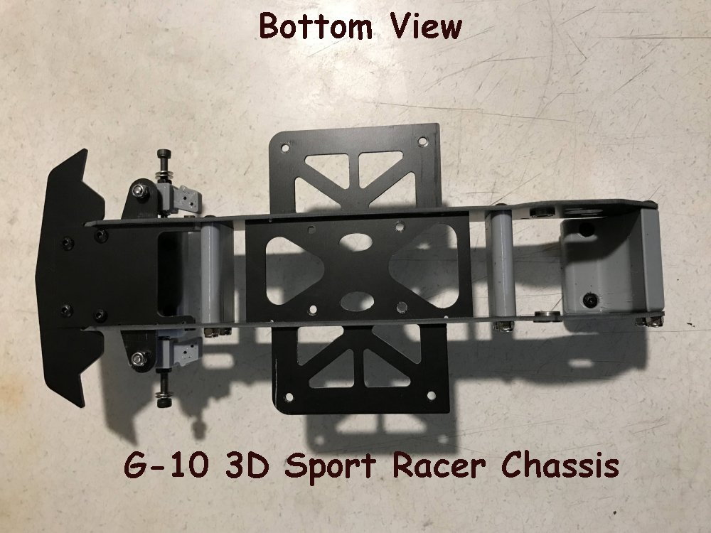
Look close... The body post are replaceable.
Here I replaced the yellow body post to red ones to closer match the red body.
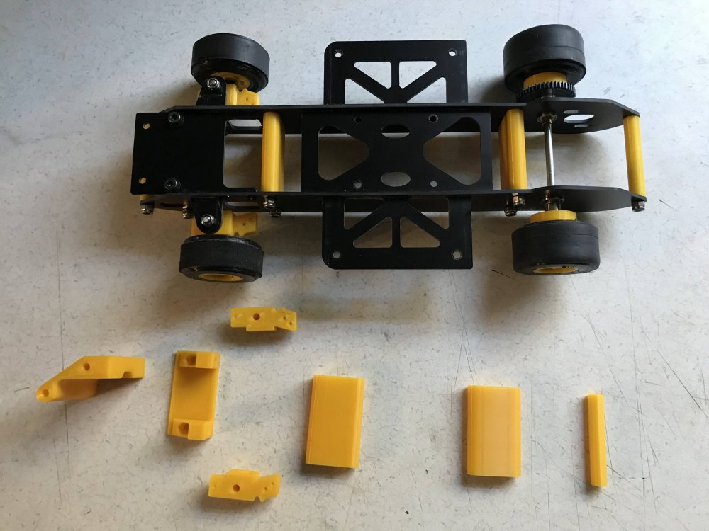
NOTE: This image is showing the bottom side of the chassis.
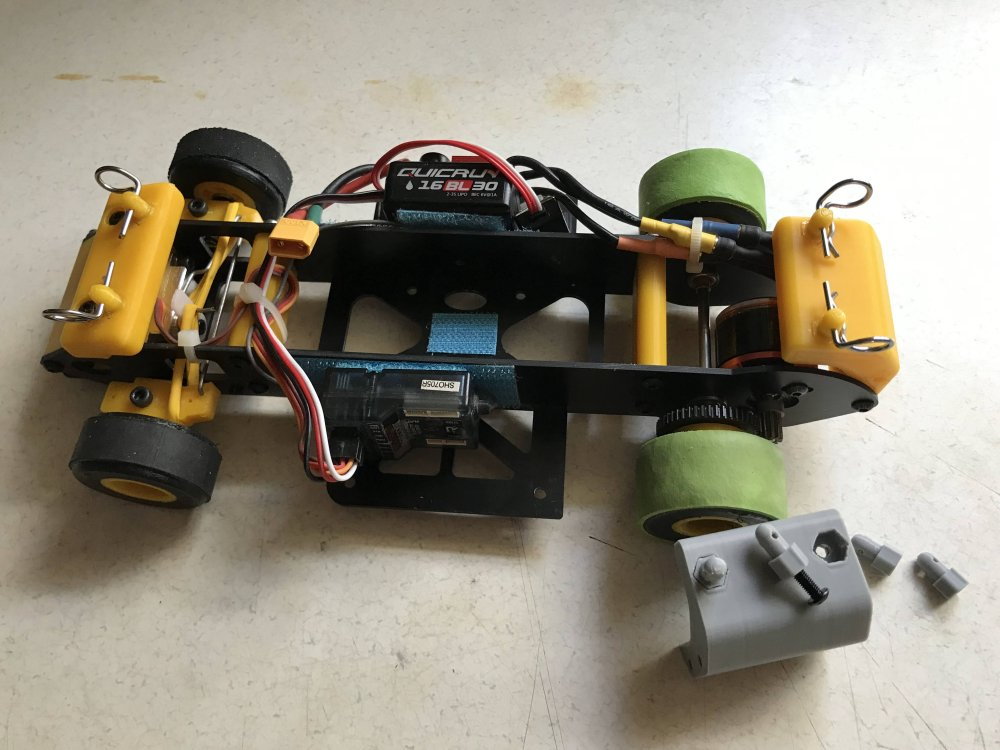
Here is a image of the latest chassis and some of the 3D printed chassis parts. I am still making changes but it is coming right along.
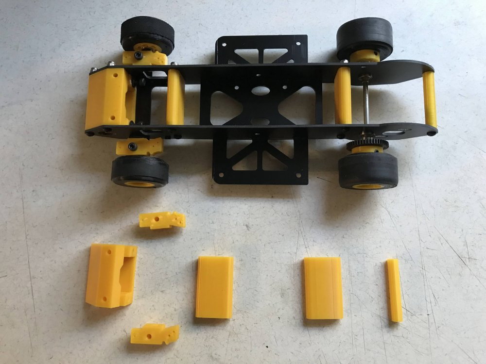
Top view of the chassis.
More info coming soon.
Here is information about how I designed the body mounts.
Here is a look at the rear body mount. I need to make a change to the rear of the chassis rails but the mounts are perfect.
Rear body mount.
Here is a look at the front body mount.
Look close... The body post are replaceable.
Here I replaced the yellow body post to red ones to closer match the red body.
NOTE: This image is showing the bottom side of the chassis.
Here is a image of the latest chassis and some of the 3D printed chassis parts. I am still making changes but it is coming right along.
Top view of the chassis.
More info coming soon.
Last edited by testfly; 01-13-2023 at 08:50 AM.
01-13-2023, 04:52 PM
#30
Thread Starter
The body has been mounted and the project is almost complete.
Only a few more things need to be completed and then I will start printing my race team and wait for my grand kids to come to grandpa's house cause that is where the racing will be.
For now here are a few more pictures.
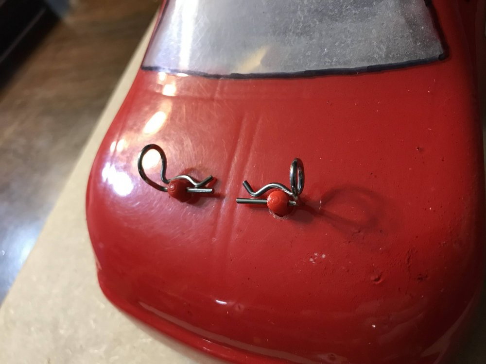
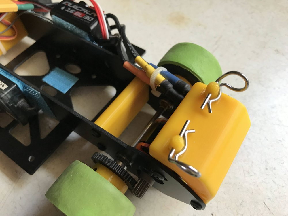
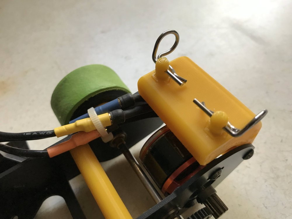
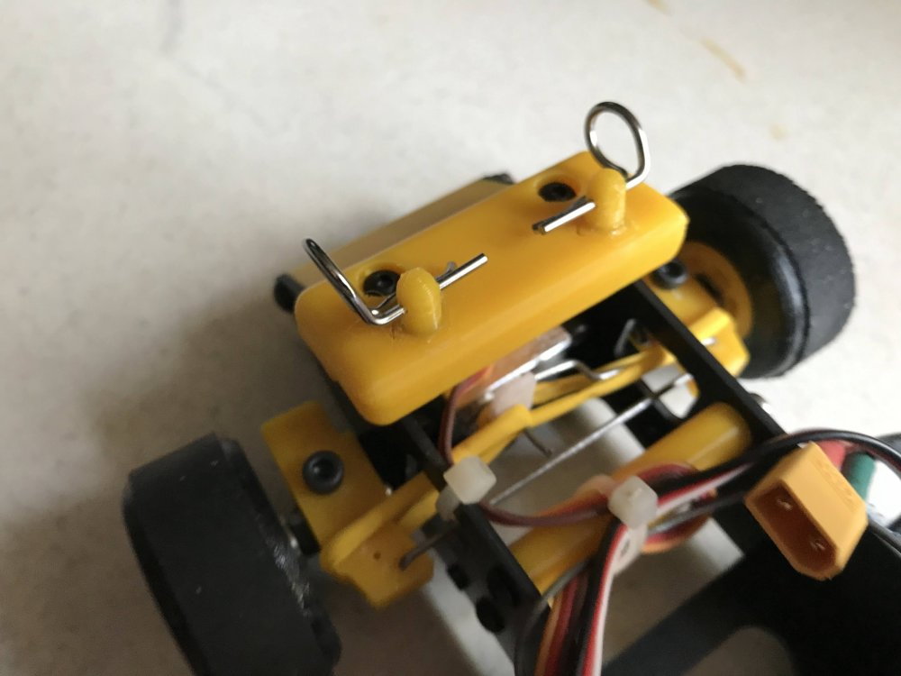
Hood pins.

Deck lid pins.
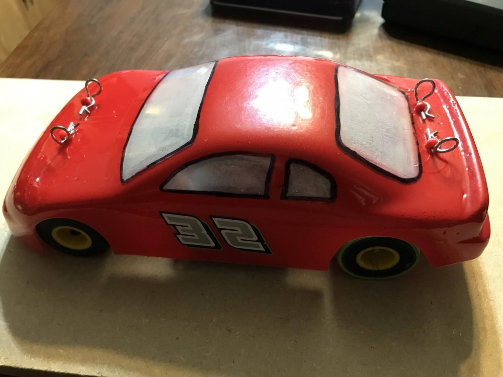
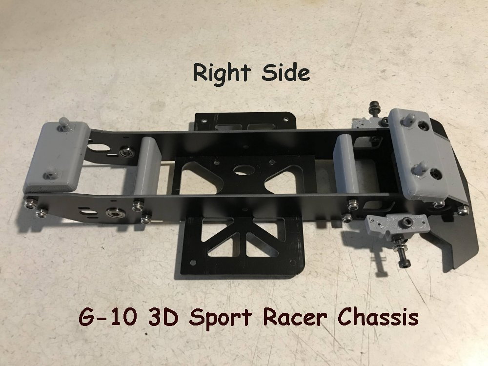
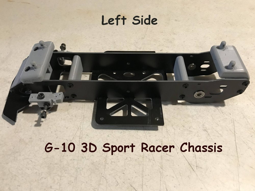
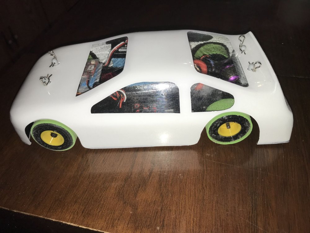
Left side
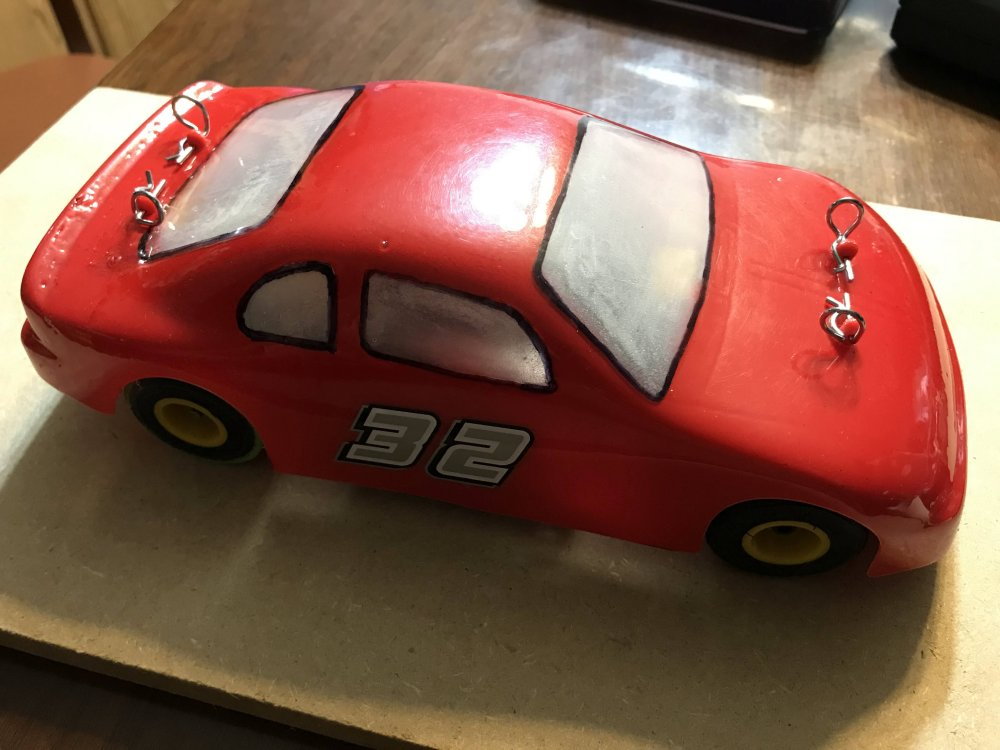
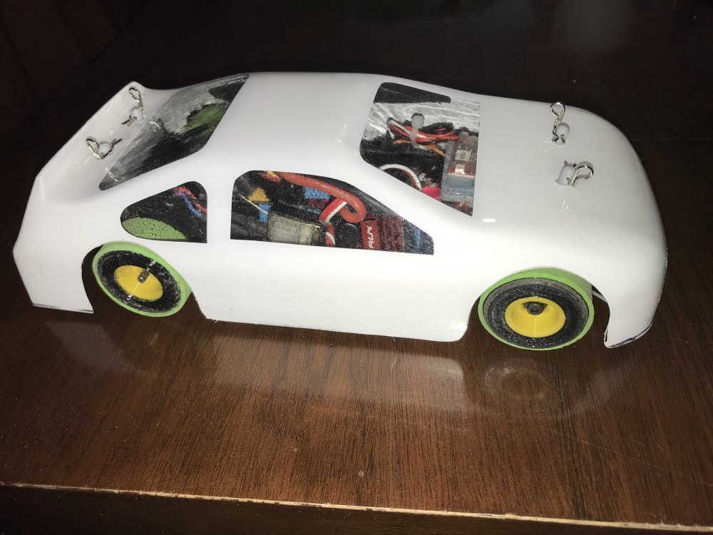
Right side
If you have any questions or want to know how I designed any part of the car or how it was created just ask.
I am happy to share the information when the car is done.
Only a few more things need to be completed and then I will start printing my race team and wait for my grand kids to come to grandpa's house cause that is where the racing will be.
For now here are a few more pictures.
Hood pins.
Deck lid pins.
Left side
Right side
If you have any questions or want to know how I designed any part of the car or how it was created just ask.
I am happy to share the information when the car is done.
 01-13-2023, 09:47 PM
#32
Thread Starter
The 3D printed body post seam to be working really well. The good news is they are easy to print and simple to replace if need be.
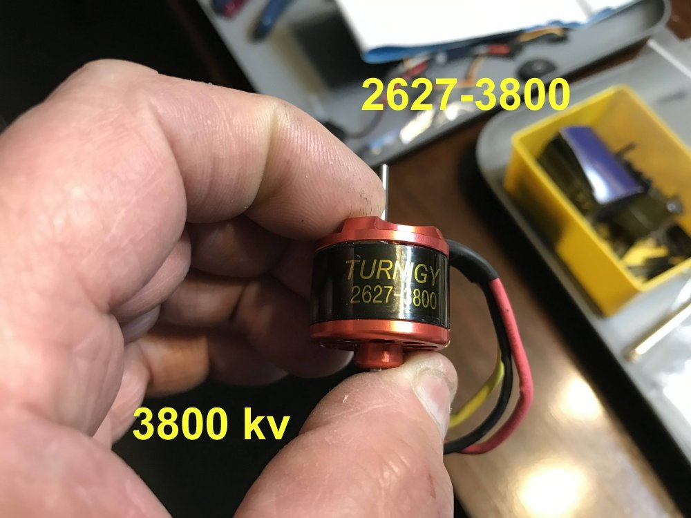
The motor is a out runner motor using a 9 tooth pinion and a 48 tooth spur gear (48 pitch gears)

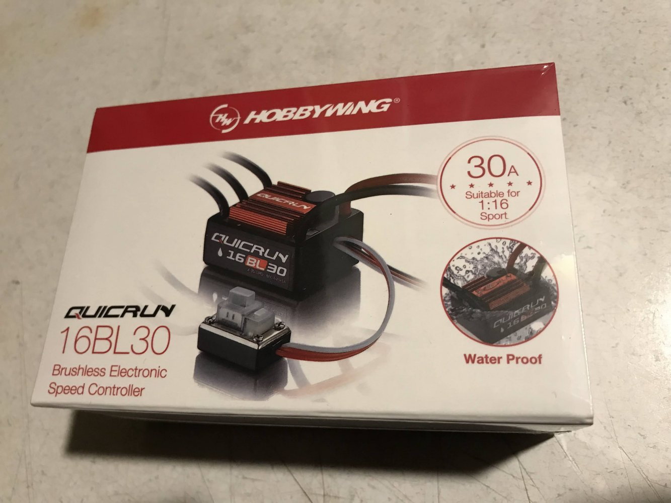
Here is a look at the ESC.
01-13-2023, 09:56 PM
#33
Thread Starter
This car is a blast to drive. I do have the throttle cut back to 60% and it is running and driving really well with no setup. (I bolted it together, installed the electronics and put on the body)
The video is short but you get the idea. If you want details of something I did not cover in this thread just ask. I am happy to share what I have designed and built with anyone interested.
The video is short but you get the idea. If you want details of something I did not cover in this thread just ask. I am happy to share what I have designed and built with anyone interested.
01-15-2023, 09:41 PM
#34
Thread Starter
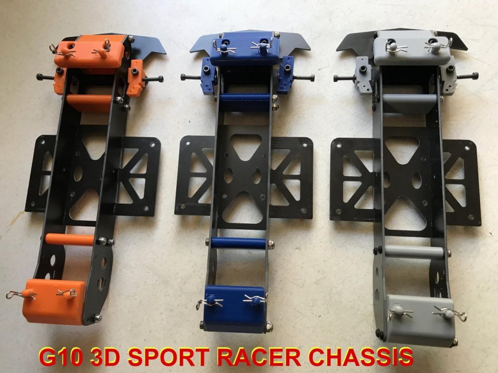
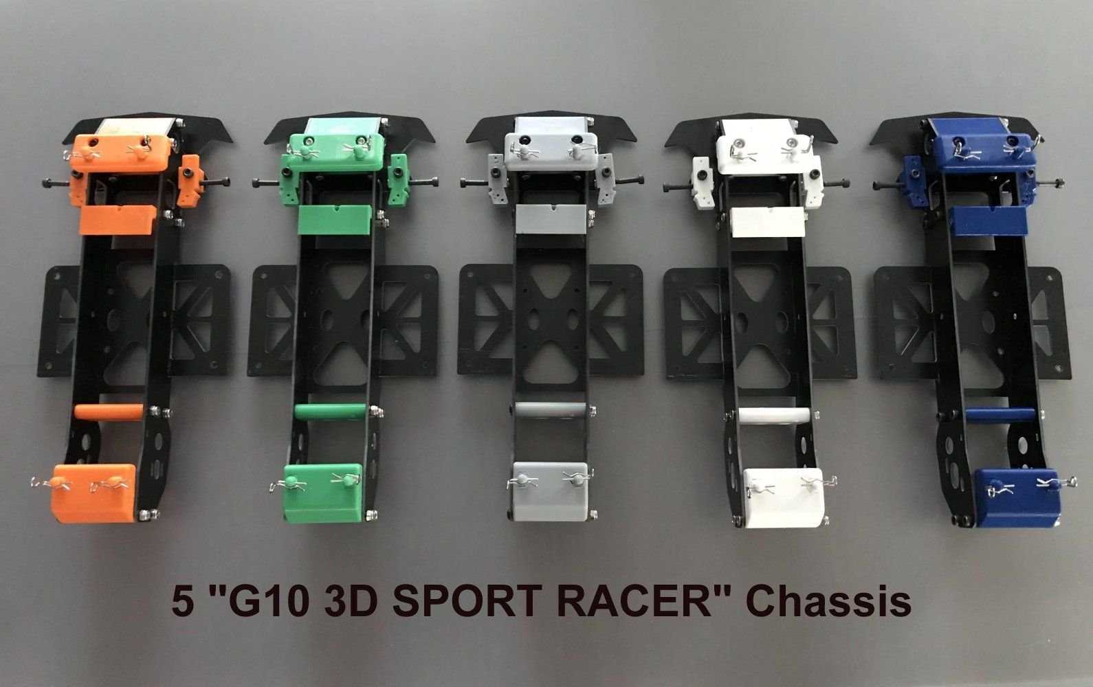
Here are some pictures of the final design of the car I have created. It shall be know as the "G-10 3D Sport Racer". AKA "G10 3D SR"
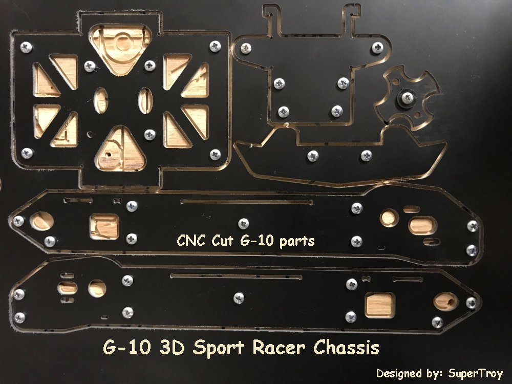
The G-10 parts are cut from .062 G-10 FR4 material using a .0625 bit at 15,000 rpm and 15 ipm.
The Chassis bolts together using 3mm hardware. All nuts are nylon lock nuts.
Note the body post are replaceable. They can be printed to match the car color.
Rear axle bearing OD is 9mm. (The size of the bearing hole cut in the chassis) I use a 3x7x3 for the front wheels. (All bearings are flanged bearings)
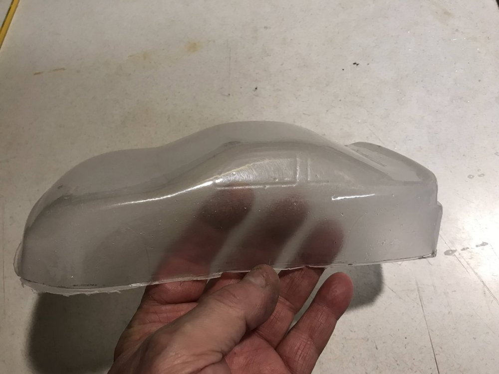
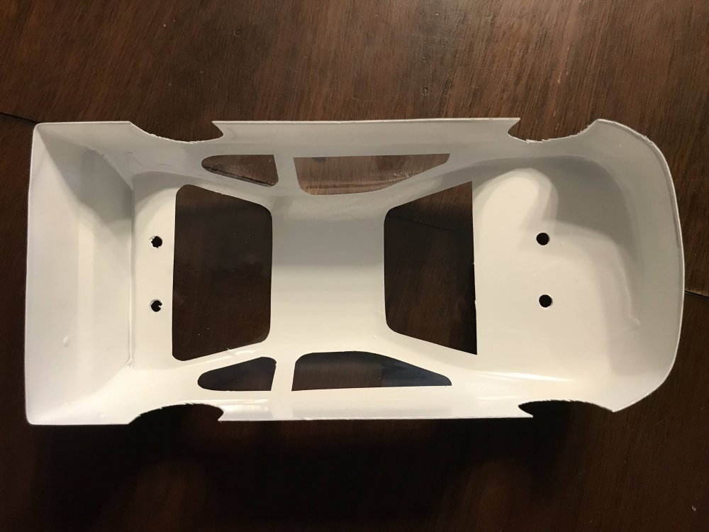
The body was formed from .062 PETG plastic. This makes the body strong. Note the thickness at the body edge.
Note the body thickness at the edge.
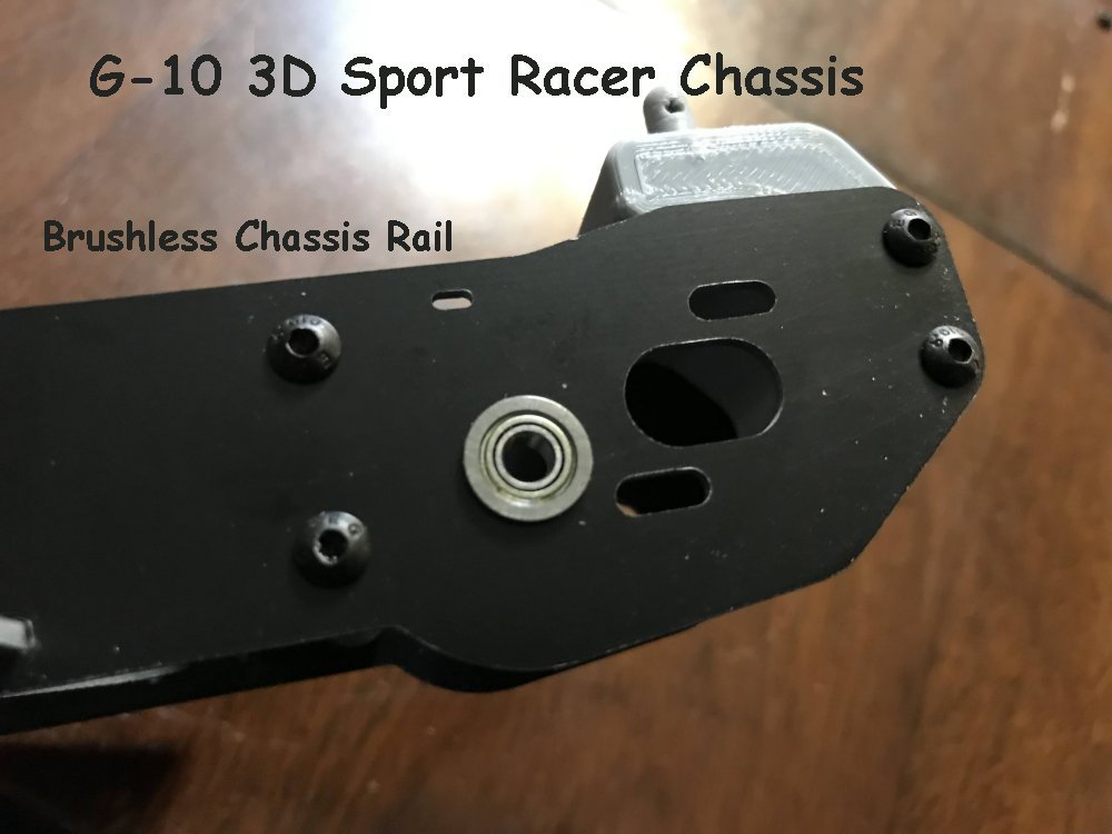
The chassis is designed to run brushless or a slot car motor.
Mount this rail on the left side as shown if you want to run a brushless motor setup.
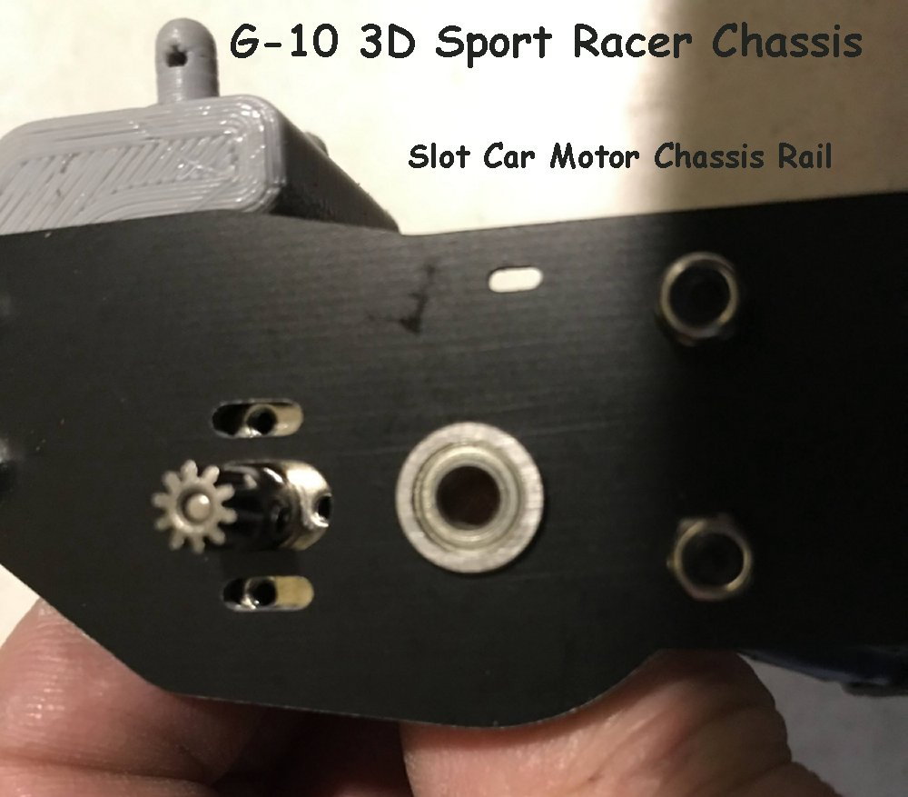
Here is a look at the slot car motor bolt pattern. If you want to run a slot car motor, place this chassis rail on the left side of the car.
That is about it on the G10 parts.
More information on the 3D printed parts coming soon!
The G-10 parts are cut from .062 G-10 FR4 material using a .0625 bit at 15,000 rpm and 15 ipm.
The Chassis bolts together using 3mm hardware. All nuts are nylon lock nuts.
Note the body post are replaceable. They can be printed to match the car color.
Rear axle bearing OD is 9mm. (The size of the bearing hole cut in the chassis) I use a 3x7x3 for the front wheels. (All bearings are flanged bearings)
The body was formed from .062 PETG plastic. This makes the body strong. Note the thickness at the body edge.
Note the body thickness at the edge.
The chassis is designed to run brushless or a slot car motor.
Mount this rail on the left side as shown if you want to run a brushless motor setup.
Here is a look at the slot car motor bolt pattern. If you want to run a slot car motor, place this chassis rail on the left side of the car.
That is about it on the G10 parts.
More information on the 3D printed parts coming soon!
01-15-2023, 09:58 PM
#35
Thread Starter
The car is coming along great.
My next build will be a Sprint Car version so I need a 2 in 1 track design. 1) being an oval track and 2) being a road course option as shown in my design.
I would like the track to have a good flow to it. If you have an idea for a track layout that will fit my concrete area I would enjoy seeing it. It don't have to be a fancy drawing either. Sketch it out
and I will make the fancy drawing of it if need be.
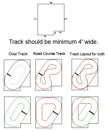
I have drawn up another track layout with this set being a 6' wide track.
I have a lap counting system on the way so I need the Start/Finish line on the right side of the concrete layout as shown in the second row of track layouts.
 01-18-2023, 01:49 AM
#38
Thread Starter
Now a little information about making your own RC bodies. (Here is how I do it)
Here you can see that the plug failed across the hood. It Happens!
After you have your plug made then you make the body from it. (I will be making a wood plug for this project. More on this later.
For now I will show the steps I take to form the body.
It helps to have the proper tools. But you can use what you have. One tip though. As you will see you do not need a bunch of holes in your vacuum top. One large hole is more than enough if you use a BUCK
under your plug and elevate it. If you want more information on this just ask and I will cover it. Trust me it is not as hard as you might think.

I made a fixture to hold the PETG while it is being formed.
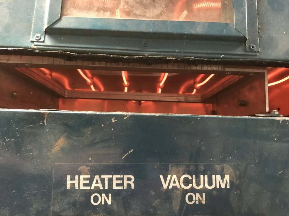
Notice there is only one hole in my vacuum forming machine.
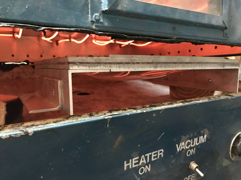
Here is a look as the PETG is heating up.
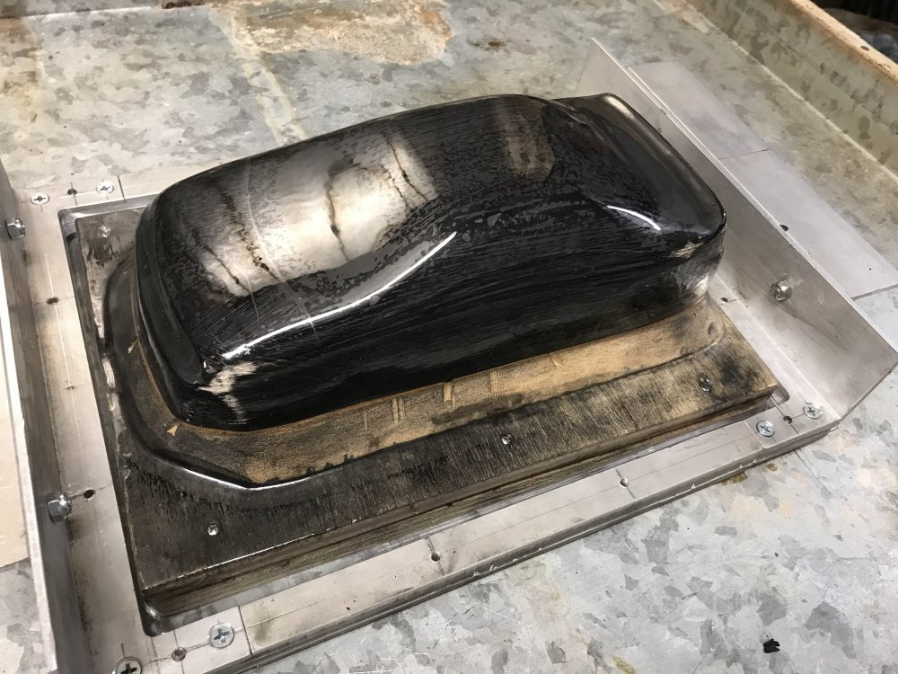
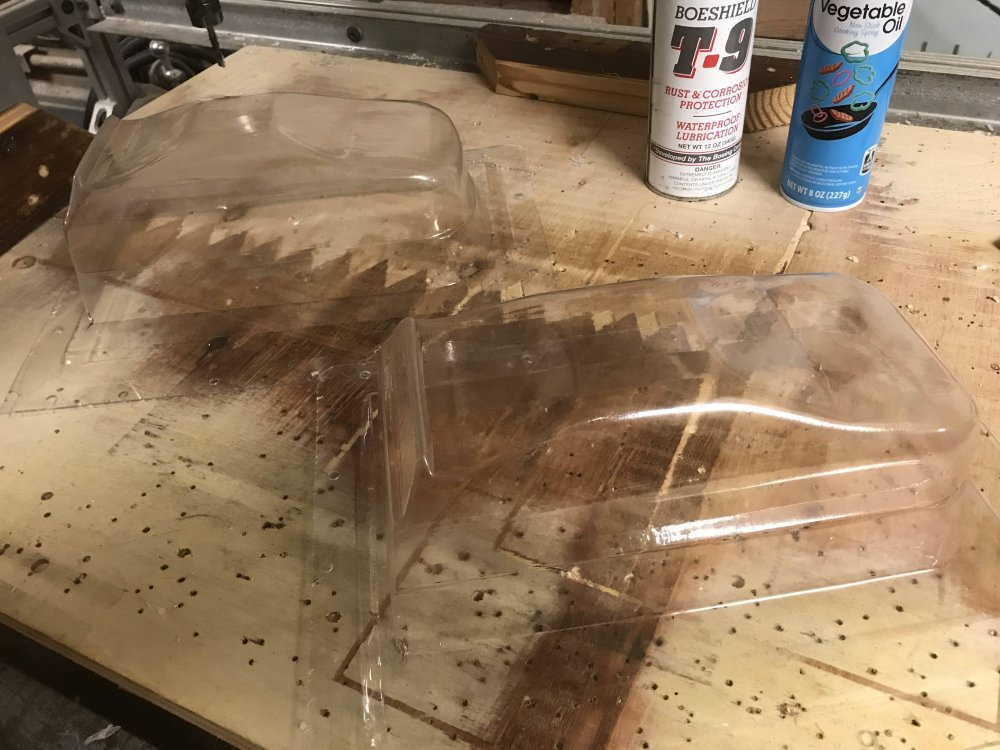
When the material is ready I place the plug over the hole, hit the vacuum switch, flip the fixture and place it over the plug and push it down. Notice how the single hole does
a great job of pulling the material to the plug. I should note that I coat the plug with cooking spray before I pull the part. That is what you are seeing under the PETG. A good
washing before painting removes the spray.
The body is cut from the sheet and given a quick wash with soap and water. Then it is marked for cutting.
I do a rough cut then finish with a Dremel tool using a sanding drum.
Then I fit the body to the Chassis.
Here is a look at how I covered the windows while painting the body. I created all the windows in CAD and then ran a sheet of vinyl upside down through my printer and printed the window
layouts on the back side.
I marked the window locations and then added the vinyl cutouts on the inside of the body.
Then I removed the layout tape and covered the body post holes with tape.
With the body taped so I can hold it the paint is sprayed on.
I spray a few light coats and check for any areas I missed.
Before the paint dries I remove the tape and the window vinyl and here is a look at the results.
I let the paint dry over night and then I clean up any over spray with acetone.
It may not be the right way, but that is how I do it and the results are worth the effort for sure.
If you have any questions or want more information on any part of this project just ask. I am always willing to help when I can.
Here you can see that the plug failed across the hood. It Happens!
After you have your plug made then you make the body from it. (I will be making a wood plug for this project. More on this later.
For now I will show the steps I take to form the body.
It helps to have the proper tools. But you can use what you have. One tip though. As you will see you do not need a bunch of holes in your vacuum top. One large hole is more than enough if you use a BUCK
under your plug and elevate it. If you want more information on this just ask and I will cover it. Trust me it is not as hard as you might think.
I made a fixture to hold the PETG while it is being formed.
Notice there is only one hole in my vacuum forming machine.
Here is a look as the PETG is heating up.
When the material is ready I place the plug over the hole, hit the vacuum switch, flip the fixture and place it over the plug and push it down. Notice how the single hole does
a great job of pulling the material to the plug. I should note that I coat the plug with cooking spray before I pull the part. That is what you are seeing under the PETG. A good
washing before painting removes the spray.
The body is cut from the sheet and given a quick wash with soap and water. Then it is marked for cutting.
I do a rough cut then finish with a Dremel tool using a sanding drum.
Then I fit the body to the Chassis.
Here is a look at how I covered the windows while painting the body. I created all the windows in CAD and then ran a sheet of vinyl upside down through my printer and printed the window
layouts on the back side.
I marked the window locations and then added the vinyl cutouts on the inside of the body.
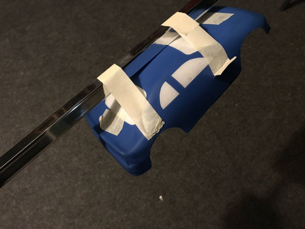
Then I removed the layout tape and covered the body post holes with tape.
With the body taped so I can hold it the paint is sprayed on.
I spray a few light coats and check for any areas I missed.
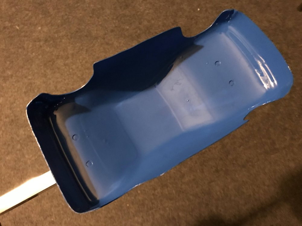
Before the paint dries I remove the tape and the window vinyl and here is a look at the results.
I let the paint dry over night and then I clean up any over spray with acetone.
It may not be the right way, but that is how I do it and the results are worth the effort for sure.
If you have any questions or want more information on any part of this project just ask. I am always willing to help when I can.
01-18-2023, 08:45 AM
#39
Thread Starter
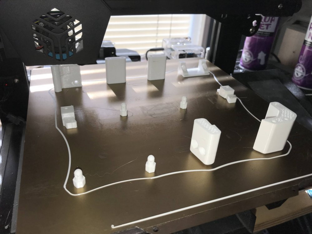
Here is a look at all the Chassis parts as they are printed at one time.
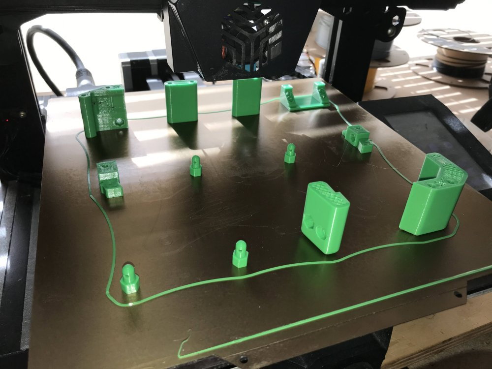
The parts are printed from PETG at 40% infill. They were designed and laid out so no support is needed.
Printing the parts all at once takes almost 12 hours. There is 3 hours to go in each of the prints pictured above.
01-19-2023, 12:21 PM
#40
Thread Starter
I have updated the chassis to include a place to mount a transponder. The 12 in 1 stl parts file has been updated to include the transponder mount.
Here is a look at the chassis after the transponder mount was added.
01-24-2023, 10:14 PM
#42
Thread Starter
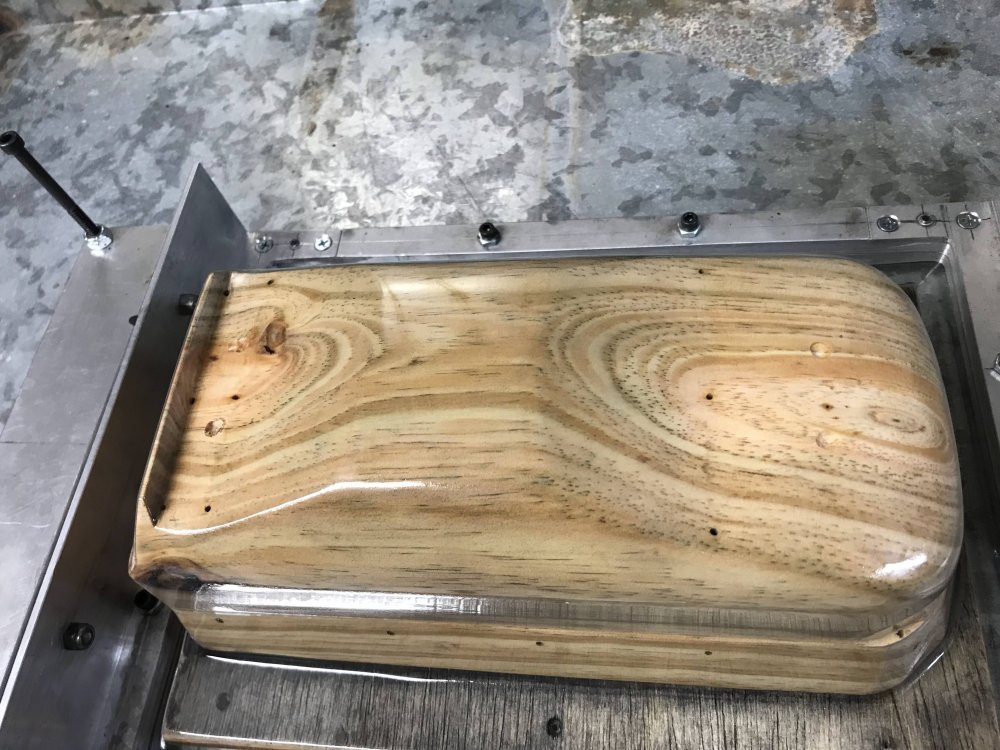
The time has come to build a wood plug.
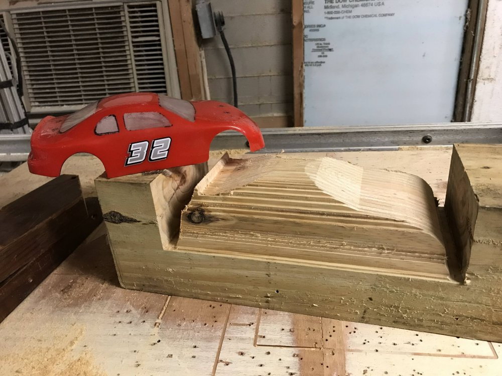
I will create a simple 3D drawing of the plug and cut it from a solid block of wood. (a 6X6 cut 16" long)
Here is a look at how I do it....
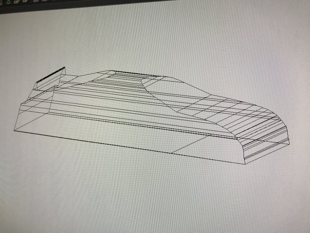
First I draw a side view of the body I want to make and then I draw a view of the rear. I then put those in my CAD program.
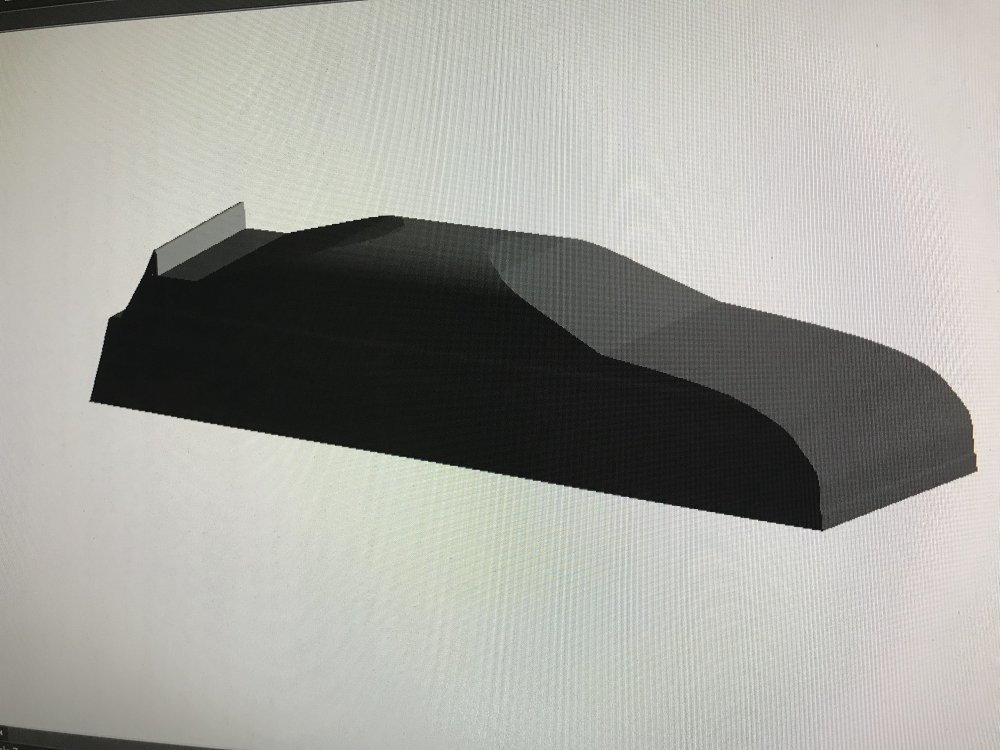
Then I create a solid shape using the two views. I also add a bottom to the drawing which helps make using the plug very easy. (more on this later)
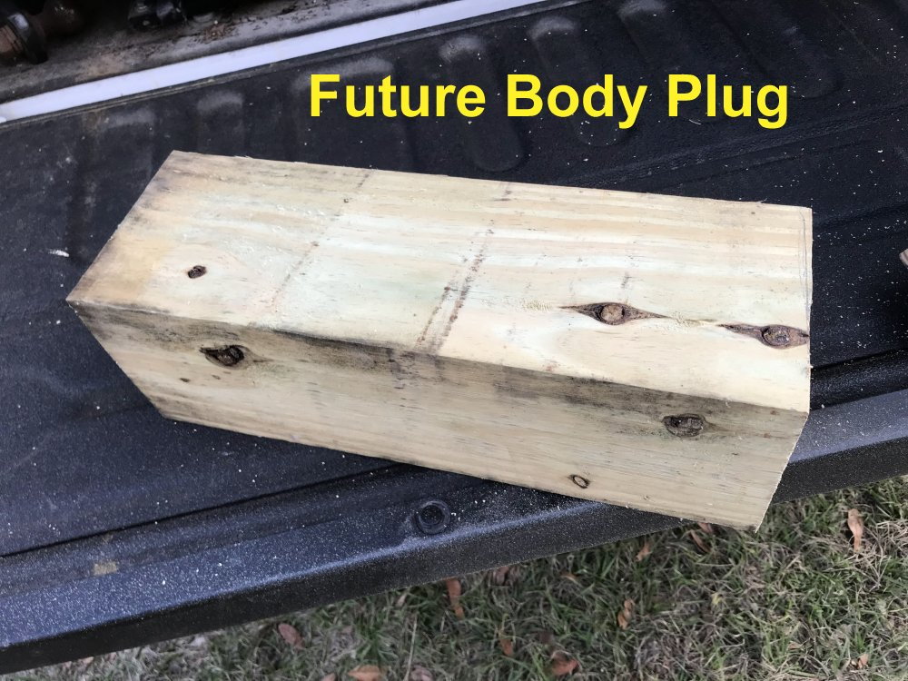
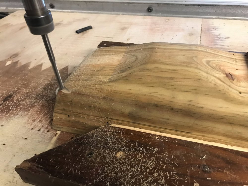
I cut the 6X6 to 16" long.
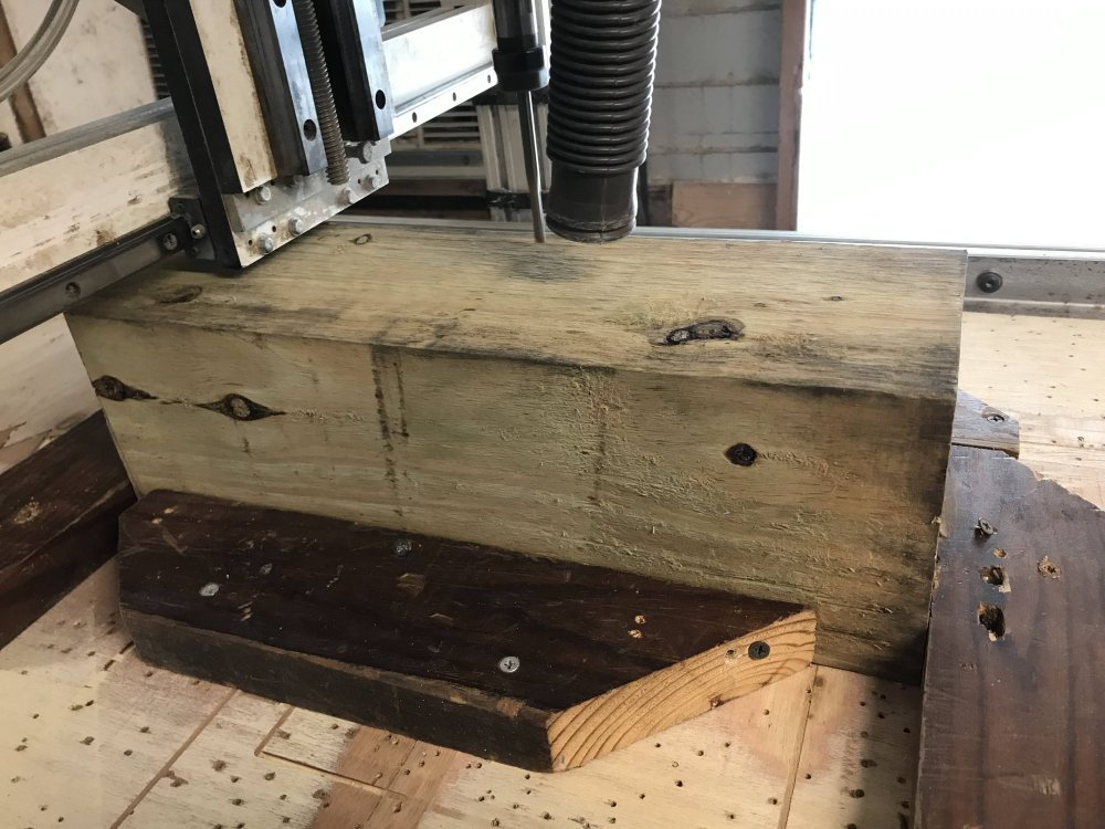
Then I attach the 6X6 to the cnc machine for cutting. You could also draw your profile on the side and back of the block and carve it by hand if you do not have a cnc machine that will do the job.
As you will see, I had no issue cutting the 6X6 block to shape on my machine.
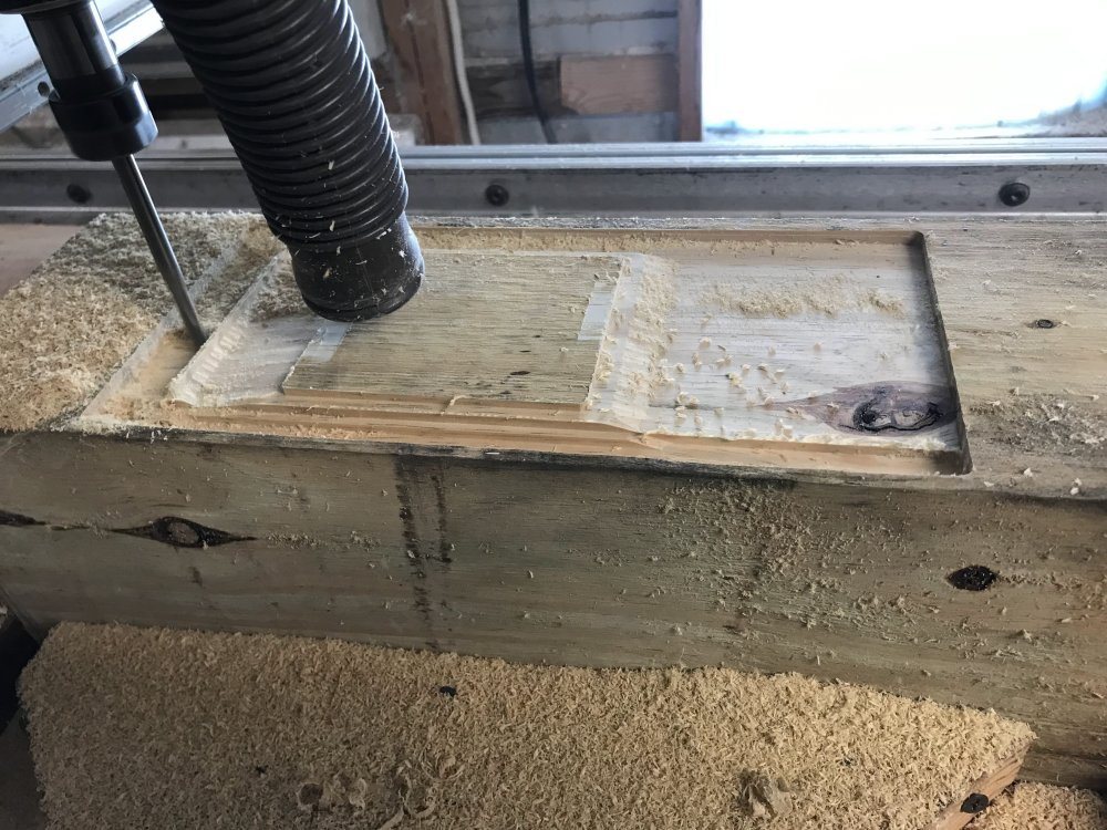
Here I start the machine and it does a lot of the work for me.
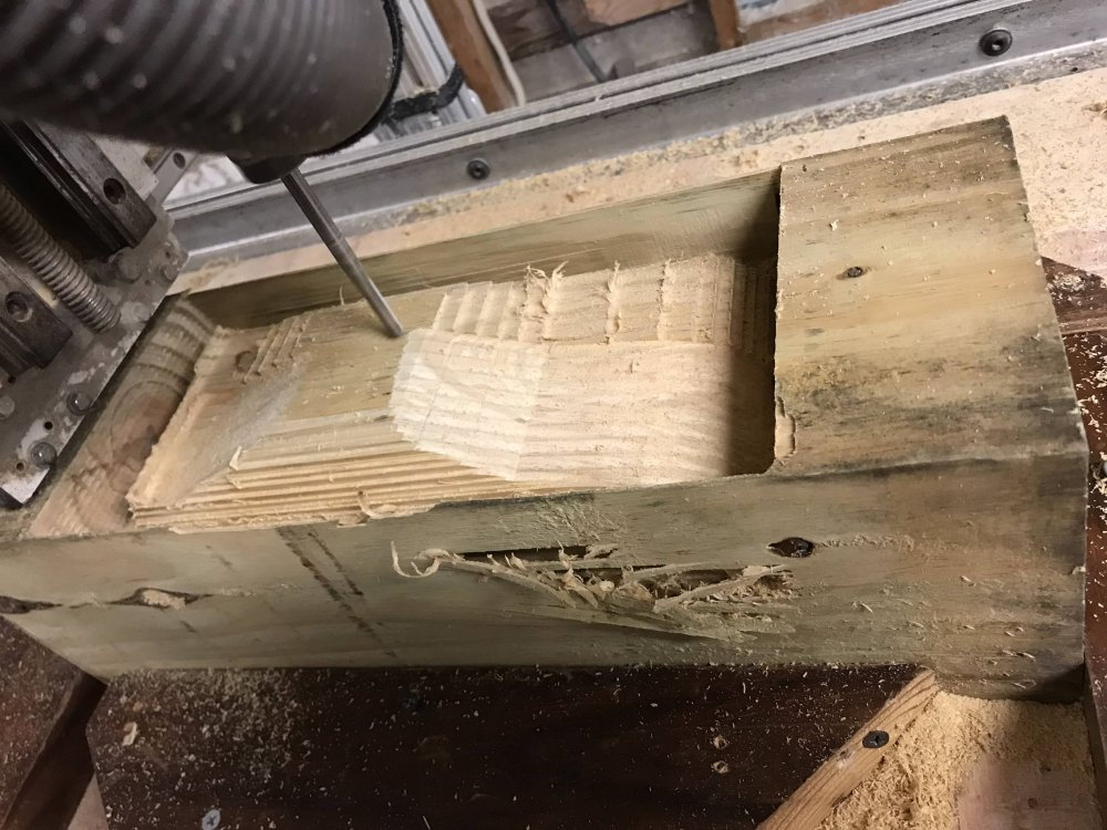
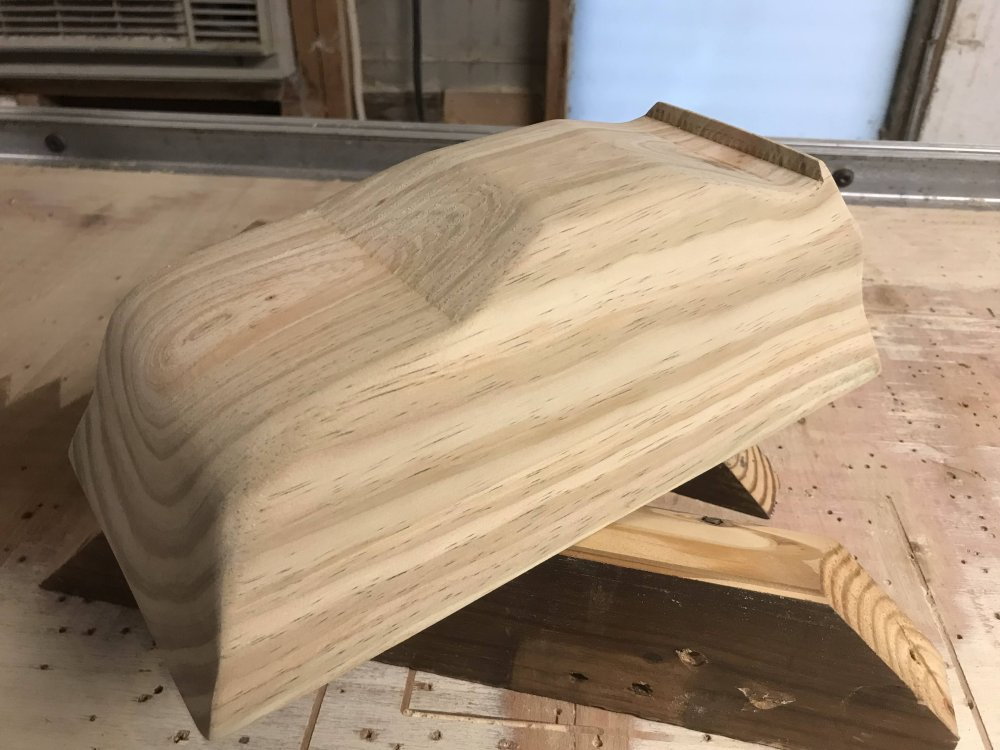
I can use a ball end mill for a smoother finish. But, for this plug I will sand it to the final shape by hand so I just want it roughed out.
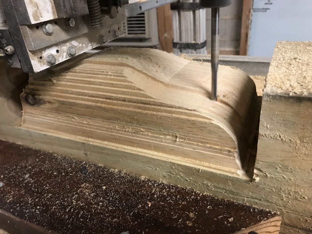
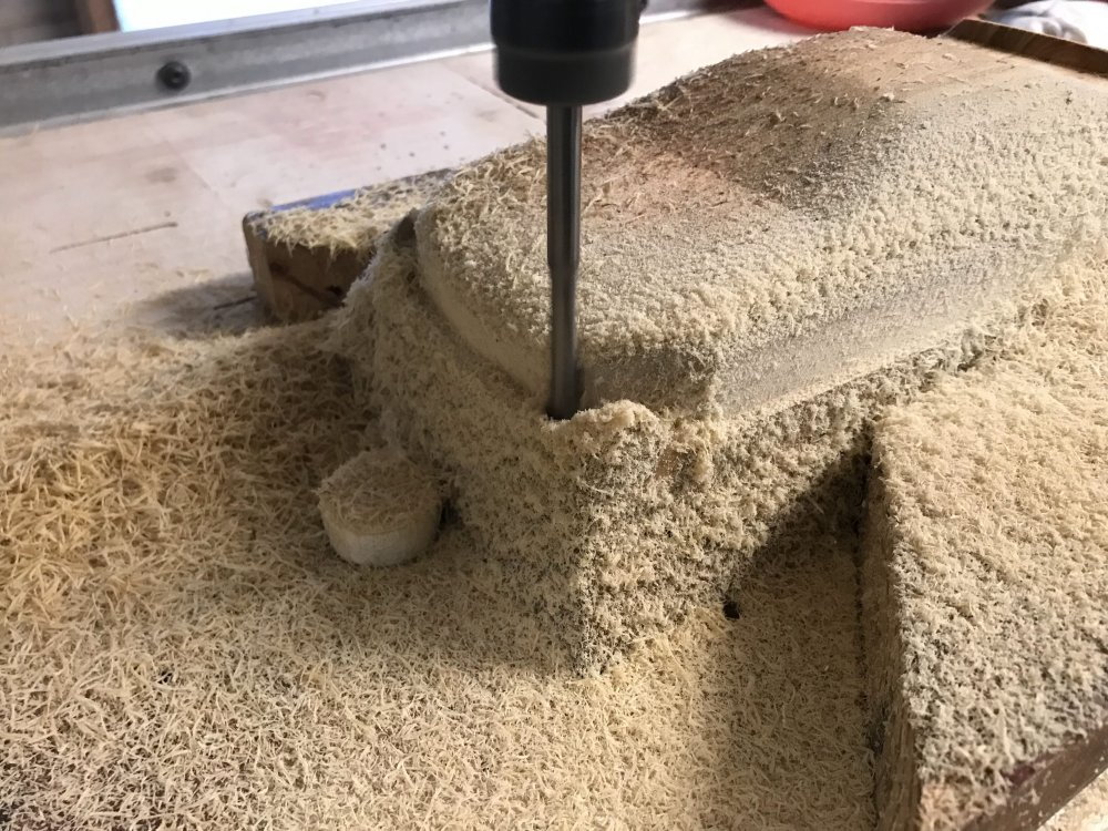
The plug is looking just like I drew it.
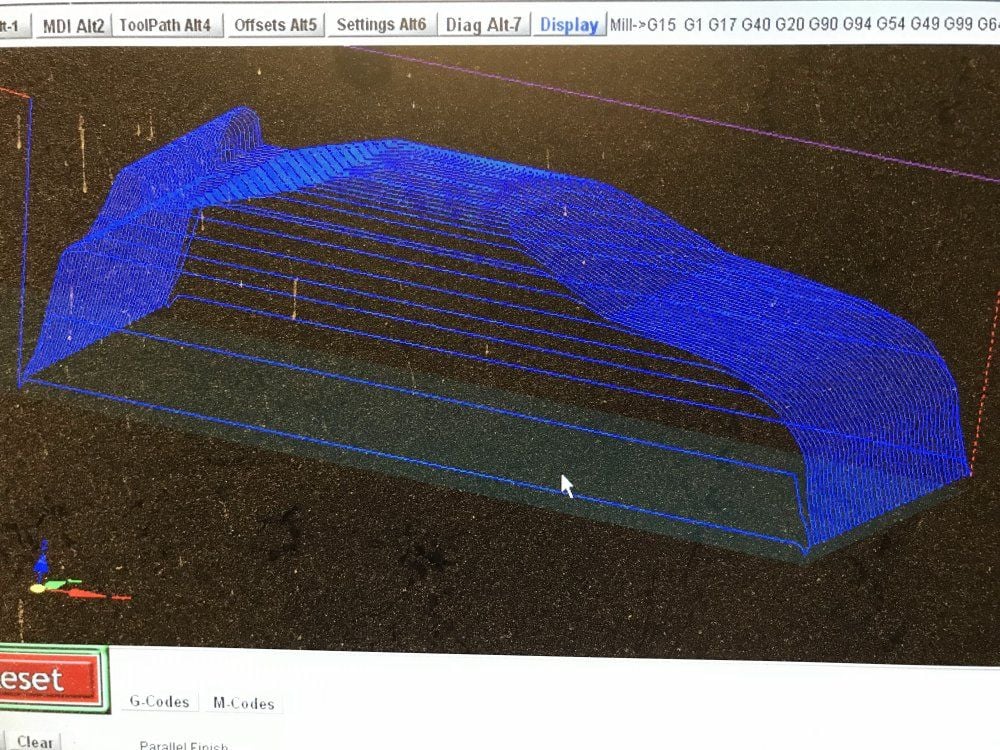
Here is a look at the tool path for the finish pass.
And here is a look at the results.
My custom wood plug is looking pretty good so far.
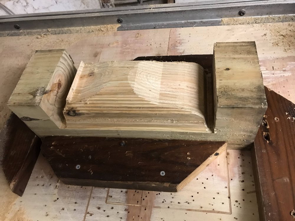
I will flip the plug and remove about half of the remaining wood below the plug. The wood I leave is called a "buck". It is shaped and used to help make forming a body much easier.
I am going to make the plug and the buck as one unit. You could make each and glue them together. That is really the easiest way. But, I like a challenge. So here goes.
Before I start sanding I will cut off the extra material on the ends.
I want to note that you do not need a vacuum forming machine to pull a good body. IMO all you need is the right material, a good plug, a even heat source to heat the plastic
and you can use a flat surface with only one hole in it to form a good body. And "yes" almost any shop vac will do the job if you use only one hole. Making a good plug and using a
buck is the secret. In case you are wondering "The size of the hole should be the same size your shop vac hose fits into".
I will create a simple 3D drawing of the plug and cut it from a solid block of wood. (a 6X6 cut 16" long)
Here is a look at how I do it....
First I draw a side view of the body I want to make and then I draw a view of the rear. I then put those in my CAD program.
Then I create a solid shape using the two views. I also add a bottom to the drawing which helps make using the plug very easy. (more on this later)
I cut the 6X6 to 16" long.
Then I attach the 6X6 to the cnc machine for cutting. You could also draw your profile on the side and back of the block and carve it by hand if you do not have a cnc machine that will do the job.
As you will see, I had no issue cutting the 6X6 block to shape on my machine.
Here I start the machine and it does a lot of the work for me.
I can use a ball end mill for a smoother finish. But, for this plug I will sand it to the final shape by hand so I just want it roughed out.
The plug is looking just like I drew it.
Here is a look at the tool path for the finish pass.
And here is a look at the results.
My custom wood plug is looking pretty good so far.
I will flip the plug and remove about half of the remaining wood below the plug. The wood I leave is called a "buck". It is shaped and used to help make forming a body much easier.
I am going to make the plug and the buck as one unit. You could make each and glue them together. That is really the easiest way. But, I like a challenge. So here goes.
Before I start sanding I will cut off the extra material on the ends.
I want to note that you do not need a vacuum forming machine to pull a good body. IMO all you need is the right material, a good plug, a even heat source to heat the plastic
and you can use a flat surface with only one hole in it to form a good body. And "yes" almost any shop vac will do the job if you use only one hole. Making a good plug and using a
buck is the secret. In case you are wondering "The size of the hole should be the same size your shop vac hose fits into".
01-25-2023, 08:37 PM
#43
Thread Starter
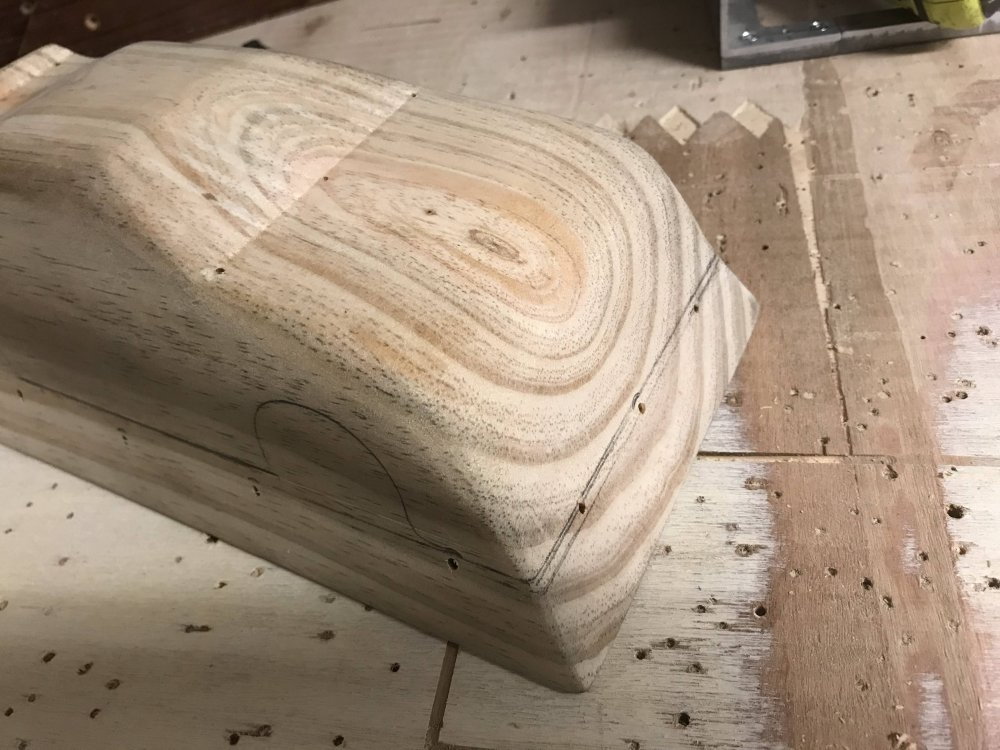
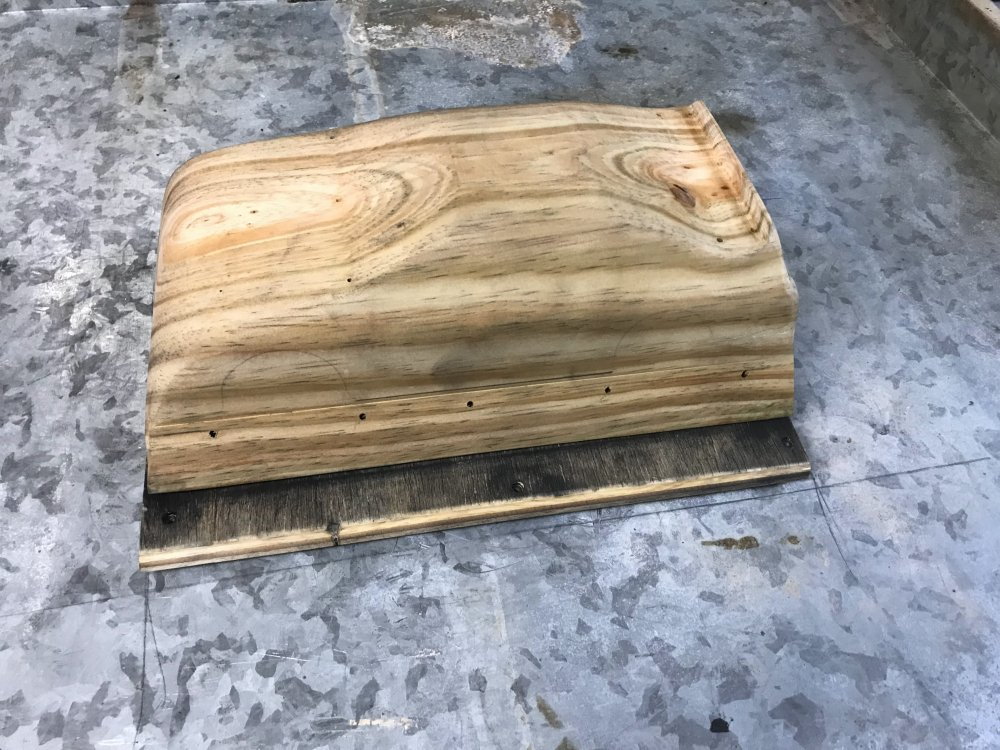
Here are some images as I finished the wood plug.
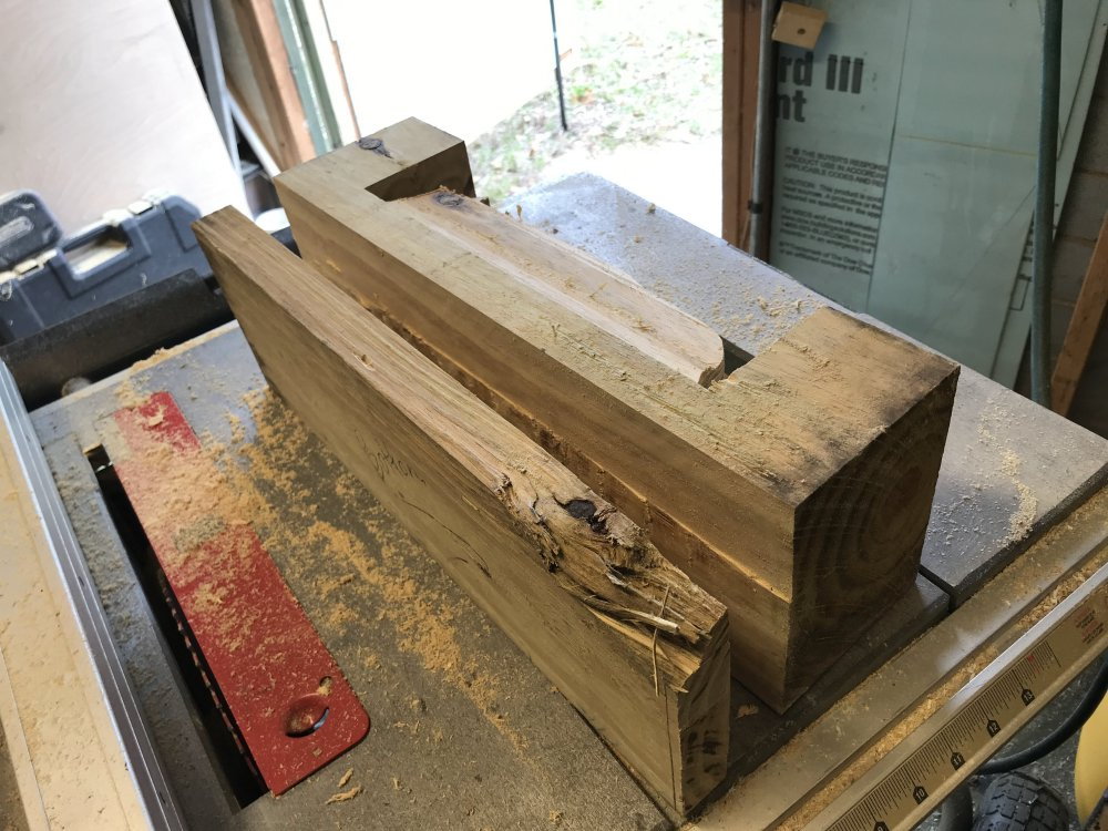
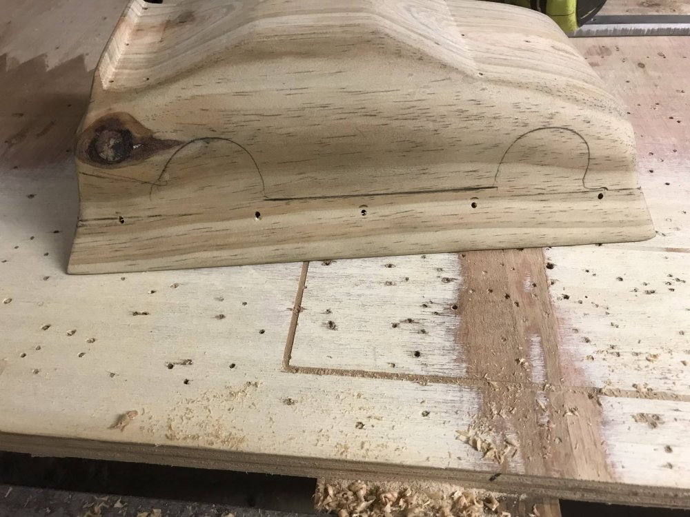
Here I used the table saw to remove about an inch off the buck.

Then I cut the bottom of the buck flat.
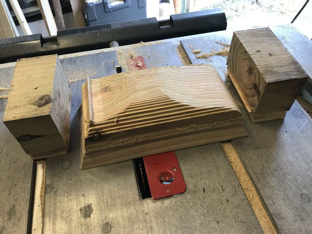
Then I cut off the ends so I can get to sanding.
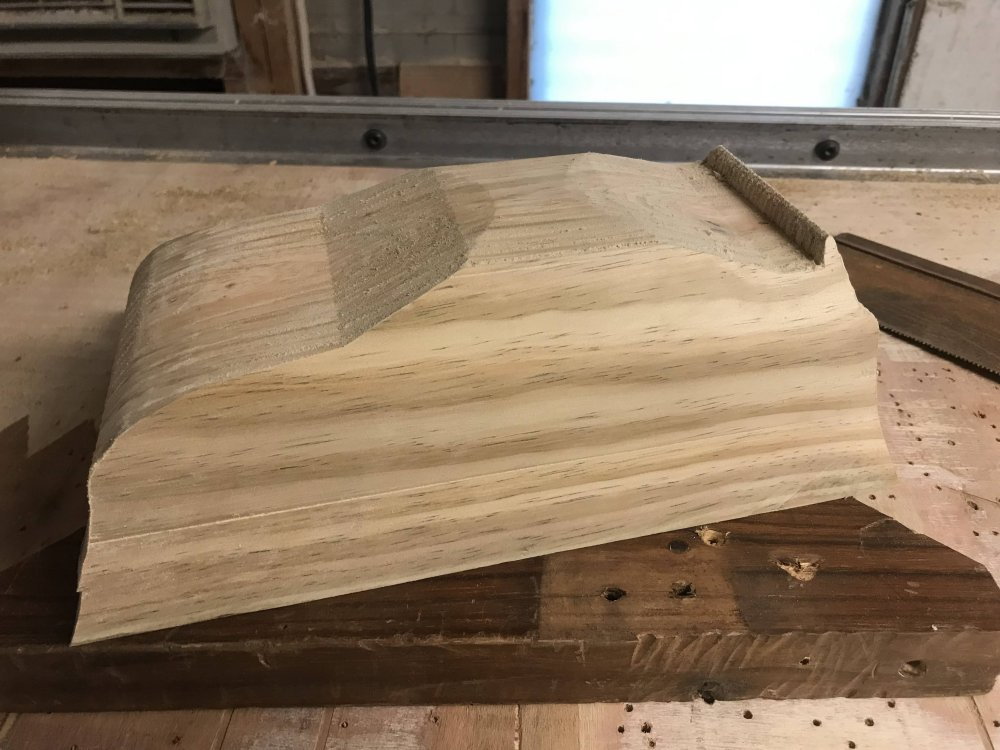
The belt sander makes sanding a lot faster. Just be sure and not lose the body lines.
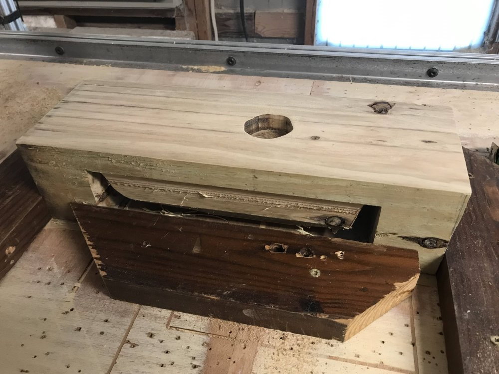
And now it is ready for the holes.
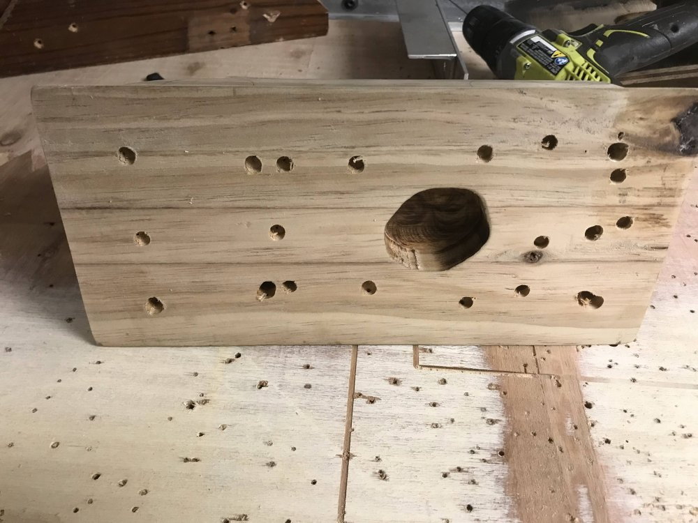
Holes are drilled to help pull the material to the plug during forming.
Drill small holes (1/16") where there are inside corners or curves.
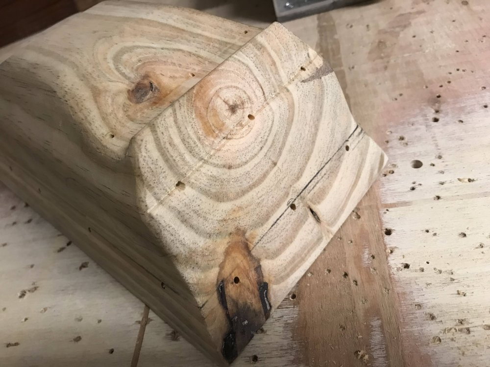
Notice I have 3 holes at the base of the windshield.
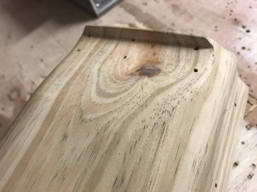
And 6 holes at the trunk lid.
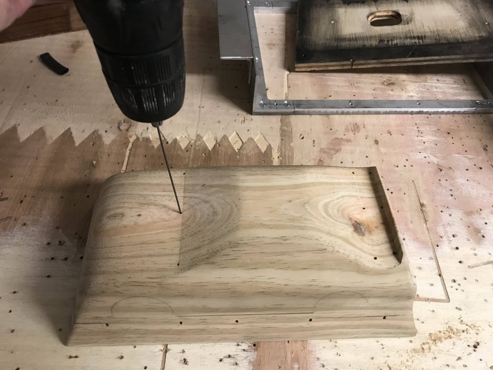
Then drill the holes out the bottom of the plug. (I use a small wire with a flat end for this and push it through as it spins.
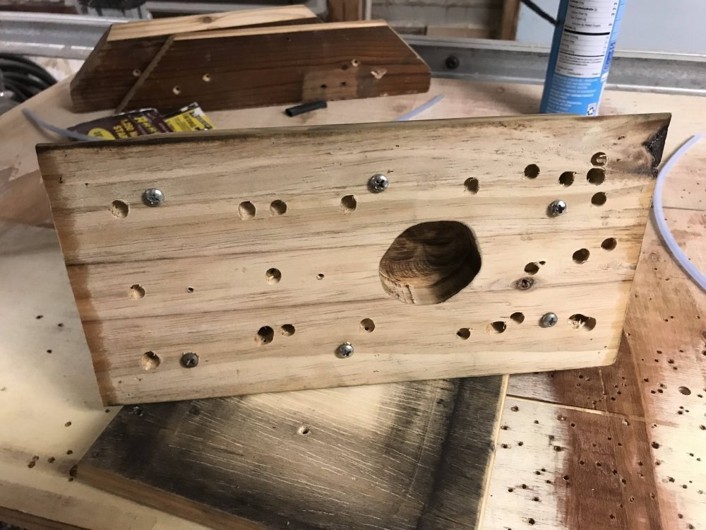
I then open the holes up at the exit point with a 1/4" bit. I also add screws that are used to elevate the buck off the buck base board.
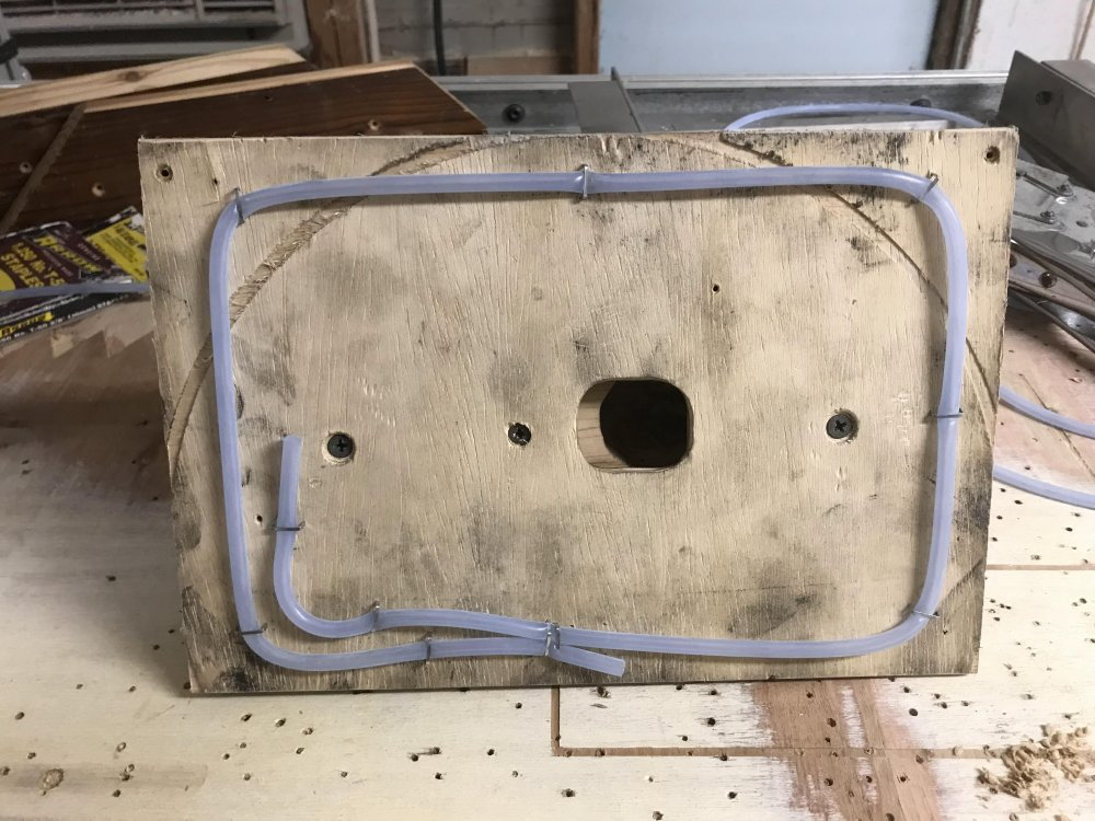
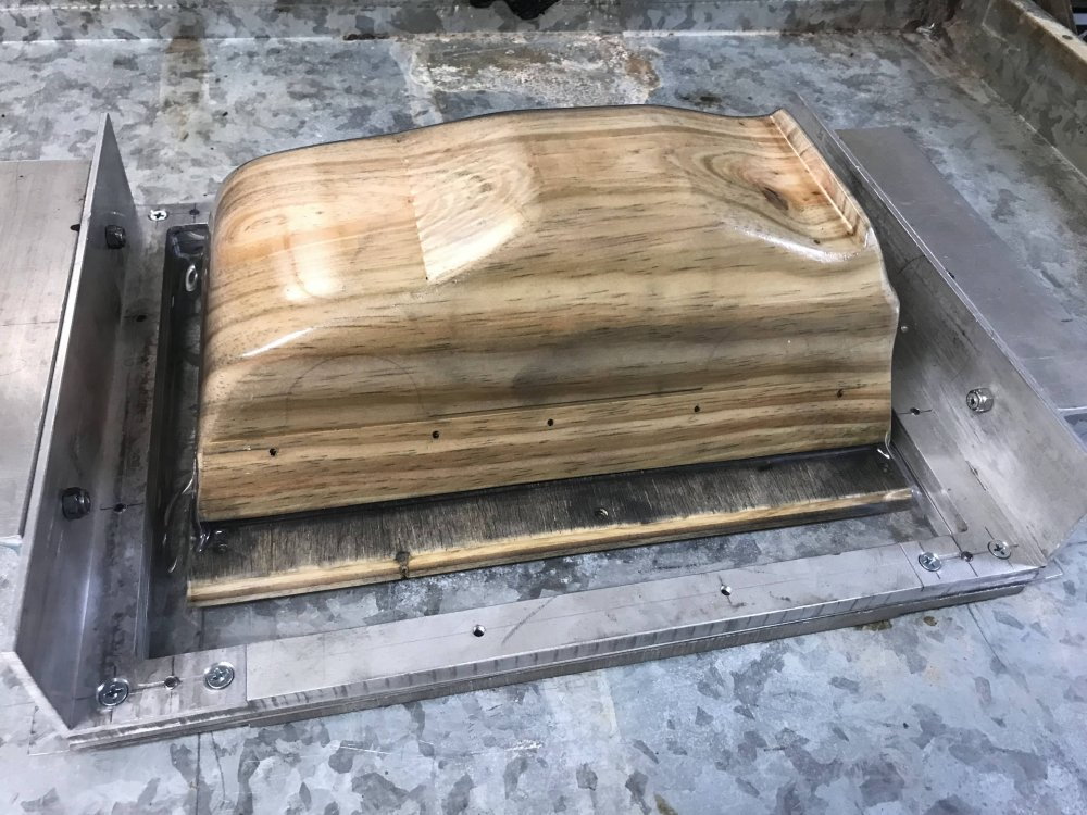
Then I add the base board and run a seal (fuel tubing) around the edge to support the base and to seal it to the vacuum source.
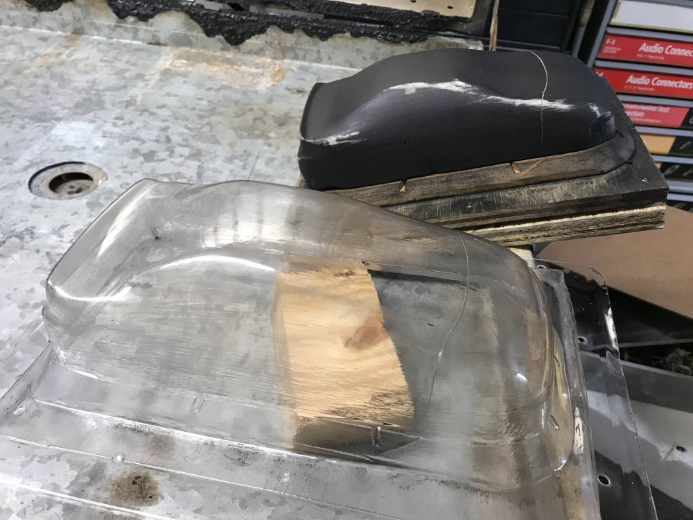
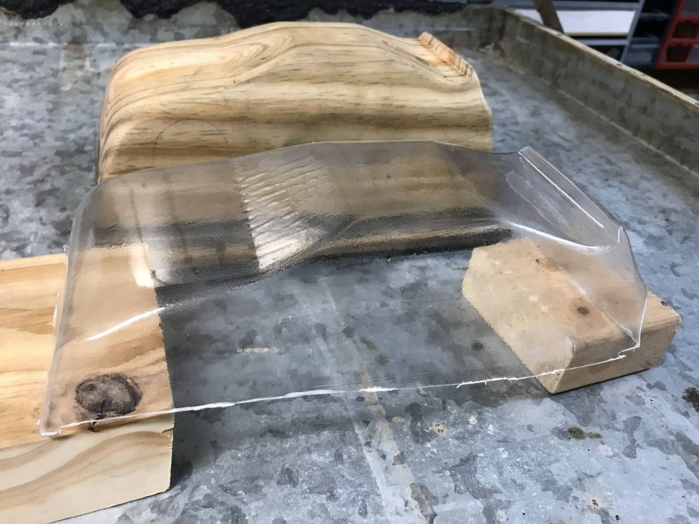
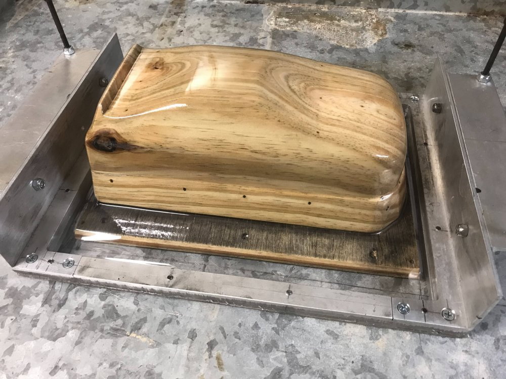
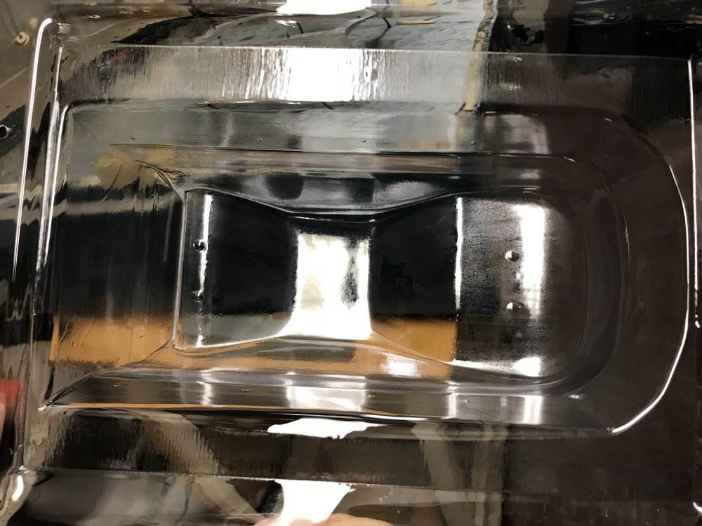
Here the plug and base have been coated with cooking spray and are ready for the first pull.
Here is a look at the first pull. Look close as there is a PETG body that has just been formed to the plug.
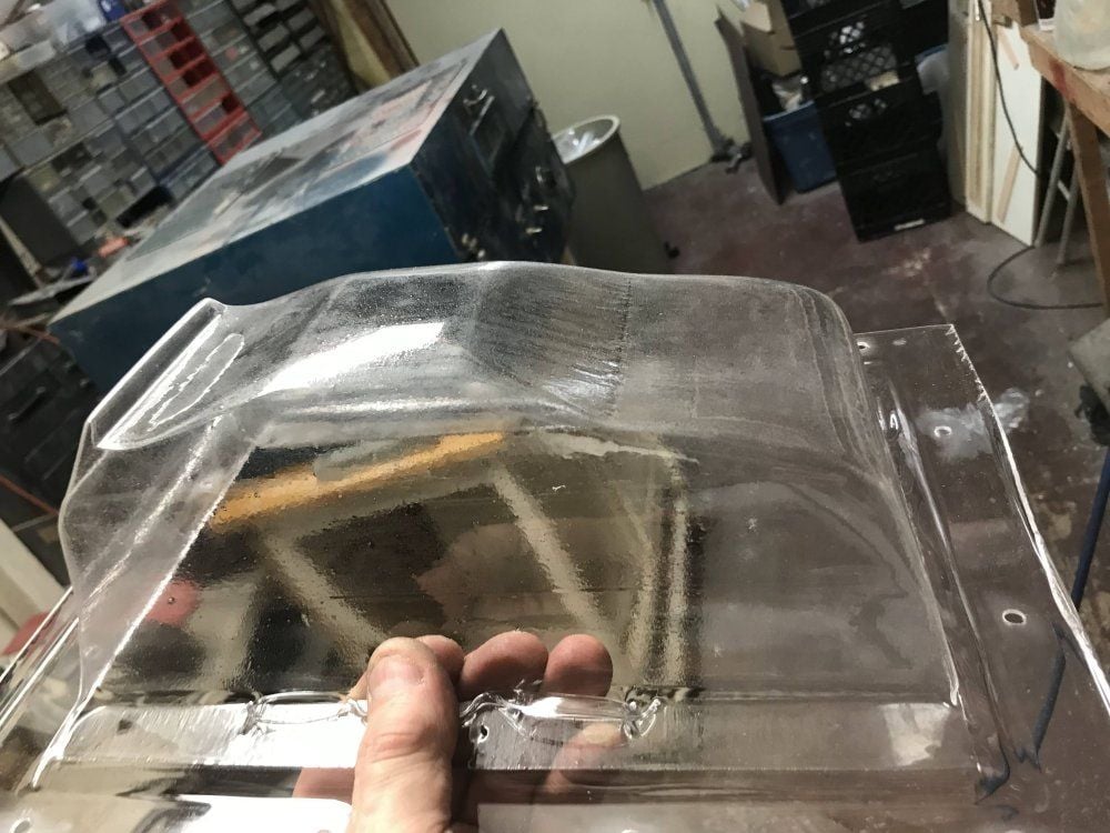
Not to bad for what was a 6X6 hunk of wood yesterday and today it is a working body plug.
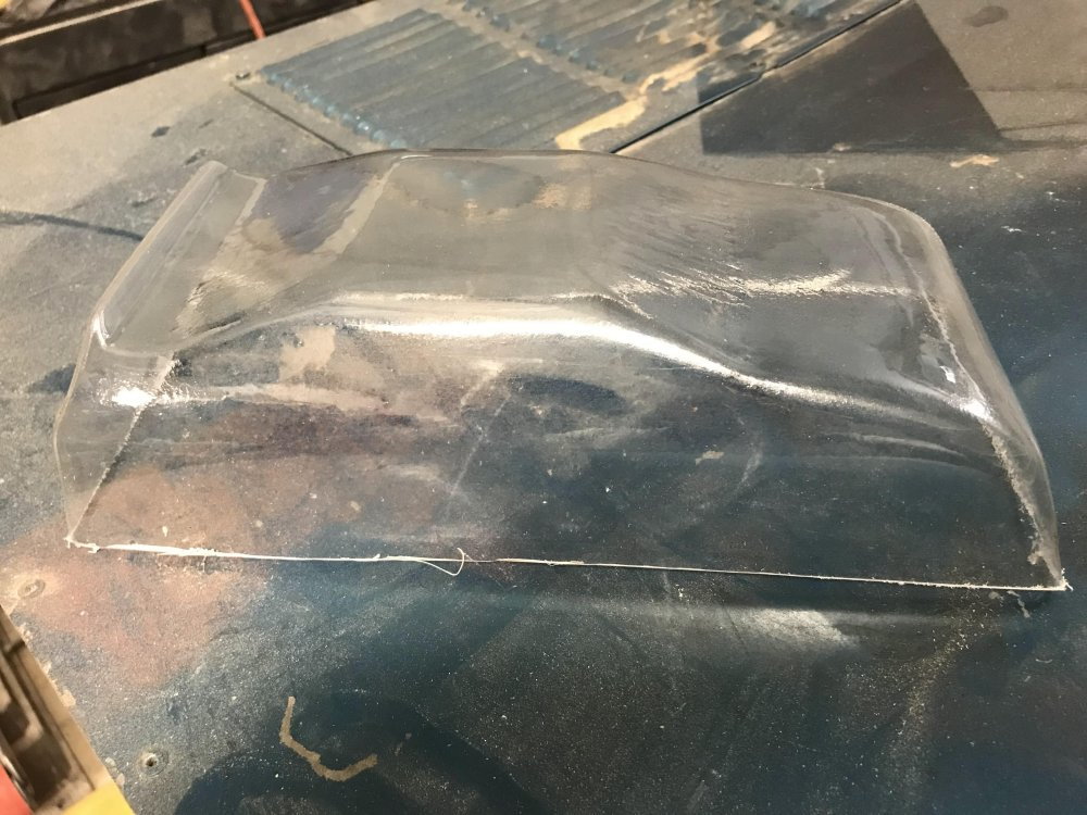
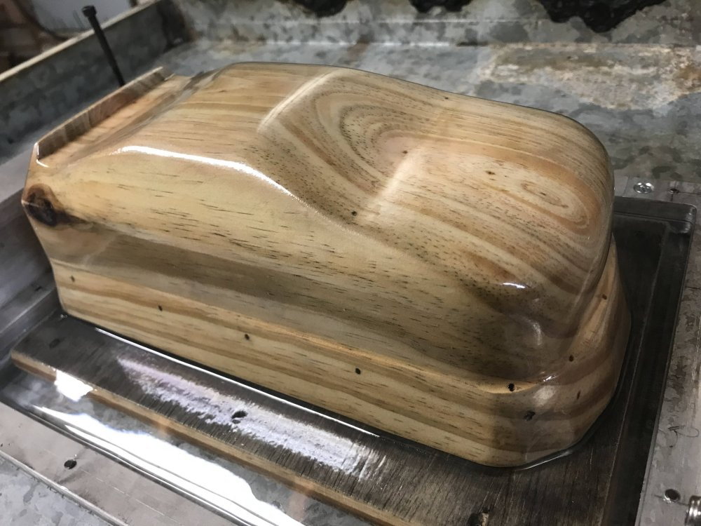
After removing the extra material this is what I get.
And the other side looks good as well.
I will sand out the windshield to remove the lines in the plug. I didn't see them until I pulled the first body.
I am also going to shorten the front bumper area on the plug. I can see I have room in the front I want to get rid of. I thought this might be the case because I made the plug larger as it is easier to remove material then it is to add it.
I hope you have enjoyed the information I have provided on how I create my own custom plugs for vacuum forming.
It is not hard to do even if you do not have a cnc machine. It just takes more time to get it roughed out. The finish side of the project is the same.
If you have questions or if there is something I did not cover in this project just ask and I am always glad to help if I can.
And to think this project started because I wanted to design and build a simple small car I could run on a concrete pad I have in my front yard.
I now have about 10,000 laps on my test car and everything is holding up just fine. This car is a lot of fun to drive when the lap times are being called out.
I am running Trackmate ver 7.3 from a tablet and it has run flawless so far. (lap times can be heard is a few of the video clips I have posted in this thread)
Let me know if I missed anything.
Here I used the table saw to remove about an inch off the buck.
Then I cut the bottom of the buck flat.
Then I cut off the ends so I can get to sanding.
The belt sander makes sanding a lot faster. Just be sure and not lose the body lines.
And now it is ready for the holes.
Holes are drilled to help pull the material to the plug during forming.
Drill small holes (1/16") where there are inside corners or curves.
Notice I have 3 holes at the base of the windshield.
And 6 holes at the trunk lid.
Then drill the holes out the bottom of the plug. (I use a small wire with a flat end for this and push it through as it spins.
I then open the holes up at the exit point with a 1/4" bit. I also add screws that are used to elevate the buck off the buck base board.
Then I add the base board and run a seal (fuel tubing) around the edge to support the base and to seal it to the vacuum source.
Here the plug and base have been coated with cooking spray and are ready for the first pull.
Here is a look at the first pull. Look close as there is a PETG body that has just been formed to the plug.
Not to bad for what was a 6X6 hunk of wood yesterday and today it is a working body plug.
After removing the extra material this is what I get.
And the other side looks good as well.
I will sand out the windshield to remove the lines in the plug. I didn't see them until I pulled the first body.
I am also going to shorten the front bumper area on the plug. I can see I have room in the front I want to get rid of. I thought this might be the case because I made the plug larger as it is easier to remove material then it is to add it.
I hope you have enjoyed the information I have provided on how I create my own custom plugs for vacuum forming.
It is not hard to do even if you do not have a cnc machine. It just takes more time to get it roughed out. The finish side of the project is the same.
If you have questions or if there is something I did not cover in this project just ask and I am always glad to help if I can.
And to think this project started because I wanted to design and build a simple small car I could run on a concrete pad I have in my front yard.
I now have about 10,000 laps on my test car and everything is holding up just fine. This car is a lot of fun to drive when the lap times are being called out.
I am running Trackmate ver 7.3 from a tablet and it has run flawless so far. (lap times can be heard is a few of the video clips I have posted in this thread)
Let me know if I missed anything.
01-25-2023, 10:17 PM
#44
Thread Starter
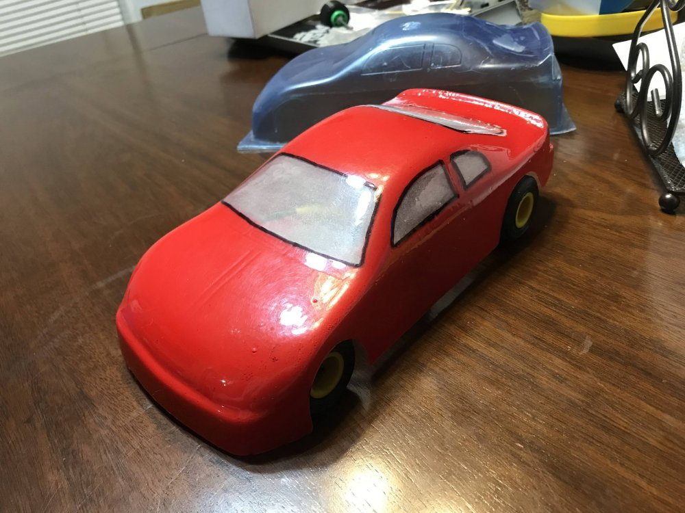
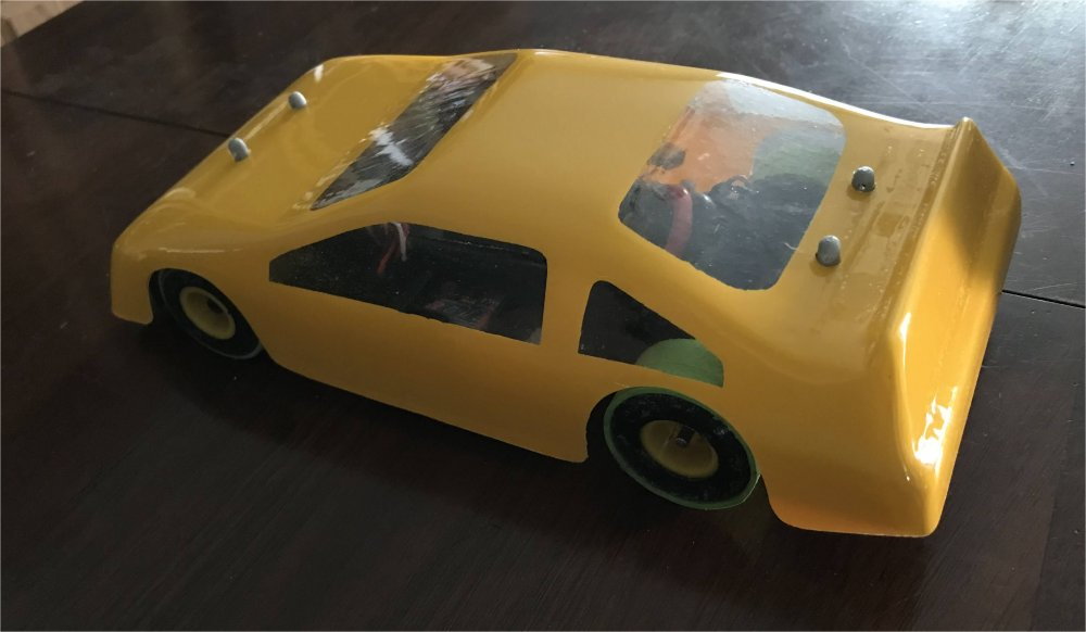
Here is a look the first body pulled from the wood plug just after the vinyl window mask was put on.
I placed the body over a built chassis and marked the location for the body pin holes. It is much easier to mark them before the paint goes on.
Right side
And now for the hardest part of this project. Waiting for the paint to dry!
I placed the body over a built chassis and marked the location for the body pin holes. It is much easier to mark them before the paint goes on.
Right side
And now for the hardest part of this project. Waiting for the paint to dry!

 01-26-2023, 05:33 PM
#47
Thread Starter
Here is a look at how I updated the front of the wood plug.
I mounted the plug back to the cnc machine and created a tool path of what I wanted.

Looking good.
Then I cut it down to the top of the buck. I then gave it a good sanding and it was ready for a test pull.
So it was time to heat up some PETG.
Almost ready.
Here is a look at the pull while it cools.
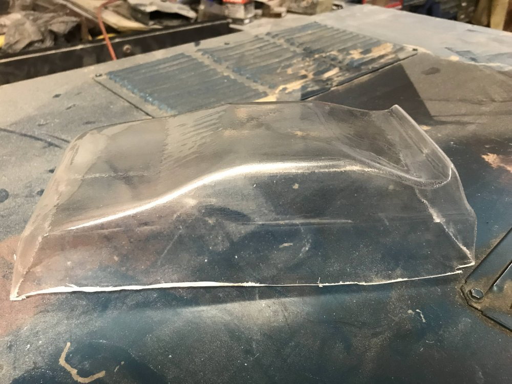
The front end looks good.
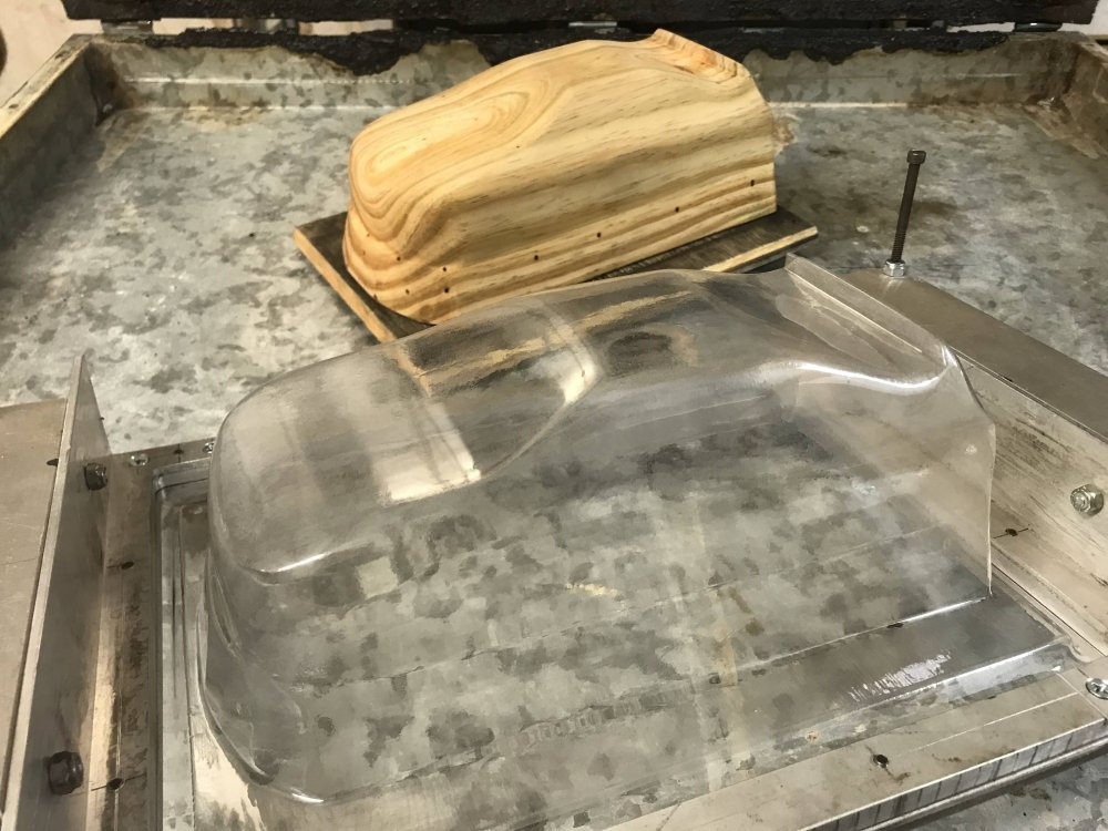
Here is the pull with the plug removed. Notice I also removed the lines in the windshield. It just needed a bit more sanding.
I pulled a second body to be sure the plug was good.
The fit is perfect.
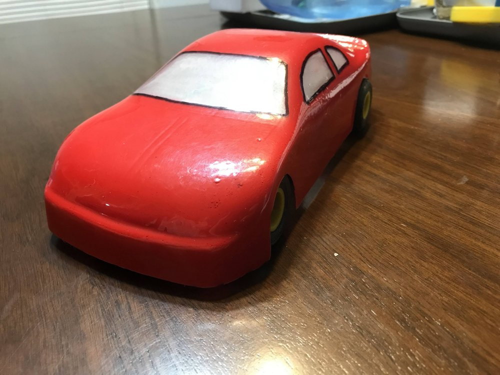
Here I have cut the body before painting so I could check the fit.
Here are a few more images of the result of my efforts.
That looks pretty good to me.
Yep that will race!
I mounted the plug back to the cnc machine and created a tool path of what I wanted.
Looking good.
Then I cut it down to the top of the buck. I then gave it a good sanding and it was ready for a test pull.
So it was time to heat up some PETG.
Almost ready.
Here is a look at the pull while it cools.
The front end looks good.
Here is the pull with the plug removed. Notice I also removed the lines in the windshield. It just needed a bit more sanding.
I pulled a second body to be sure the plug was good.
The fit is perfect.
Here I have cut the body before painting so I could check the fit.
Here are a few more images of the result of my efforts.
That looks pretty good to me.
Yep that will race!

 01-27-2023, 10:32 PM
#49
Thread Starter
Here is a look at the first body pulled from the wood plug after I updated the front end.
I have just updated the wood plug to include body post locations to make mounting the body to the chassis much faster.
Here you can see the body pin locations after the body is removed from the plug.
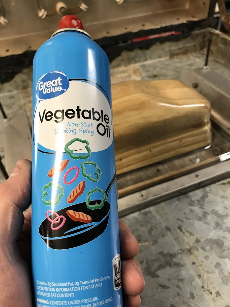
This is what I use on the plug so the formed body comes right off. I spray the plug the buck and the base then rub it in and
after a few minutes I wipe it all off. I may repeat after about 50 bodies pulled if needed. I will link a video below showing the wood plug and how I use
a one hole vacuum setup to pull a body from my custom plug. The trick is in the setup. I use my plug a buck and a base. When you have all 3 working
together you can get the same results. For this project I made the buck and the plug in one piece but you do not have to do it that way. (I did cause I like a challenge)
Just make each and do the prep work then glue them together. Keep in mind that I am using .060 PETG material for this project and it pulls nice with my setup.

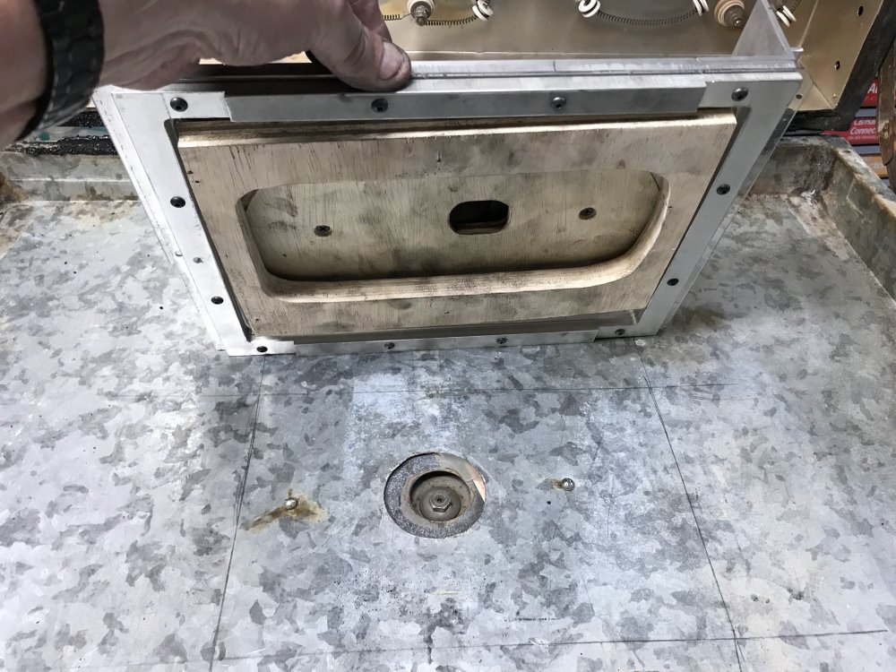
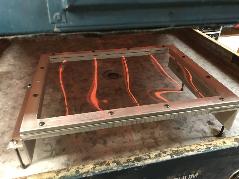
Here is a good look at the top side of the fixture I use to hold the material as it is heating up. Note the single hole right behind the fixture.
About 30 seconds before the material is ready for the pull I open the cabinet and place the plug over that hole. (my vacuum source)
This allows the plug to preheat.

When the plastic is ready I open the cabinet TURN OFF the heat, TURN ON the vacuum and then flip my fixture over and press it down over
the plug so that the material seals at the base. In about two seconds it pulls the material to the plug in one smooth motion. I let the material cool a minute and then remove the material from the plug.
I cut the body from the waste material and it is ready to be fitted to a car chassis. Fun Stuff for sure.
The following short video will show it much better then I have explained it. Enjoy!
Last edited by testfly; 01-27-2023 at 10:37 PM.
01-28-2023, 03:07 PM
#50
Thread Starter
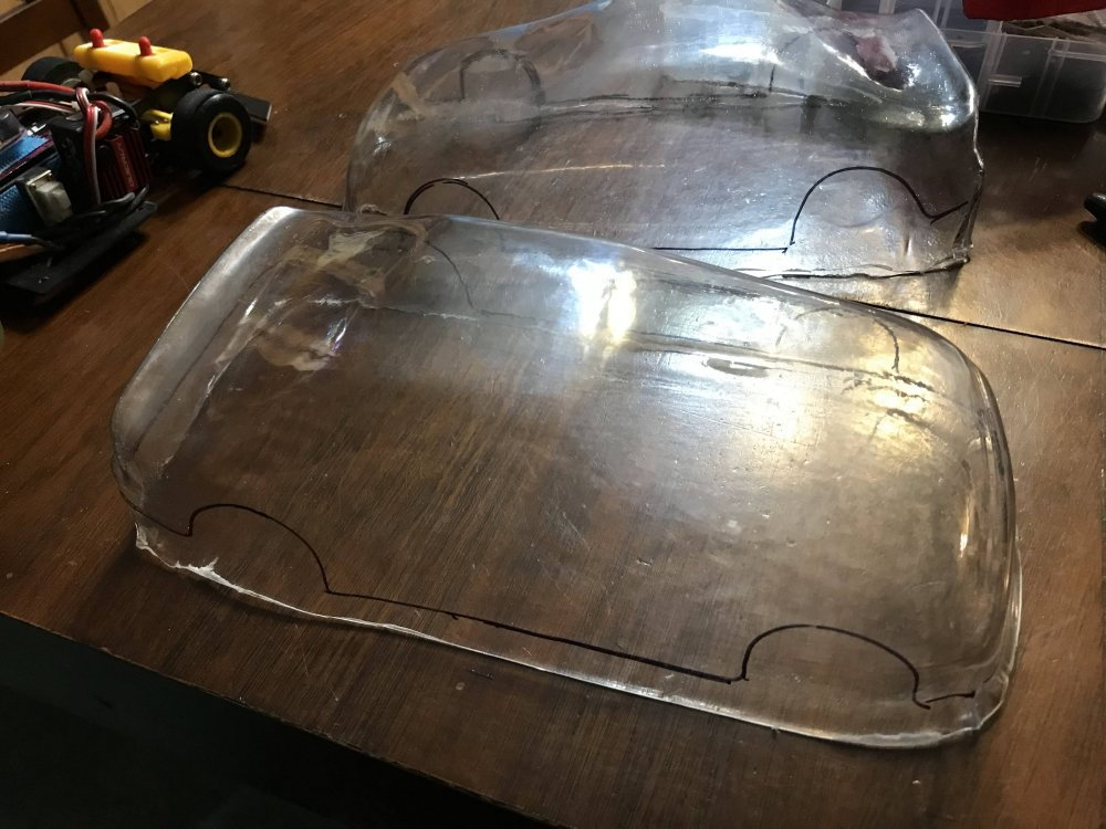
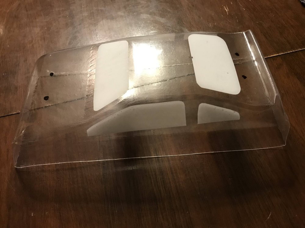
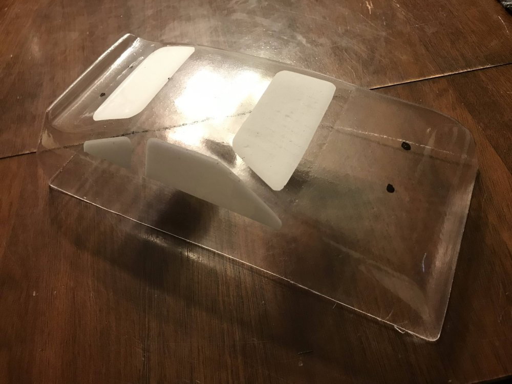
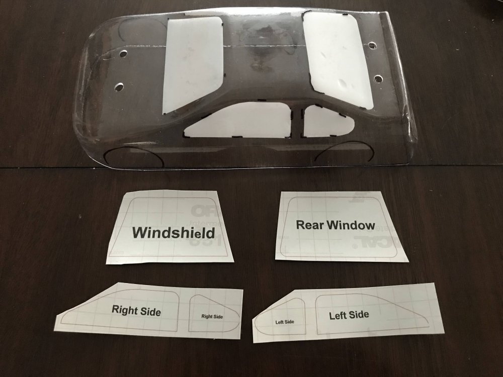
I spent some time creating the window mask for this project.
Here is how I went about it.
The first thing I do is give the body a good washing with a mild soap and water.
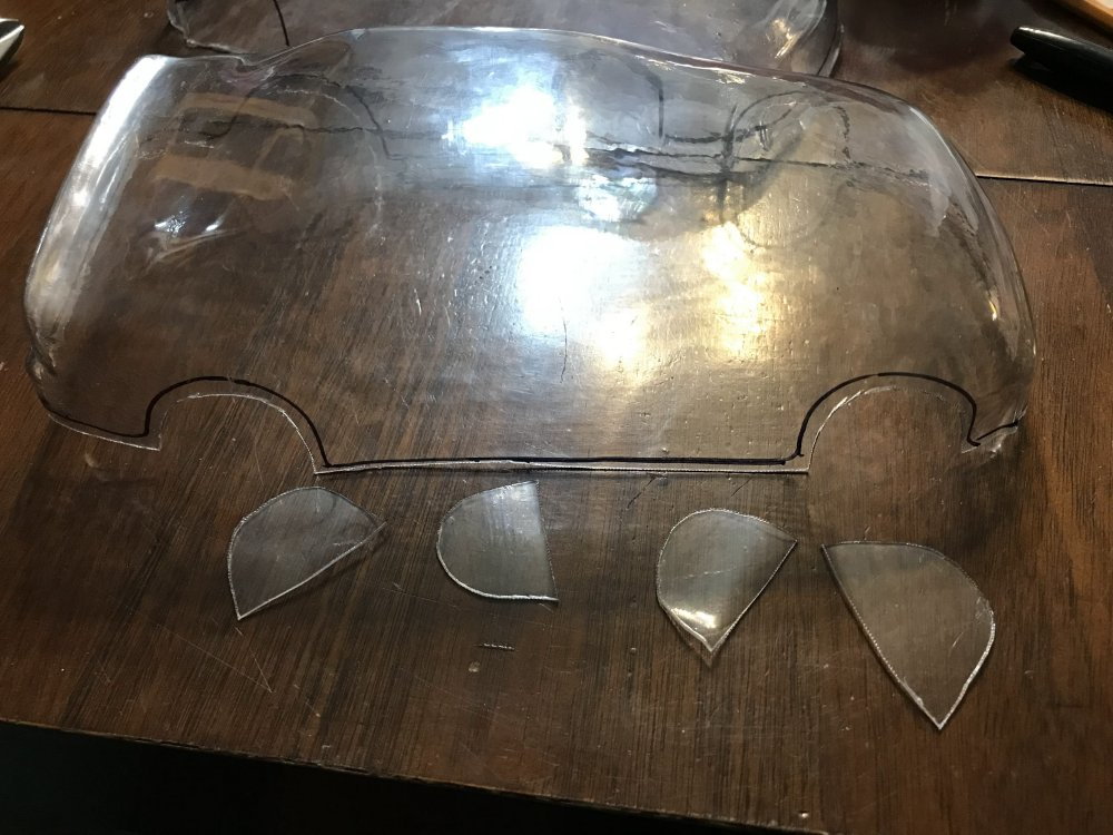
Then I rough cut each window shape until I had the look I wanted.
I held them in place and marked the location on the outside of the body. (you can cover the area to be marked with masking tape so when you remove the tape you remove the marks as well)
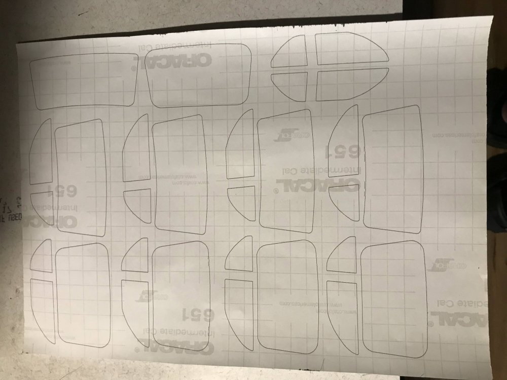
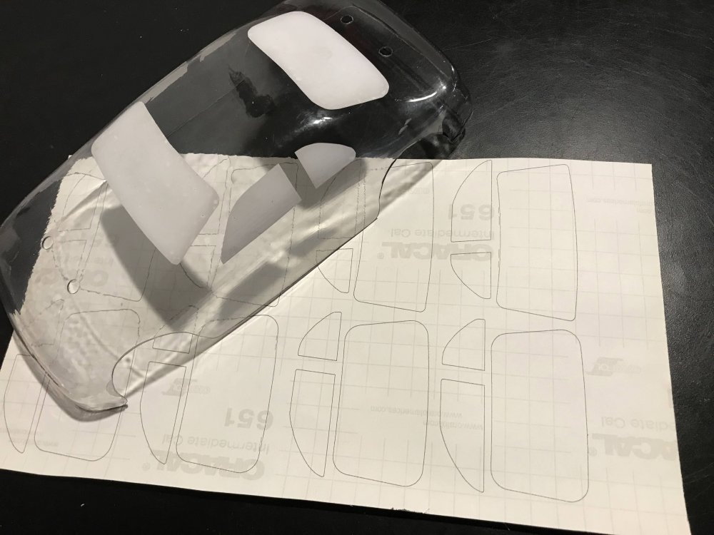
I then took all the shapes and traced them on a sheet of paper.
I then scanned that page and sent it to my CAD program to clean up the lines and curves.
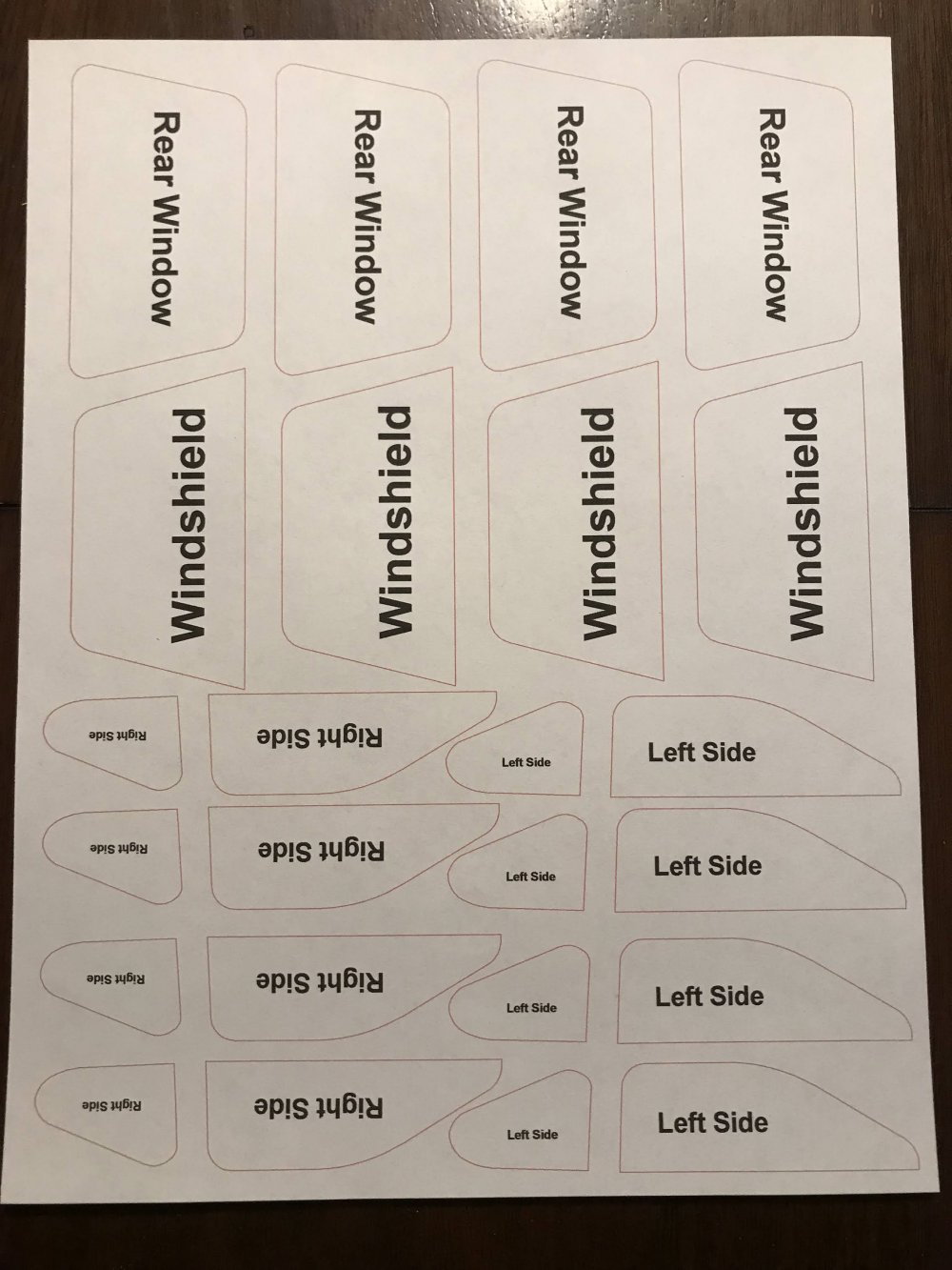
Then I put as many as I could in a 8.5 X 11 area and did a test print on plain paper. I was able to create 4 sets of window mask on a sheet.
I then I cut a sheet of vinyl 8.5 X 11 and placed it so the ink would print on the back side of the vinyl.
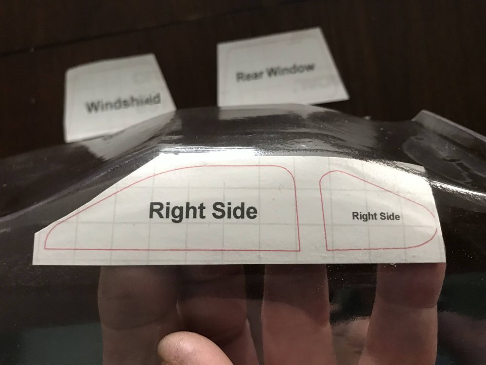
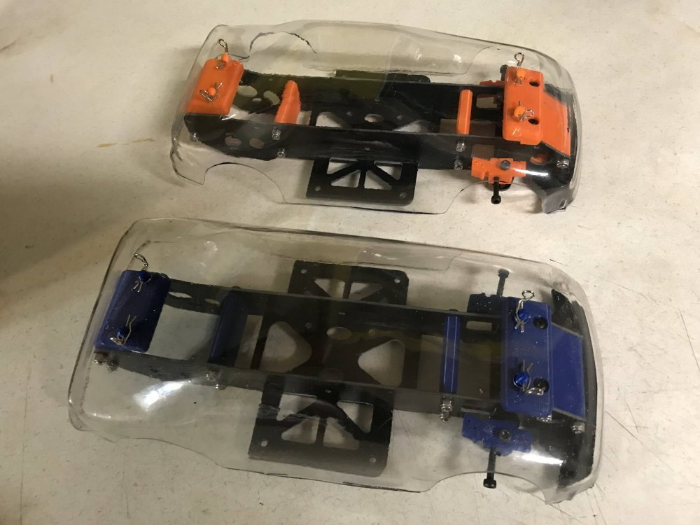
I printed the mask sheet I created and cut a set of window mask from it. I then checked the size and shape of each window..
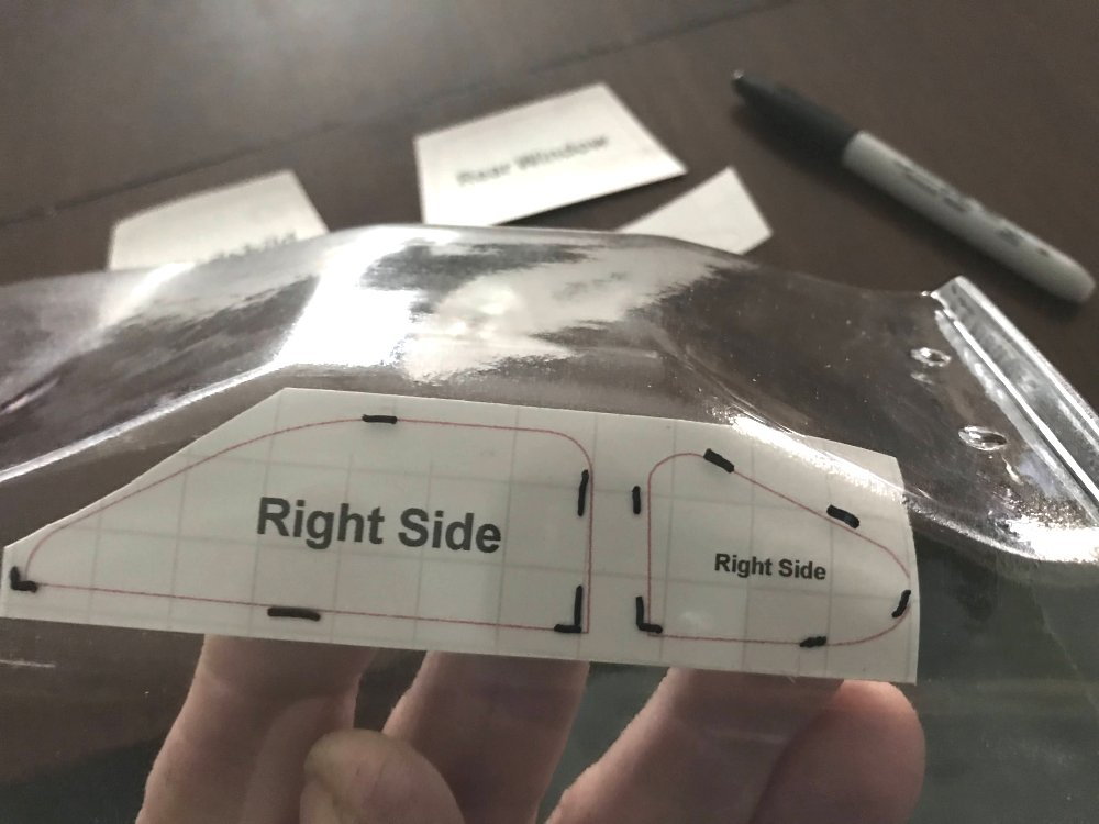
I placed each window and made a few marks on the outside of the body to help place them when I was ready to stick them in place.
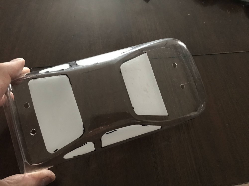
The mask go on the inside of the body before painting and should be carefully removed before the paint cures.
Marking the window locations made placing each mask much easier and faster. Note that after I marked the location of the front and rear side windows I then cut them apart.
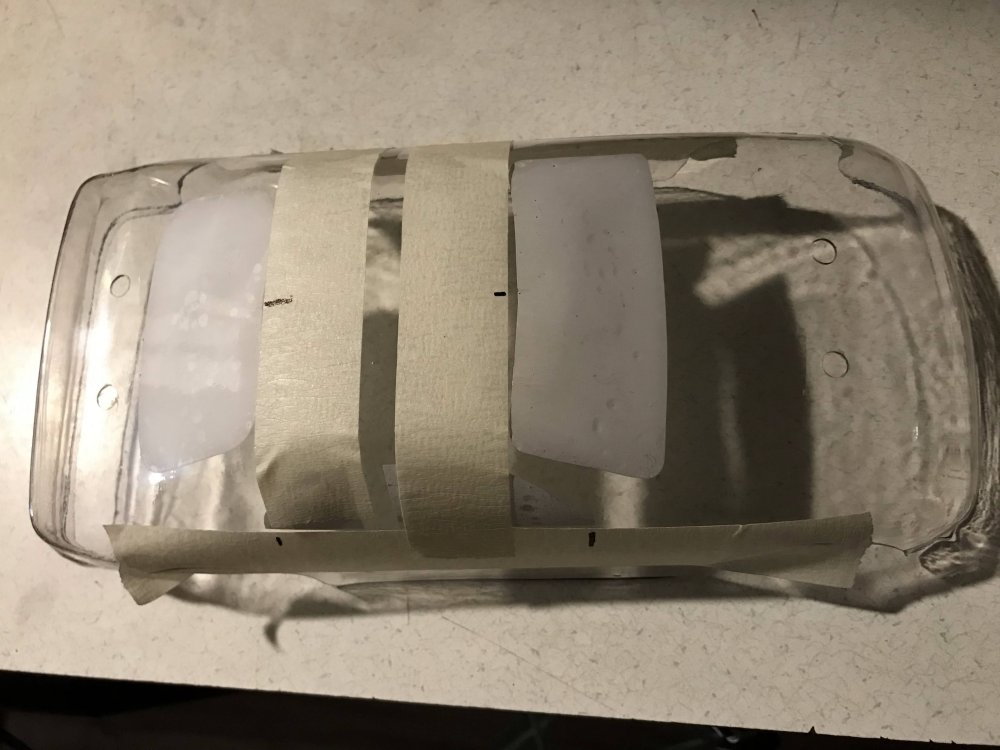
I will tape over the body pin holes and the body will be ready for paint.
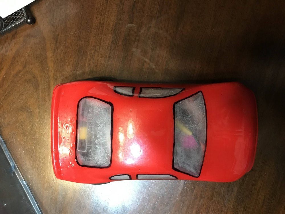
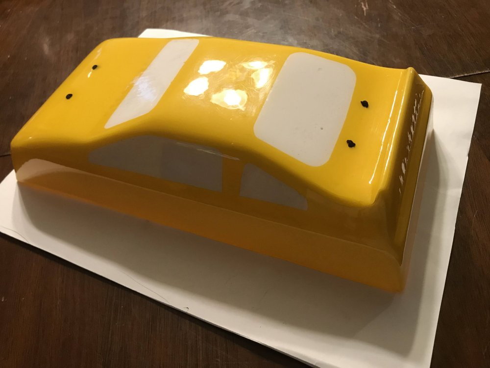
Here I have removed the window mask.
When the paint cures I will add packing tape to protect the paint at the body pin locations.
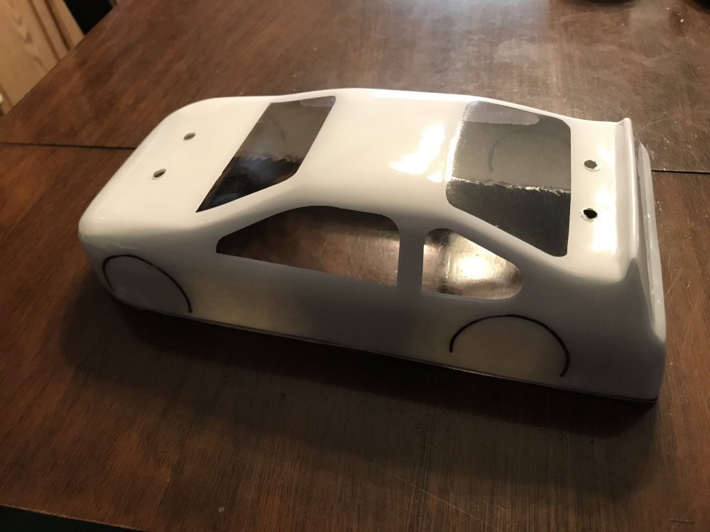
Here it is before taping.
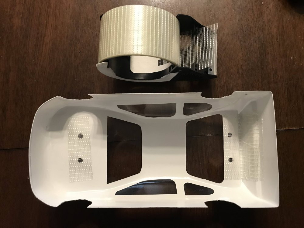
And here it is after taping. Now the body mounts will not rub through the body paint. Notice I also placed tape at the rear to protect the paint.
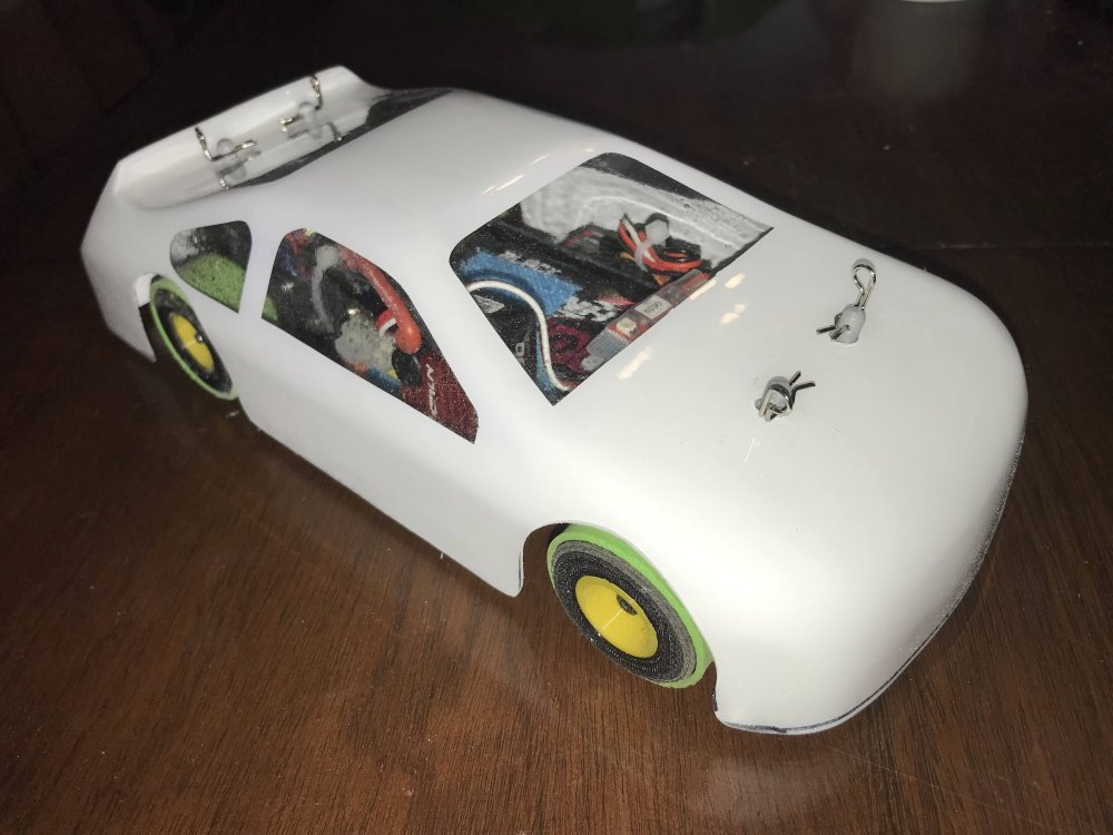
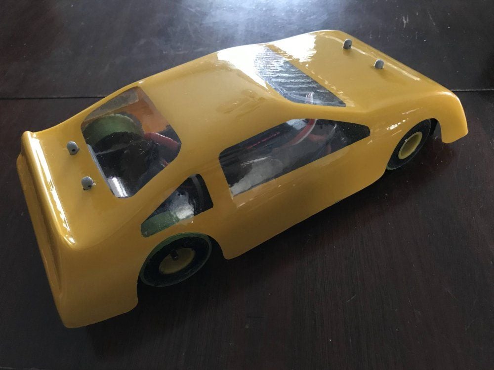
Here is a look after the body was mounted to a chassis.
I need to remove the black marker and it will be ready for some race decals.
Let me know if there is any part of this project I did not cover.
Here is how I went about it.
The first thing I do is give the body a good washing with a mild soap and water.
Then I rough cut each window shape until I had the look I wanted.
I held them in place and marked the location on the outside of the body. (you can cover the area to be marked with masking tape so when you remove the tape you remove the marks as well)
I then took all the shapes and traced them on a sheet of paper.
I then scanned that page and sent it to my CAD program to clean up the lines and curves.
Then I put as many as I could in a 8.5 X 11 area and did a test print on plain paper. I was able to create 4 sets of window mask on a sheet.
I then I cut a sheet of vinyl 8.5 X 11 and placed it so the ink would print on the back side of the vinyl.
I printed the mask sheet I created and cut a set of window mask from it. I then checked the size and shape of each window..
I placed each window and made a few marks on the outside of the body to help place them when I was ready to stick them in place.
The mask go on the inside of the body before painting and should be carefully removed before the paint cures.
Marking the window locations made placing each mask much easier and faster. Note that after I marked the location of the front and rear side windows I then cut them apart.
I will tape over the body pin holes and the body will be ready for paint.
Here I have removed the window mask.
When the paint cures I will add packing tape to protect the paint at the body pin locations.
Here it is before taping.
And here it is after taping. Now the body mounts will not rub through the body paint. Notice I also placed tape at the rear to protect the paint.
Here is a look after the body was mounted to a chassis.
I need to remove the black marker and it will be ready for some race decals.
Let me know if there is any part of this project I did not cover.
Last edited by testfly; 01-28-2023 at 08:18 PM.

