


Bashing a bashed kit
 10-16-2013 | 04:10 PM
#1
Thread Starter

My Feedback: (11)
Here's the plan. I have a .60 sized Super Sportster kit that will be built as a twin. I ordered the twin plans from RCM, and when they get here I'll start the build.
Now the reall bashy part of the plan. I'm going to build it with a high wing, and a twin tail. In doing my resaearch, i stumbled across a full scale plane that i thought would be ideal, the Dinfia IA 45 Querandi, an Argentinian design similar to the Aero Commander . This plane is a high wing pusher twin with twin tails. Our field is fairly rough grass, so I like the high wing design, and will use dural main gear instead of the wire gear. The twin tails should help with engine out flying.
For reliability reasons, I'll be using a pair of new OS FP40s with diesel conversion heads, and each will have an 8 oz tank in the nacelle, and that should give 15 minute flights. I really wanted to go with the pusher engines in the Dinfia design, which would make balancing much easier, but discovered that these bushing type engines don't like to be run as pushers, and along with the hassle of setting up the mufflers led me to go with a tractor setup instead.
I will document the process here, but plan on taking a few months to finish it. This is my first twin, so I will happily accept pointers from the more experienced builders on here. Thanks to all of you for the helpful information I've already read BTW!
 11-07-2013 | 05:52 PM
#2
Thread Starter
My Feedback: (11)
So, how long does a guy have to wait for RCM to send plans anyway? I ordered the Sportster twin plans on 9/2, and I'm still waiting. I can't get them to reply to my e-mails either.
i may have to just go at it on my own, unless somebody here has a set they'd sell/rent/lend..
i may have to just go at it on my own, unless somebody here has a set they'd sell/rent/lend..
12-28-2013 | 11:55 AM
#3
Thread Starter
My Feedback: (11)
Well, it would appear that RCM plans won't be sending the plans I ordered, so after perusing many builds on this site, I designed my own. I designed them with a notch that will key into the upper and lower spars, which should add a bit of strength. I used 1/8" birch ply, and cut a bunch of round holes to lighten them up.
12-28-2013 | 12:10 PM
#4
Thread Starter
My Feedback: (11)
Looks like I needed to re-size my photos!
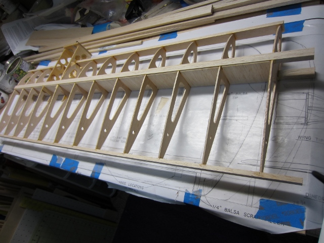
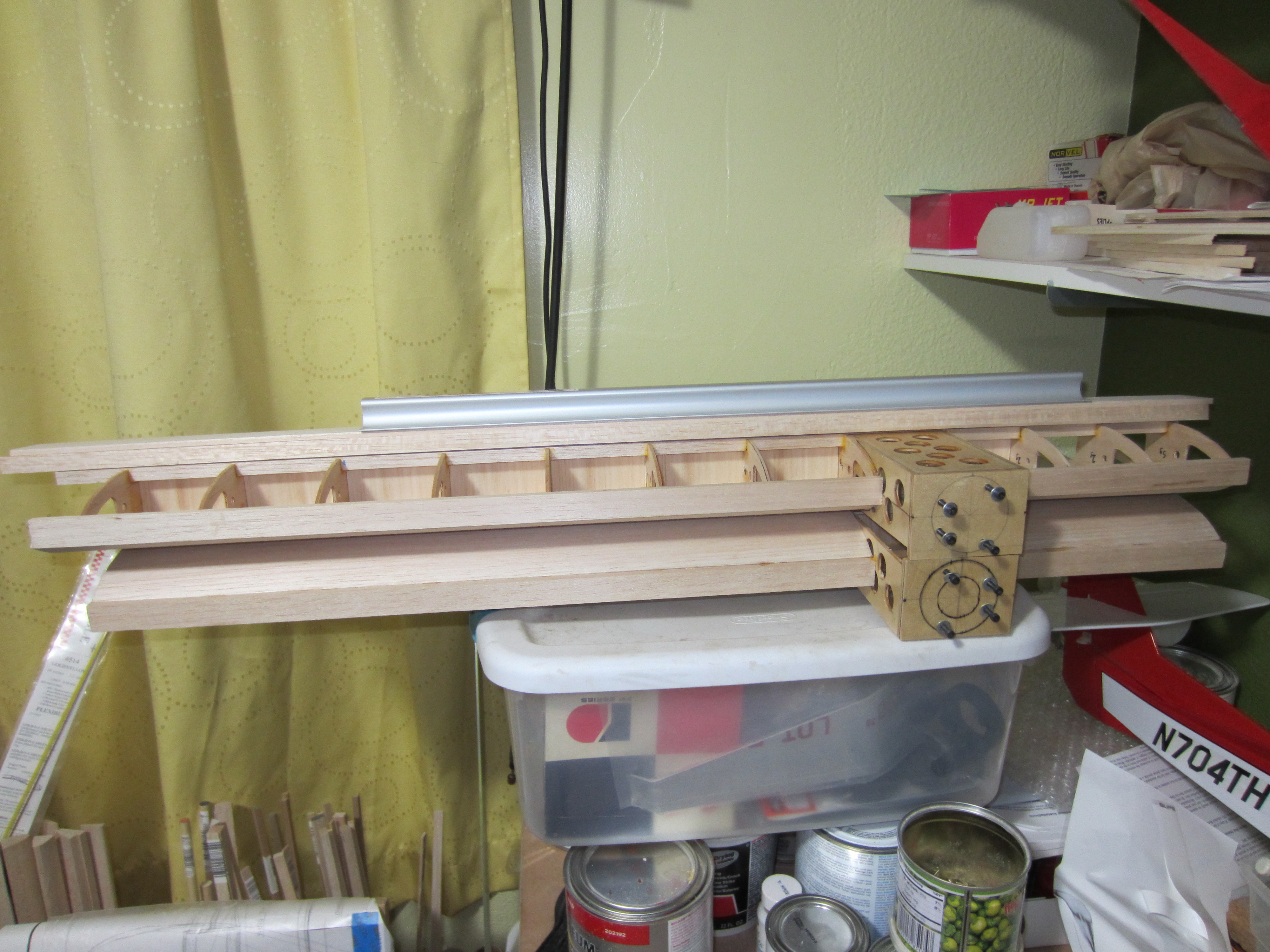
So, part of bashing this kit is lengthening the wing from 61" to 67", and lucky for me, my LHS carries 48" balsa, so I won't have to splice any spars or trailing edges. I laid out the wing plan to have 2 1/2" rib spacing from the center out to the nacelle, the 3" out to the tip. I needed to cut out a couple of extra ribs, then weighed them all so I could bias the weight to the left wing to counter the offset weight of the engines and their pipes.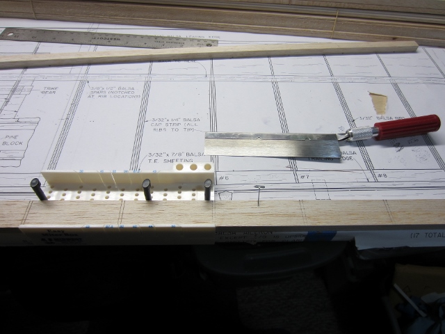
So, part of bashing this kit is lengthening the wing from 61" to 67", and lucky for me, my LHS carries 48" balsa, so I won't have to splice any spars or trailing edges. I laid out the wing plan to have 2 1/2" rib spacing from the center out to the nacelle, the 3" out to the tip. I needed to cut out a couple of extra ribs, then weighed them all so I could bias the weight to the left wing to counter the offset weight of the engines and their pipes.
12-28-2013 | 12:27 PM
#6
Thread Starter
My Feedback: (11)
All the rest of the wing construction is pretty standard stuff, though I did decide to put sheer webs in all the bays, after all, we're carrying a pair of engines and a longer span.
I'm still figuring out how to post all this stuff, so bear with me while I learn.
I'm still figuring out how to post all this stuff, so bear with me while I learn.
12-28-2013 | 12:42 PM
#7
Thread Starter
My Feedback: (11)
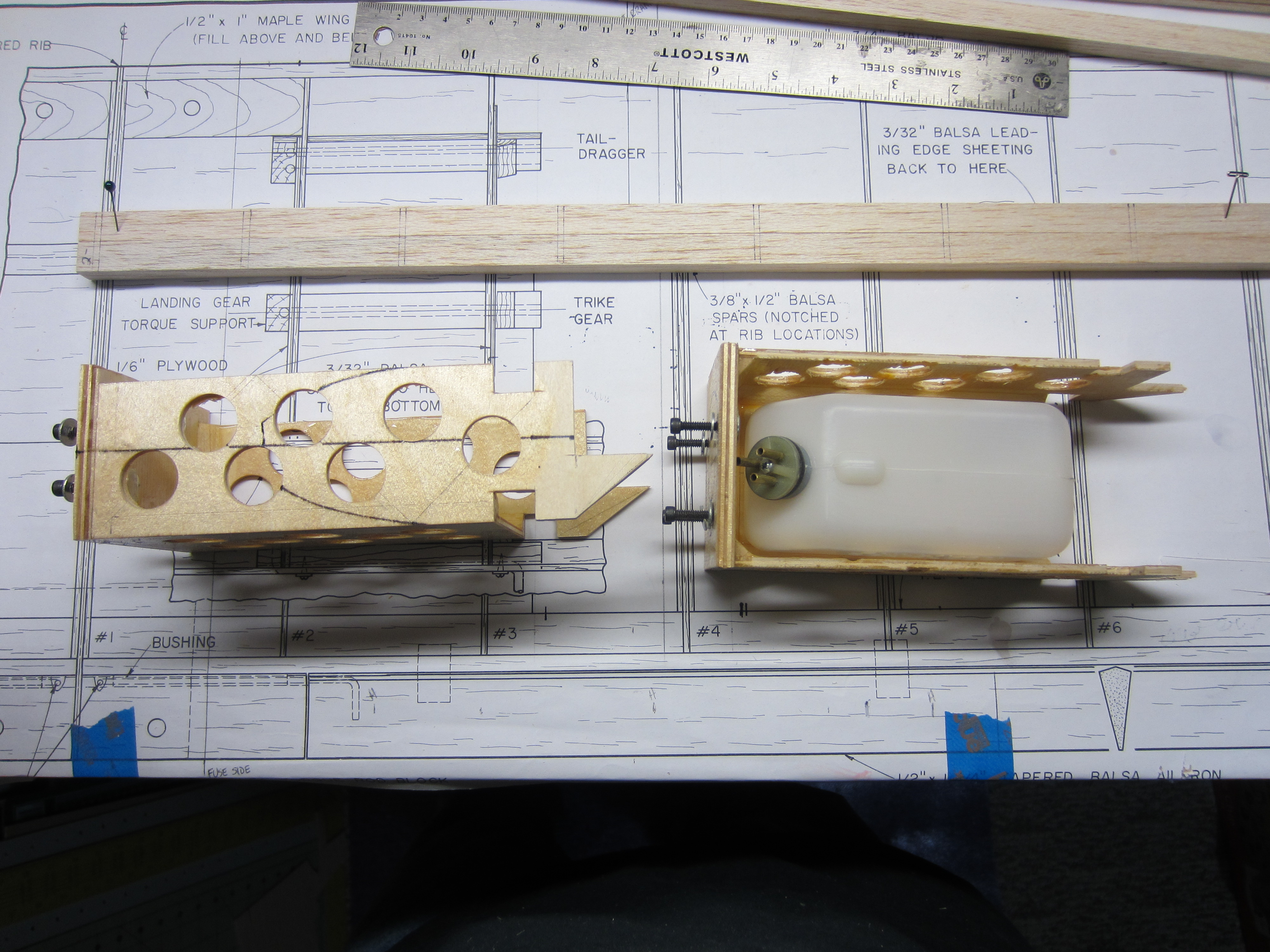
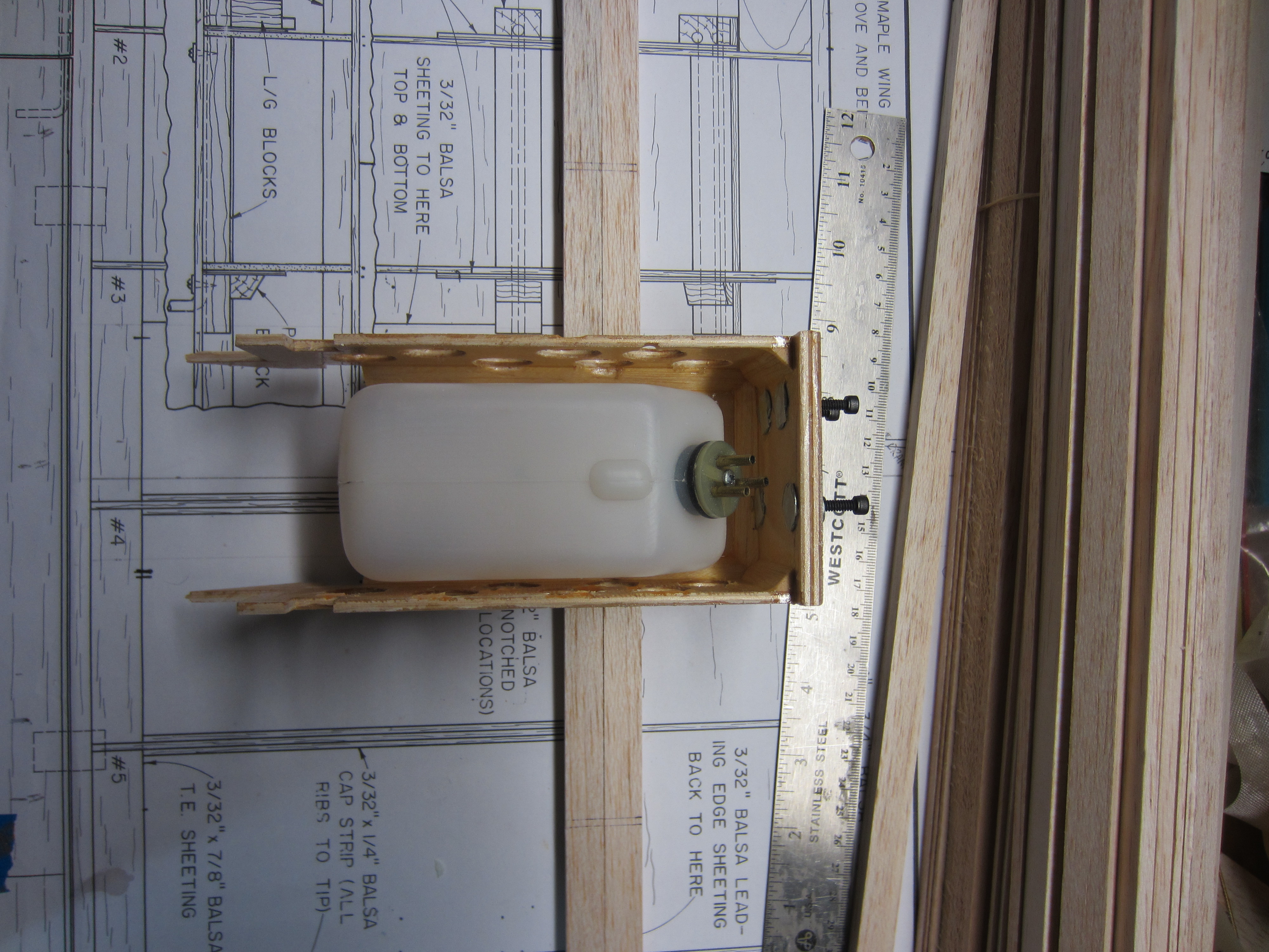
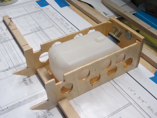
One idea I toyed with was using flask-shaped bottles as fuel tanks. These could be buried in the wing structure, and would make for a much smaller nacelle, with the firewall at the leading edge (or even behind it). The WeldBond bottle on my bench was ideal, 8 oz., and made of HDPE. I saw some problems with arranging the fuel and fill lines, so decided to go with more conventional nacelles. Maybe on my next build...
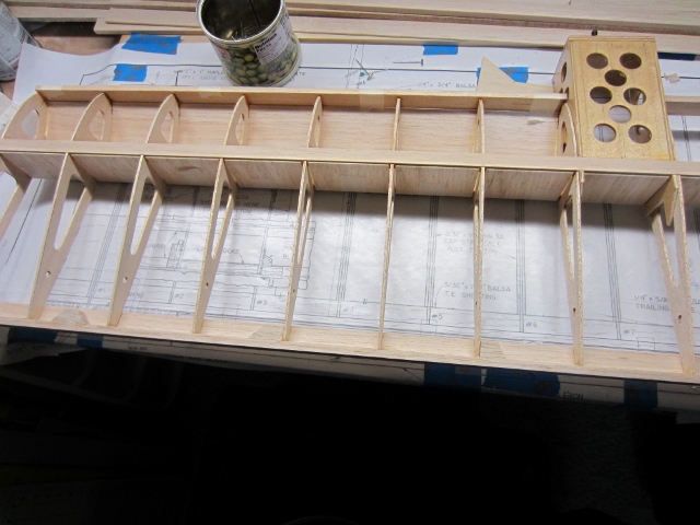
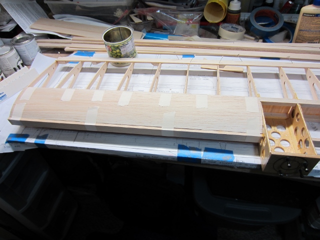
The leading and trailing edges are all sheeted now, just have to install mounts for the flap and throttle servos. I'm going to build slotted flaps, using control horns to get the slotted effect, and power them with standard Futaba 3004 servos in each wing. The throttles will be controlled by Futaba 3115 servos with flex cables running through the nacelles.
I'll be using Robart hinge points for the ailerons , so I added balsa blocks at the trailer edge for extra support. Both the flaps and ailerons will have their servos side-mounted in hatches on the underside of the wing.
I will be fairing in the nacelles using 1/4" balsa sheet, with a removable hatch in the top for access to the tank and the throttle servo.

 01-25-2014 | 11:00 AM
#11
Thread Starter
My Feedback: (11)
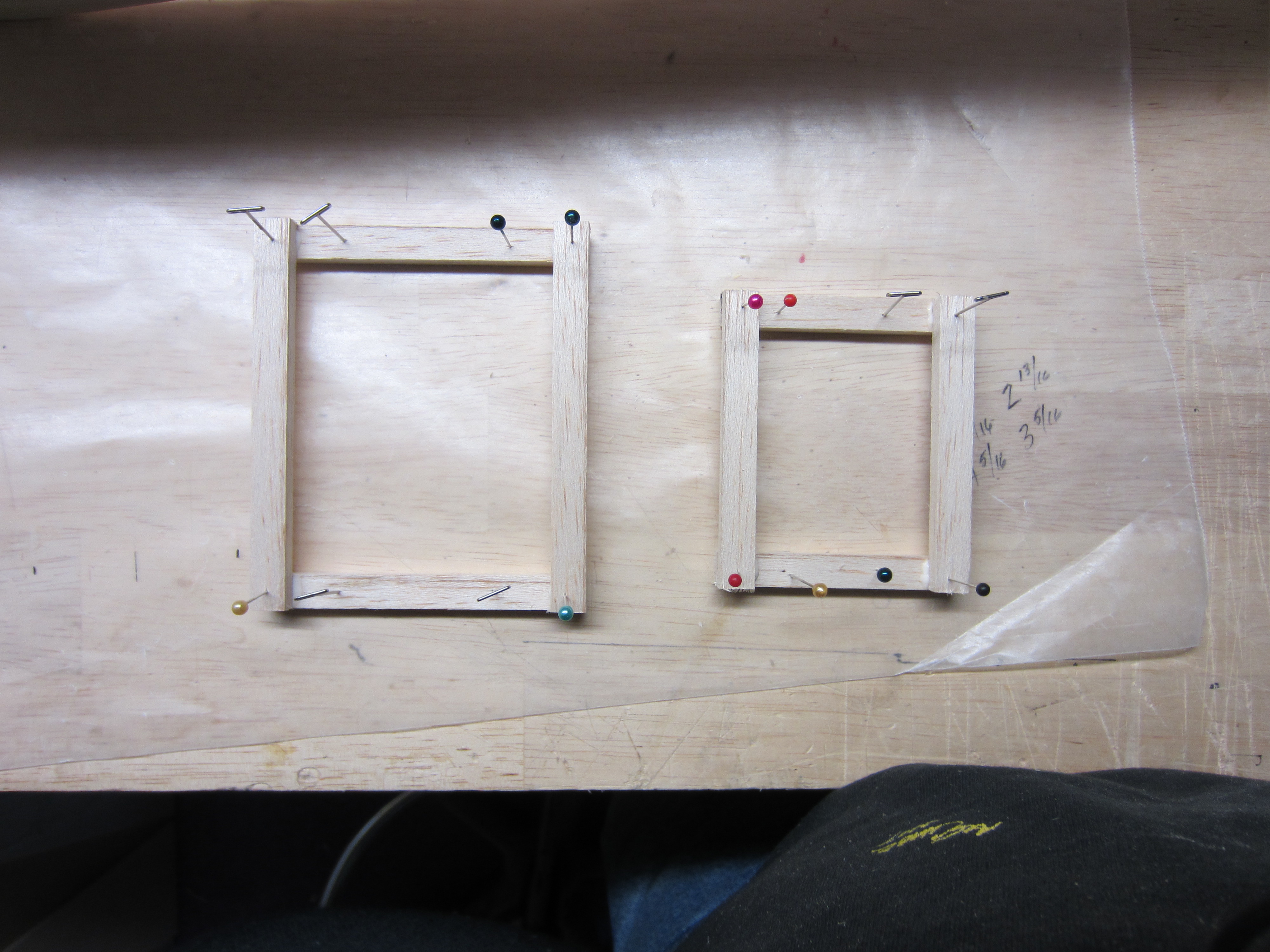
Well, it's been almost 3 weeks now. I took a bit of time off from the project, and only picked it back up a couple of days ago. First off, I built a mock-up of the flap system I plan to use. This is a slotted flap arrangement, using control horns for hinges.
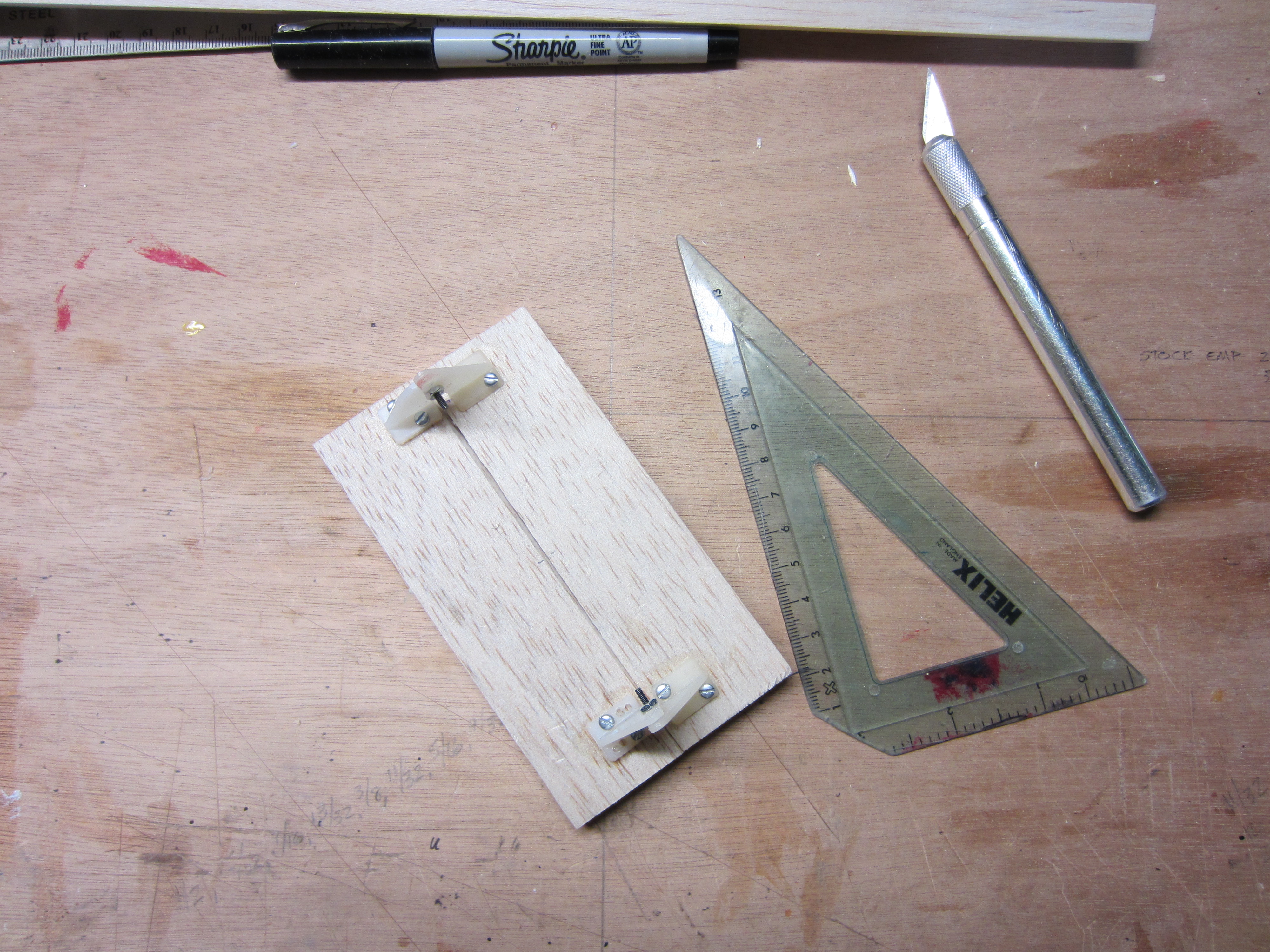
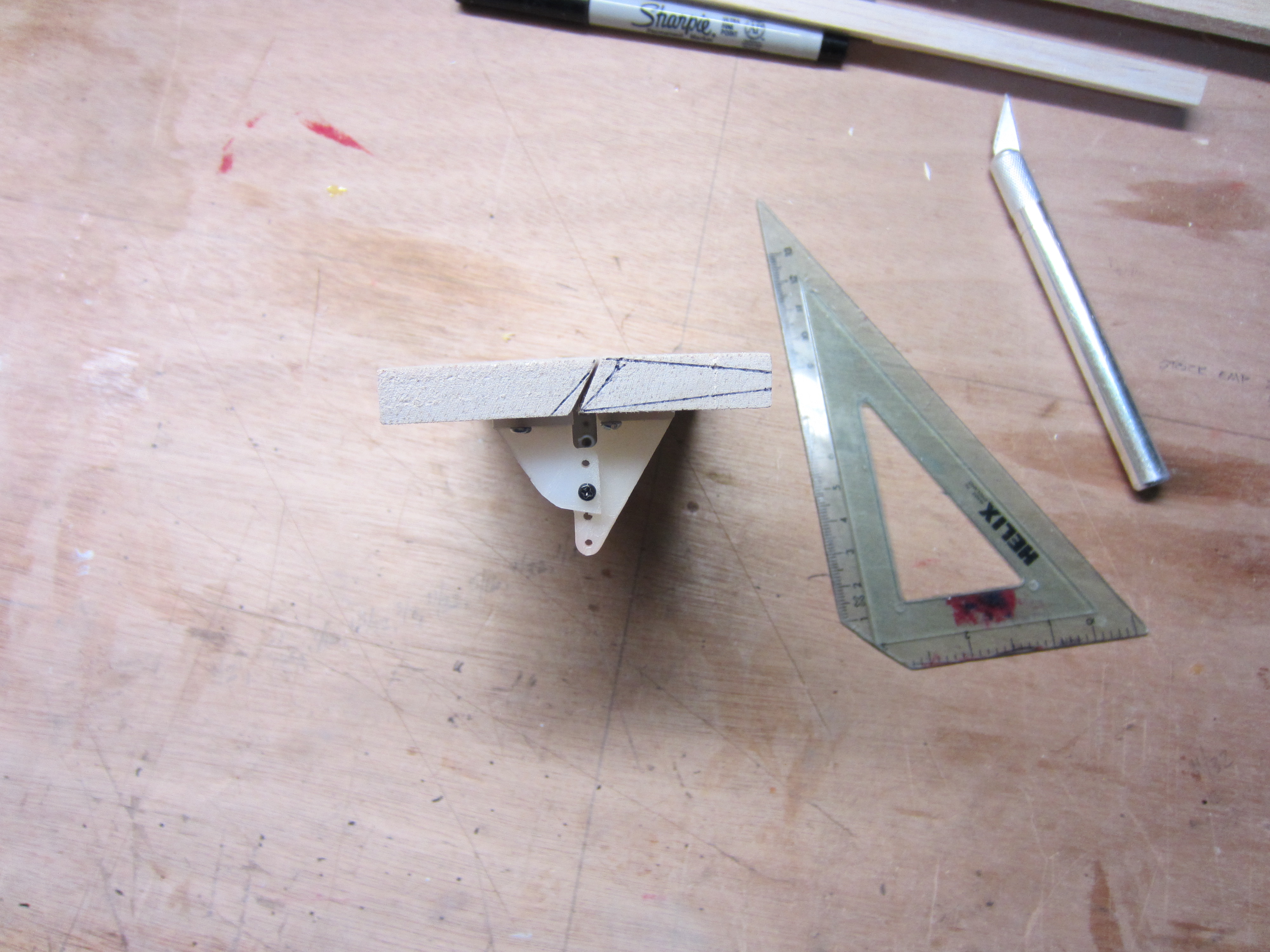
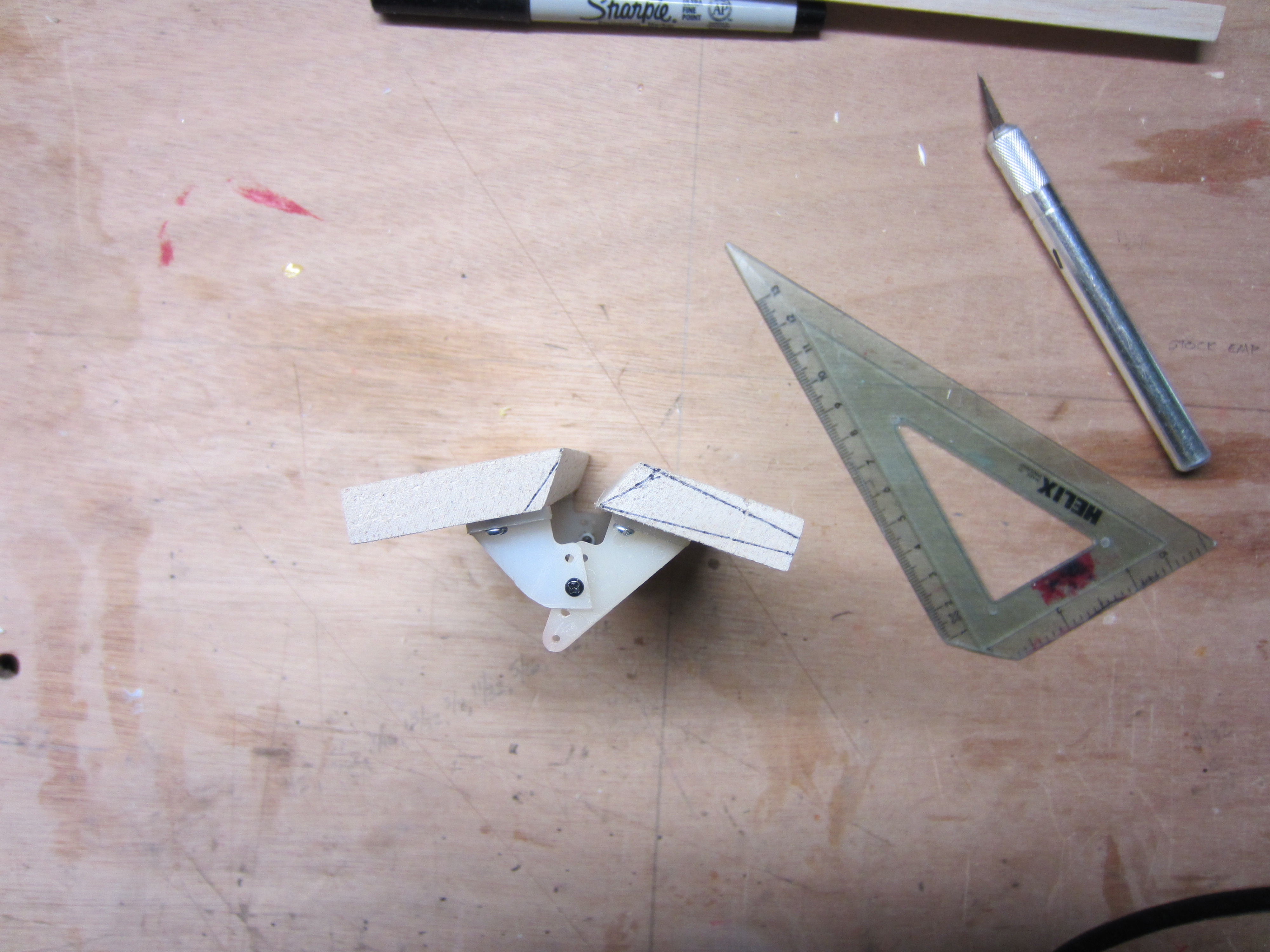
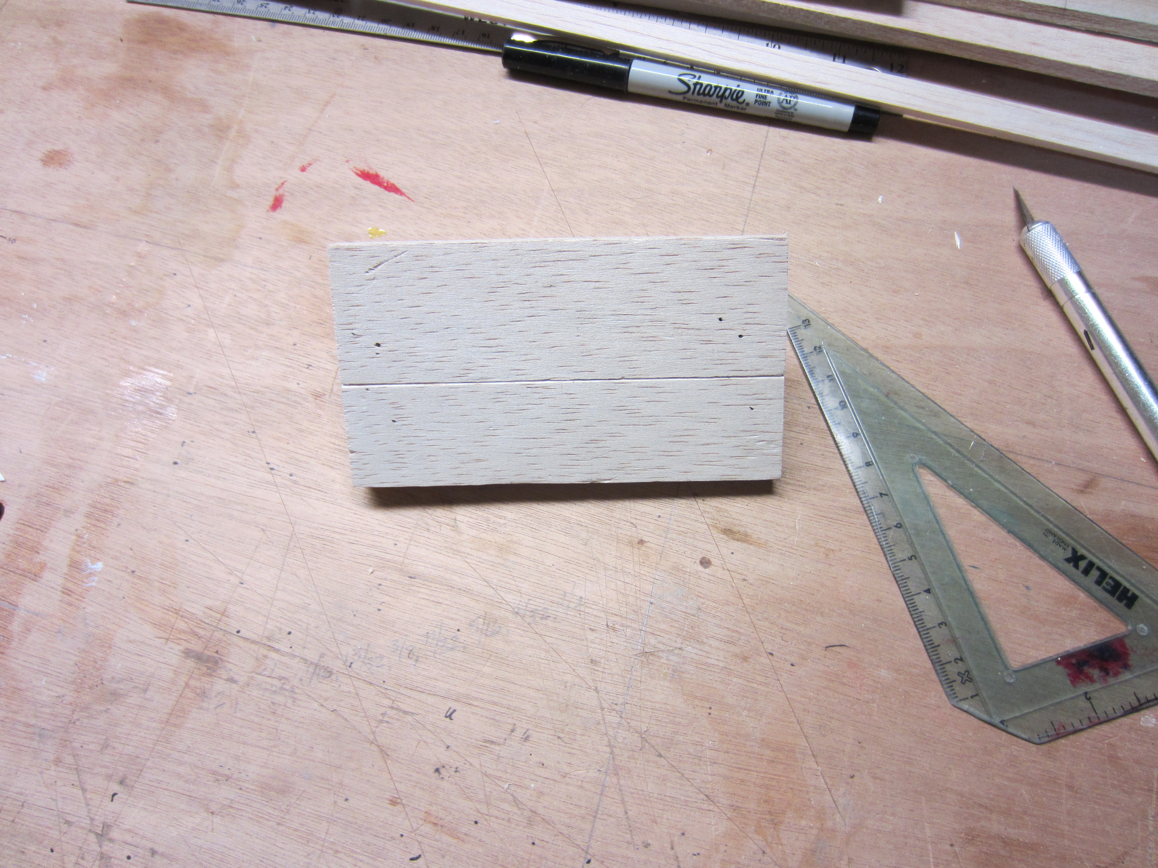
This should work pretty well! It'll be nearly gapless, both top and bottom. All of the horns but one will be shortened, and the one that will remain long will be connected to the servo for actuation.
This should work pretty well! It'll be nearly gapless, both top and bottom. All of the horns but one will be shortened, and the one that will remain long will be connected to the servo for actuation.
01-25-2014 | 11:10 AM
#12
Thread Starter
My Feedback: (11)
Most of this stuff is new to me, so a big shout out to all the people who've posted their ideas!
The servos for the ailerons will be mounted to plates that get screwed into wells in the wing, leaving just the servo arm protruding. This will also give a straighter shot for the control linkage, no weird side-to-side motions.
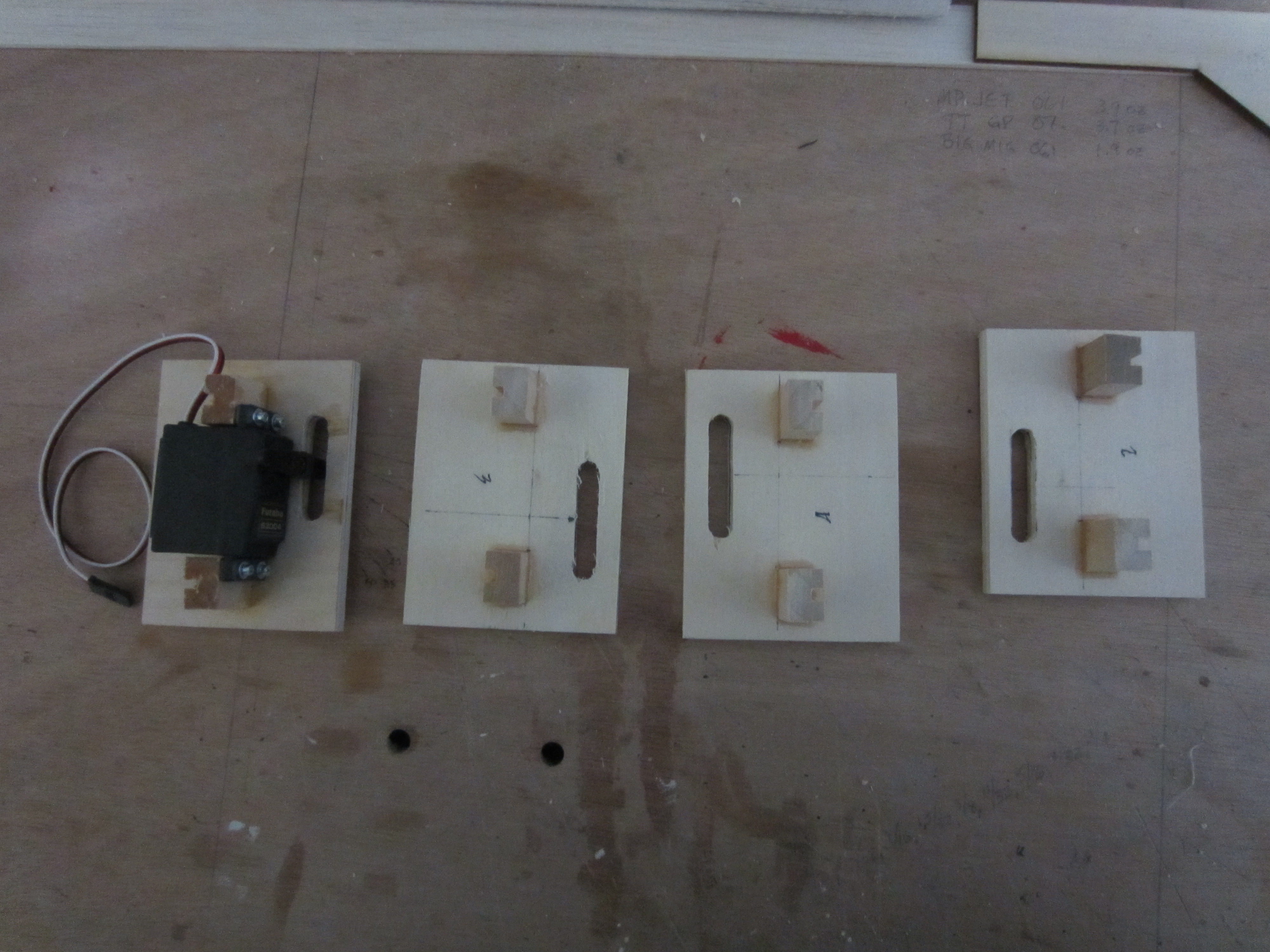
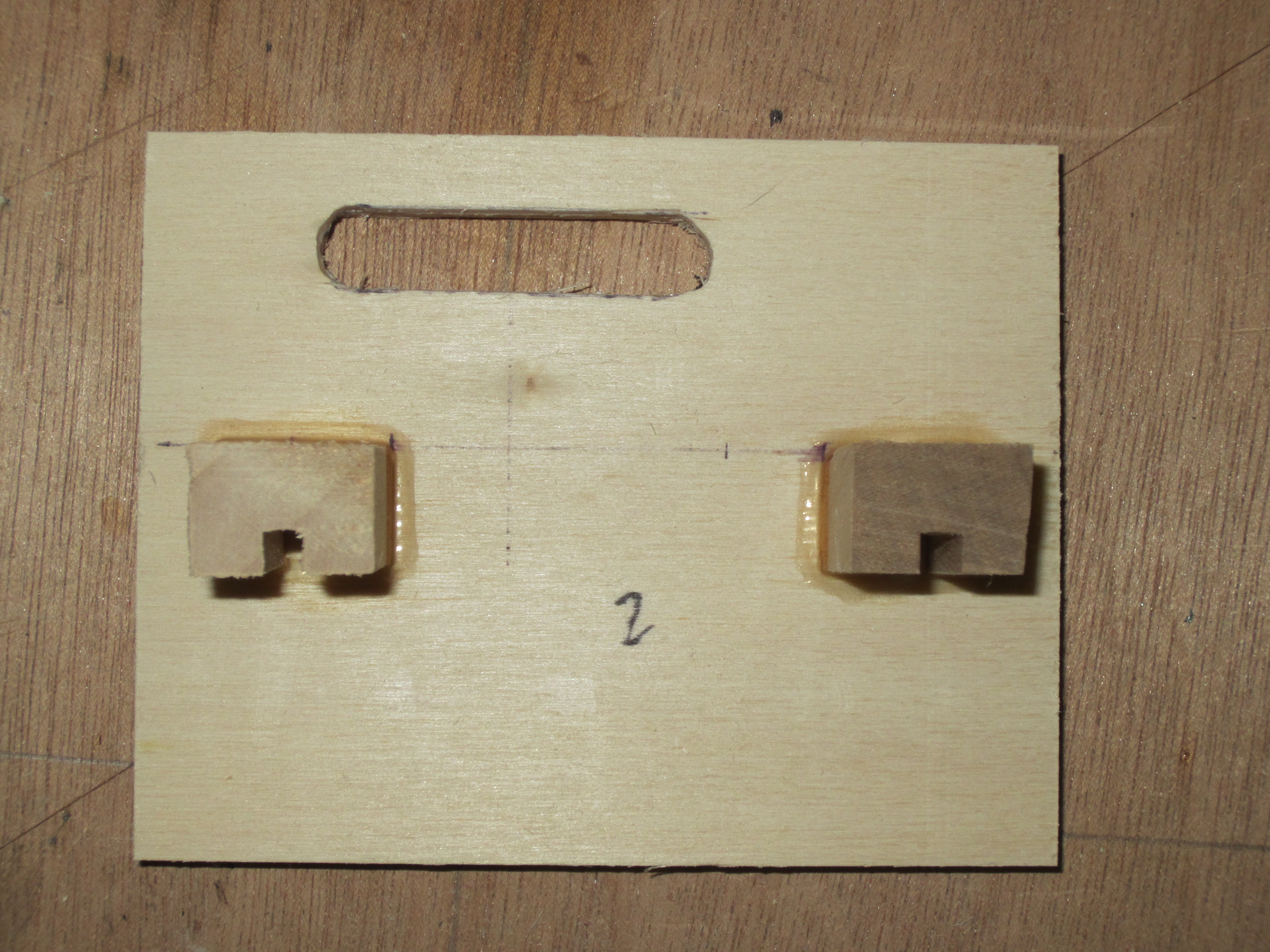
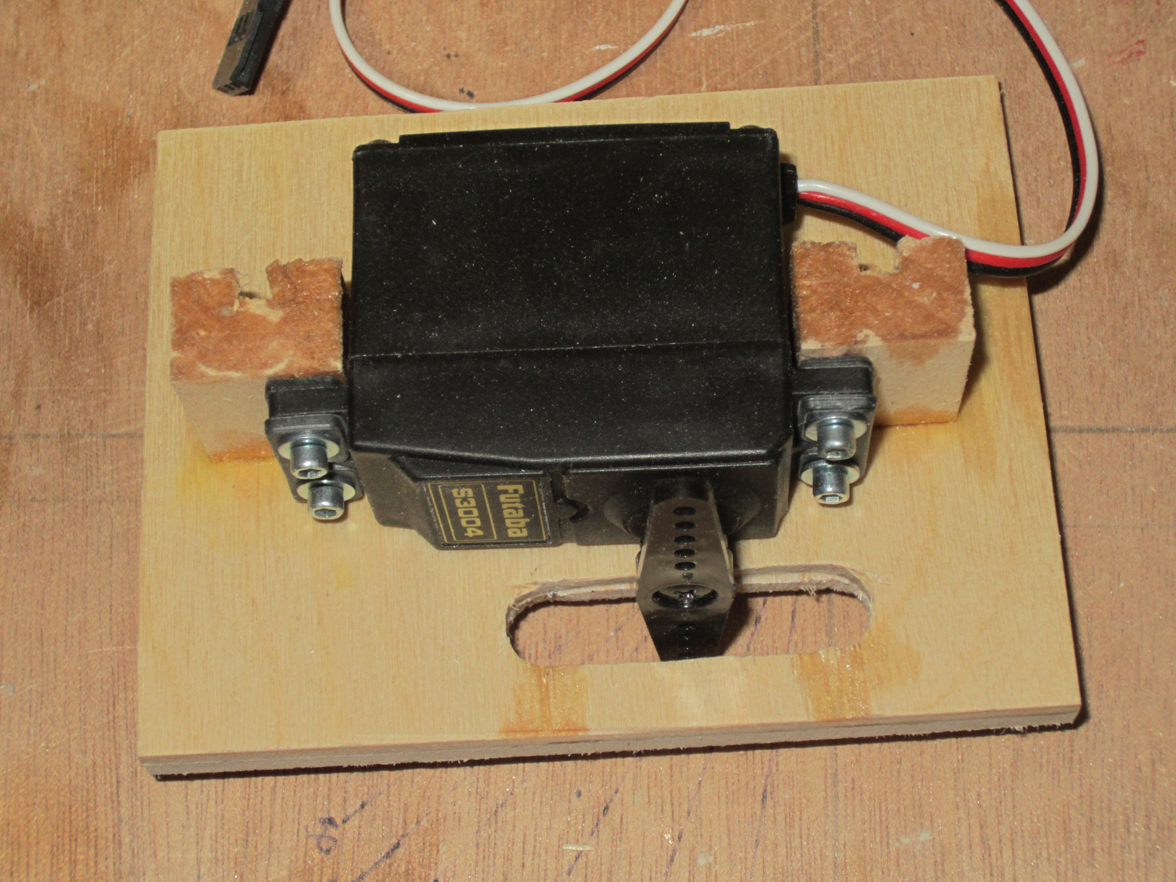
The servos for the ailerons will be mounted to plates that get screwed into wells in the wing, leaving just the servo arm protruding. This will also give a straighter shot for the control linkage, no weird side-to-side motions.
01-25-2014 | 11:46 AM
#14
Thread Starter
My Feedback: (11)
Now to the really fun part, the fuselage! Since this plane will be a high winger, I thought about just flipping over the sides that came with the kit, but I figured I needed a bit more fuselage length, so I found some 48" pieces of 3/16" balsa, and used every bit of that length. The kit pieces are only 39 1/2" long. This should help with stability and control authority.
I started off by transferring the kit fuselage outlines onto my bigger balsa sheets, then cut them out. I used 1/4" birch plywood for the floor and bulkheads, and added the blind nuts for the landing gear mounting. Next, I added the kit style formers to the fuselage.
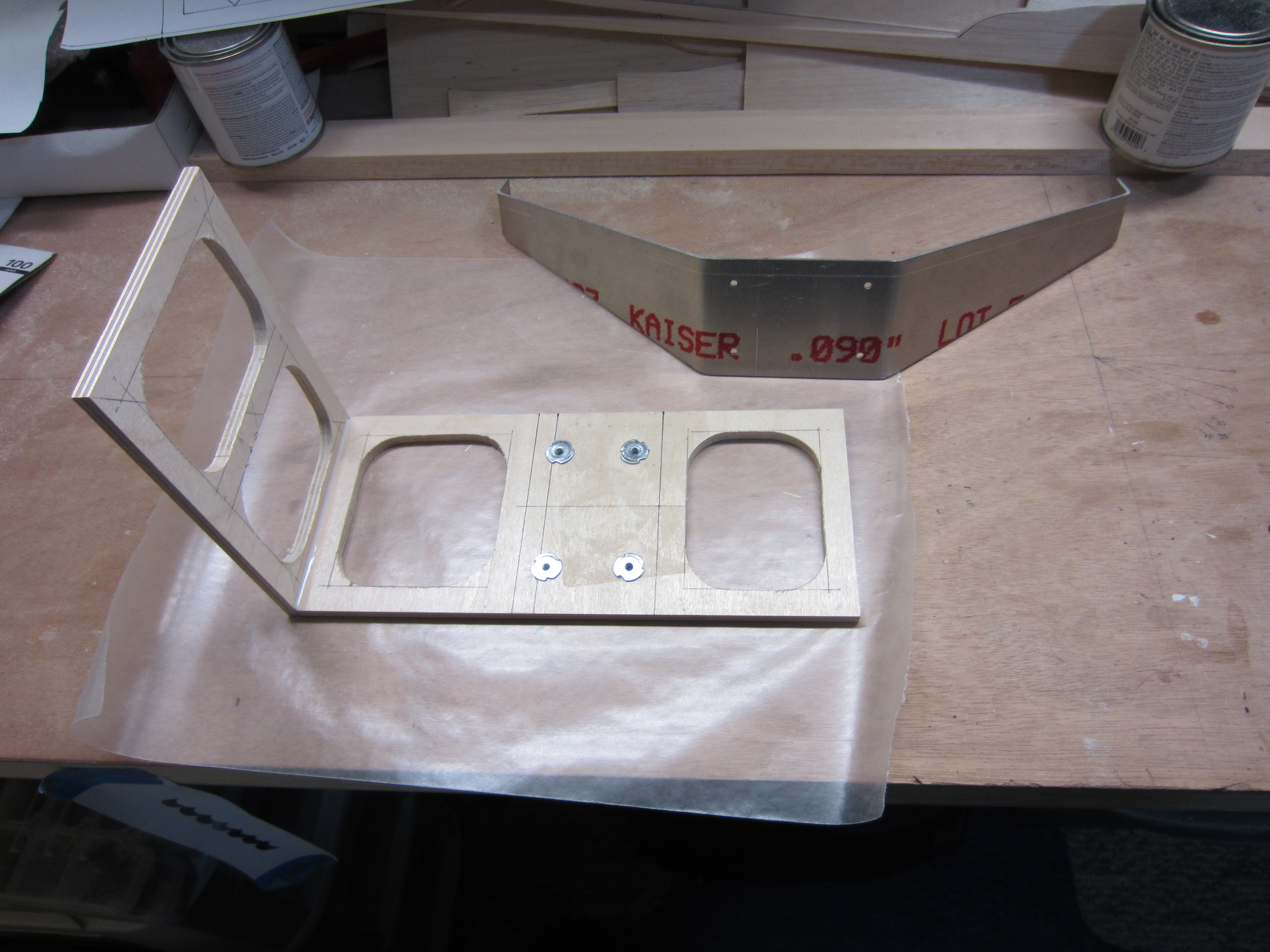
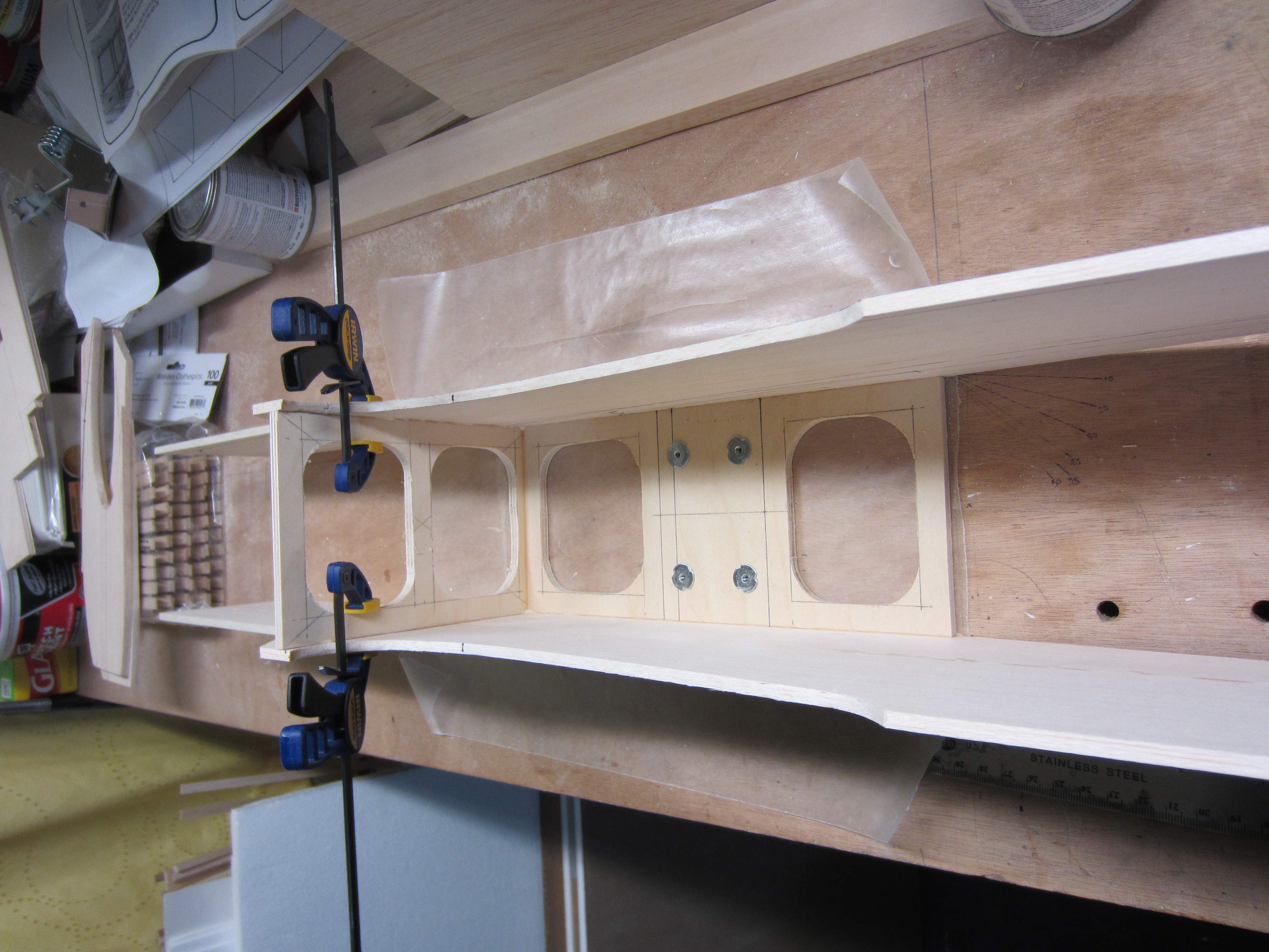
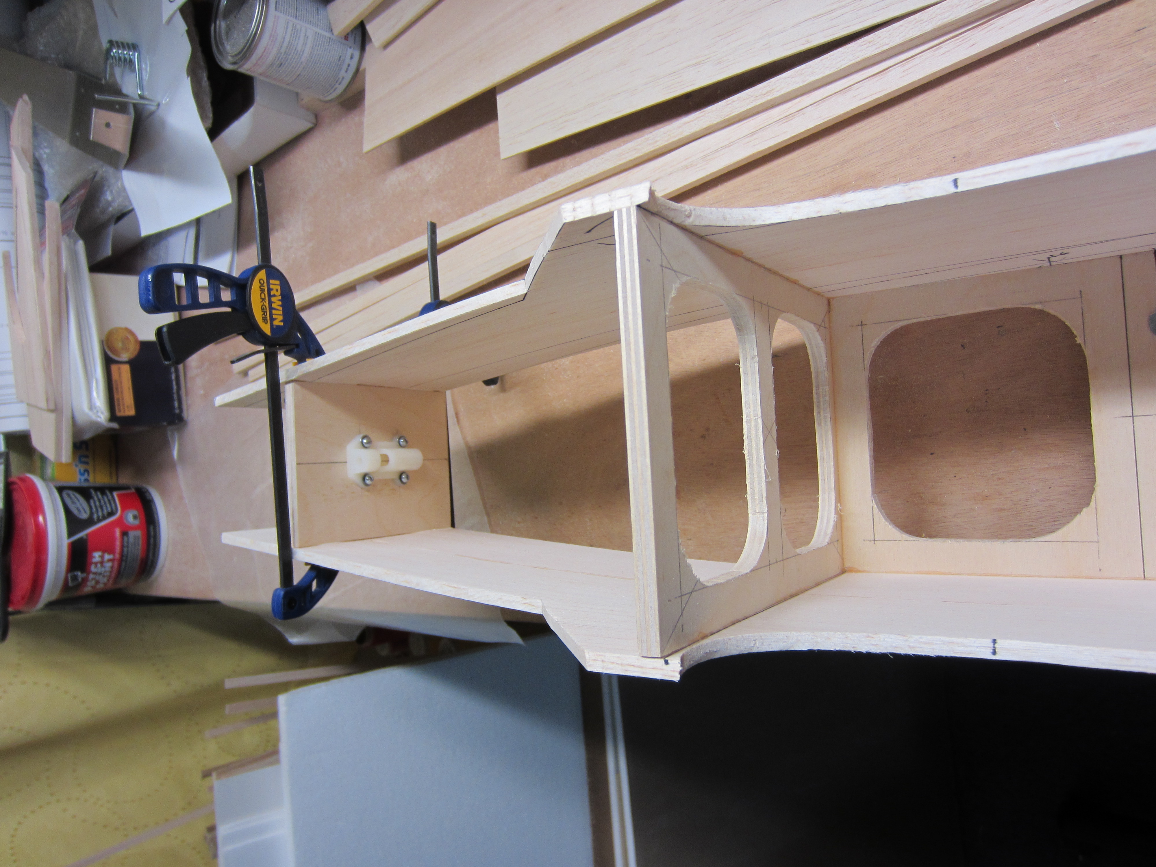
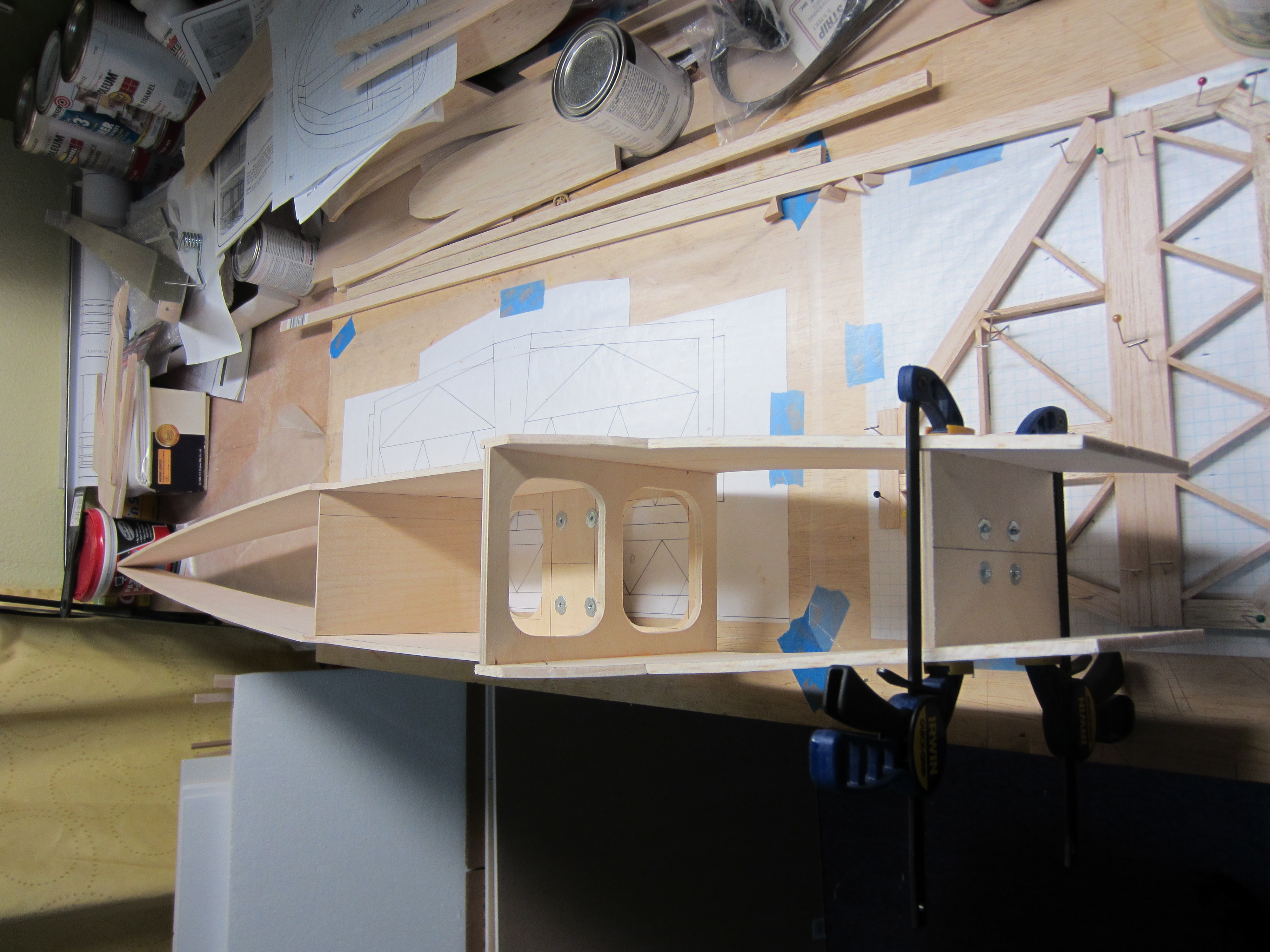
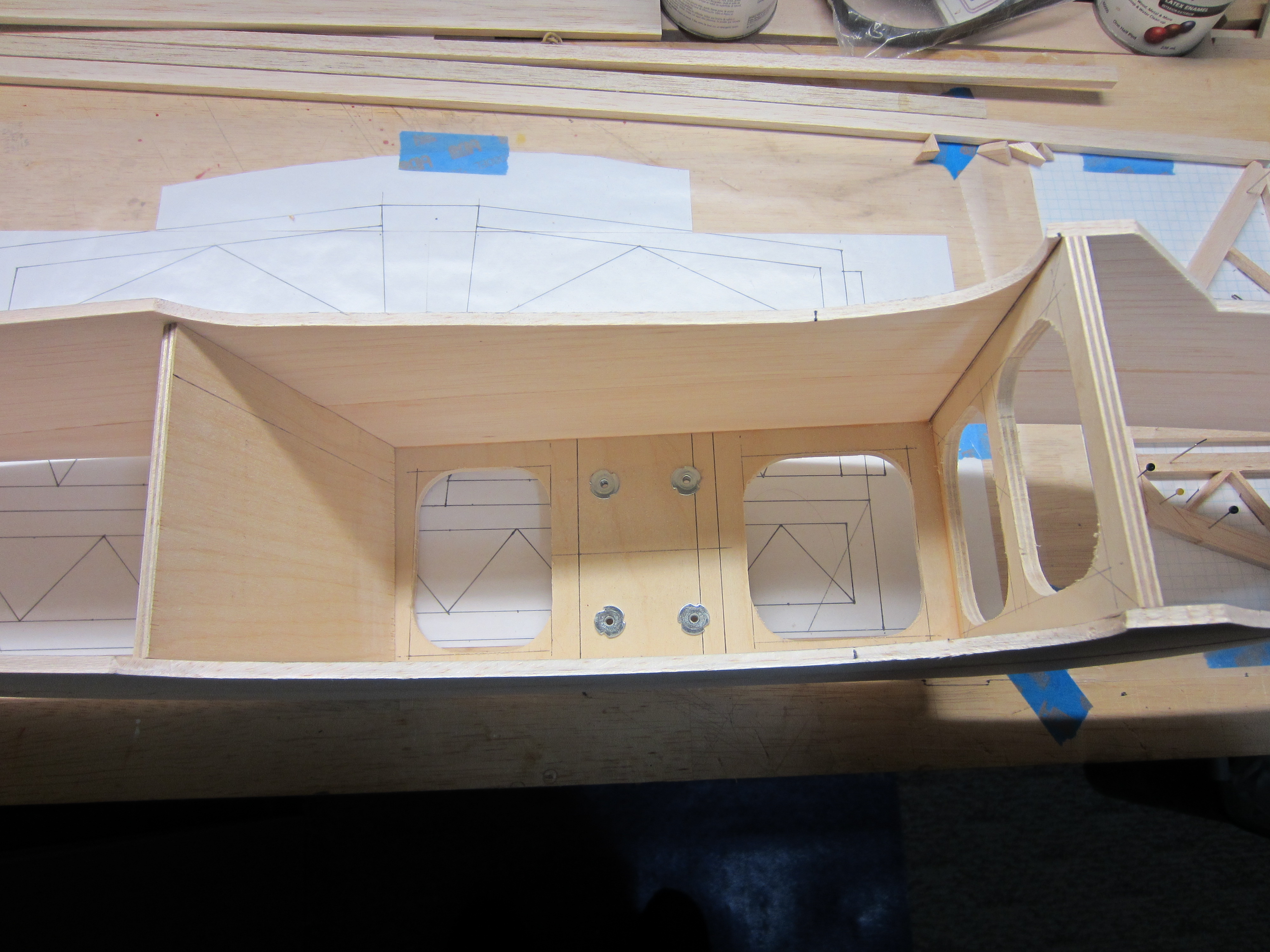
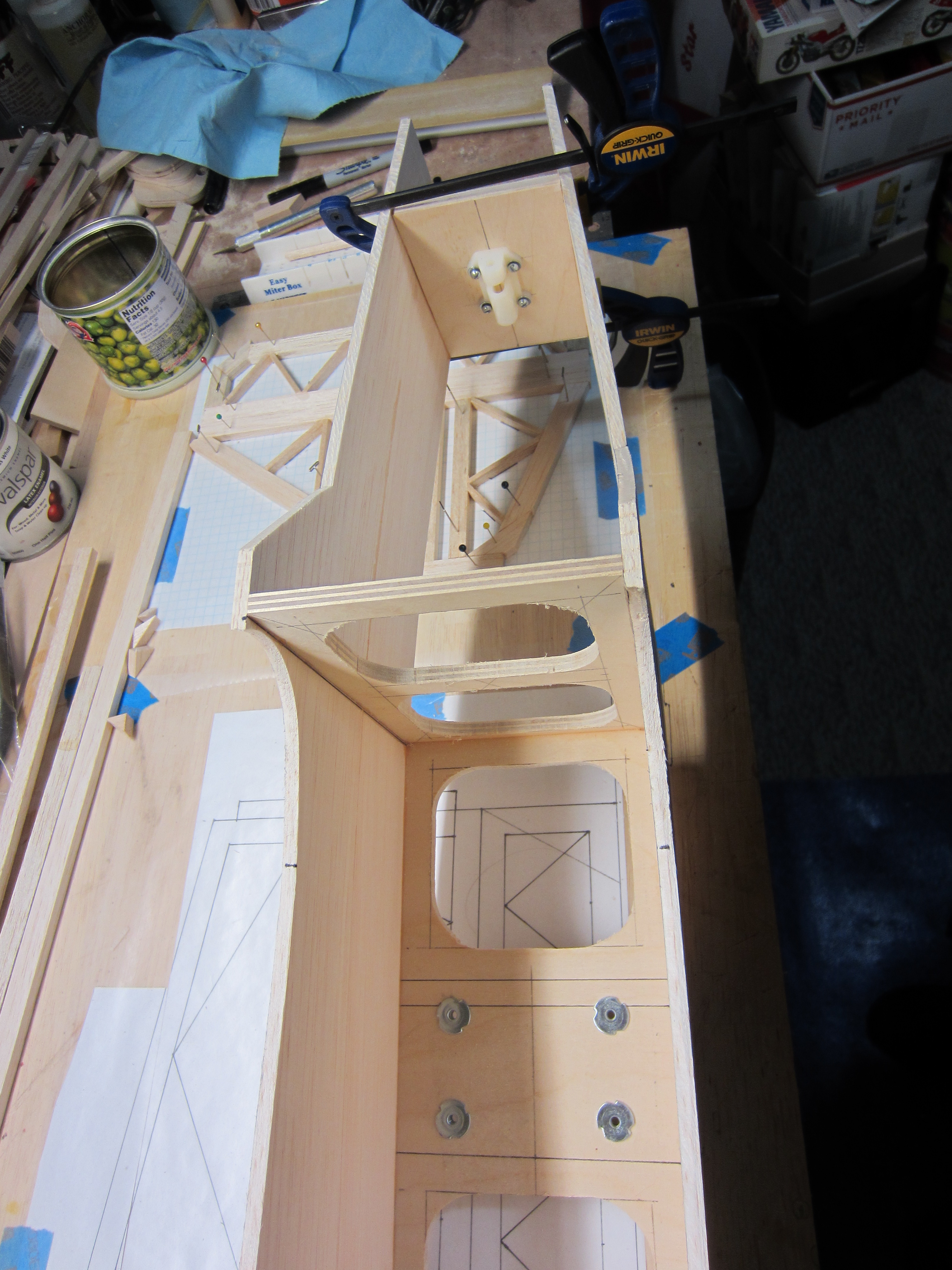
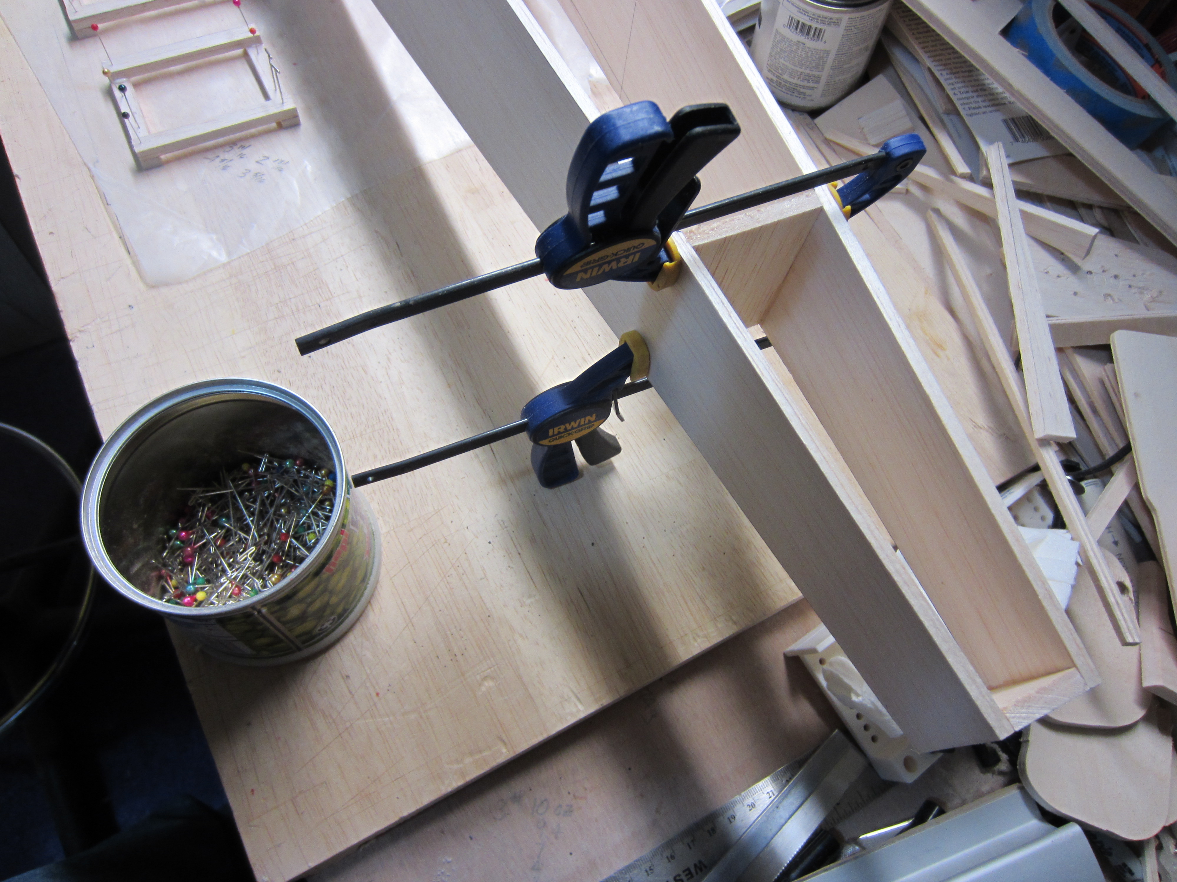
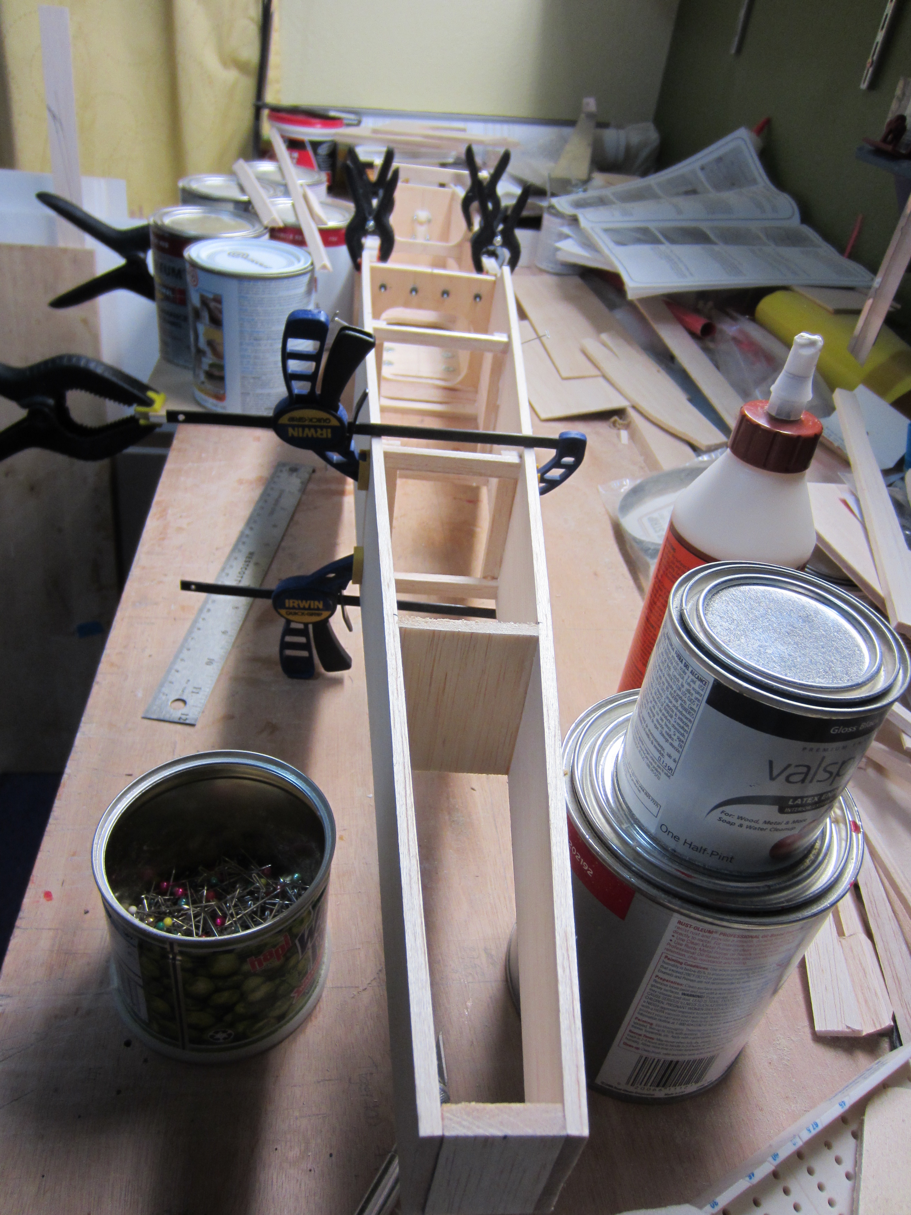

I started off by transferring the kit fuselage outlines onto my bigger balsa sheets, then cut them out. I used 1/4" birch plywood for the floor and bulkheads, and added the blind nuts for the landing gear mounting. Next, I added the kit style formers to the fuselage.
01-25-2014 | 11:54 AM
#15
Thread Starter
My Feedback: (11)
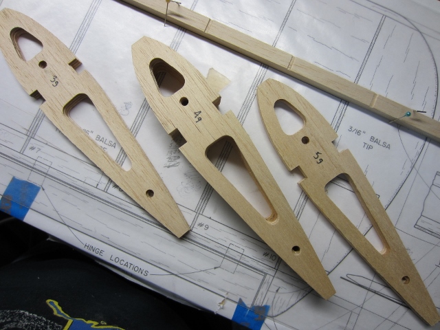
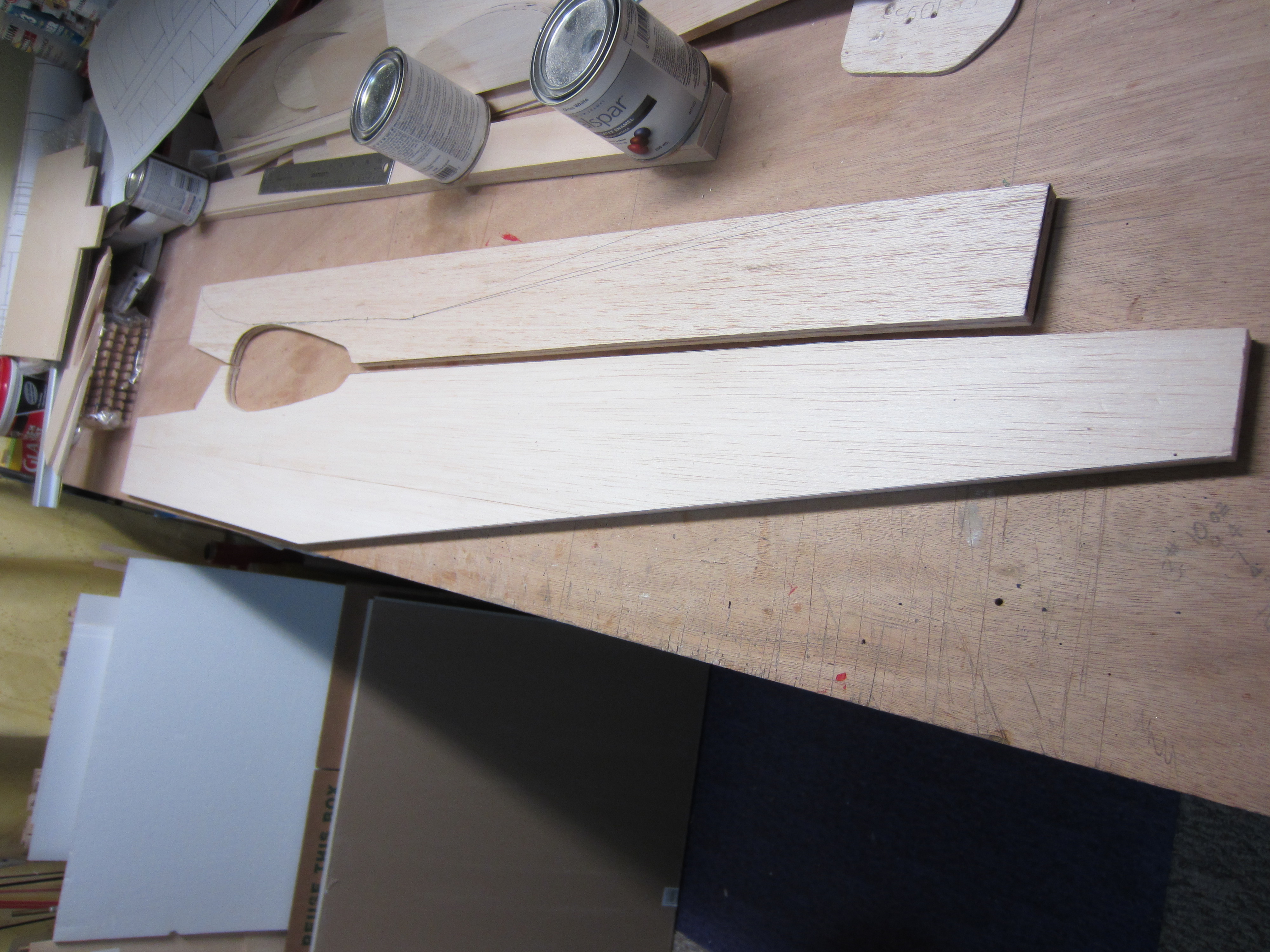
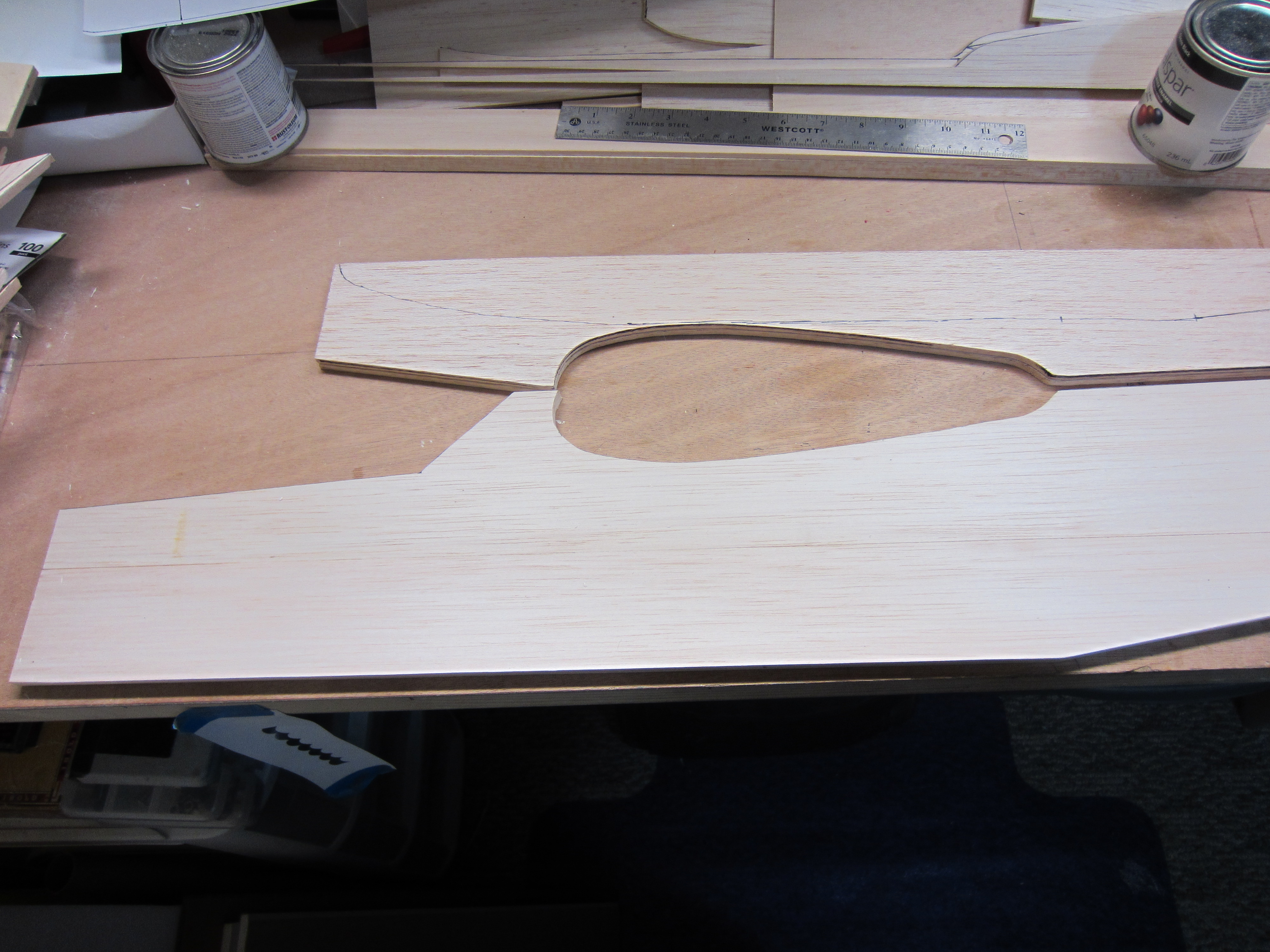
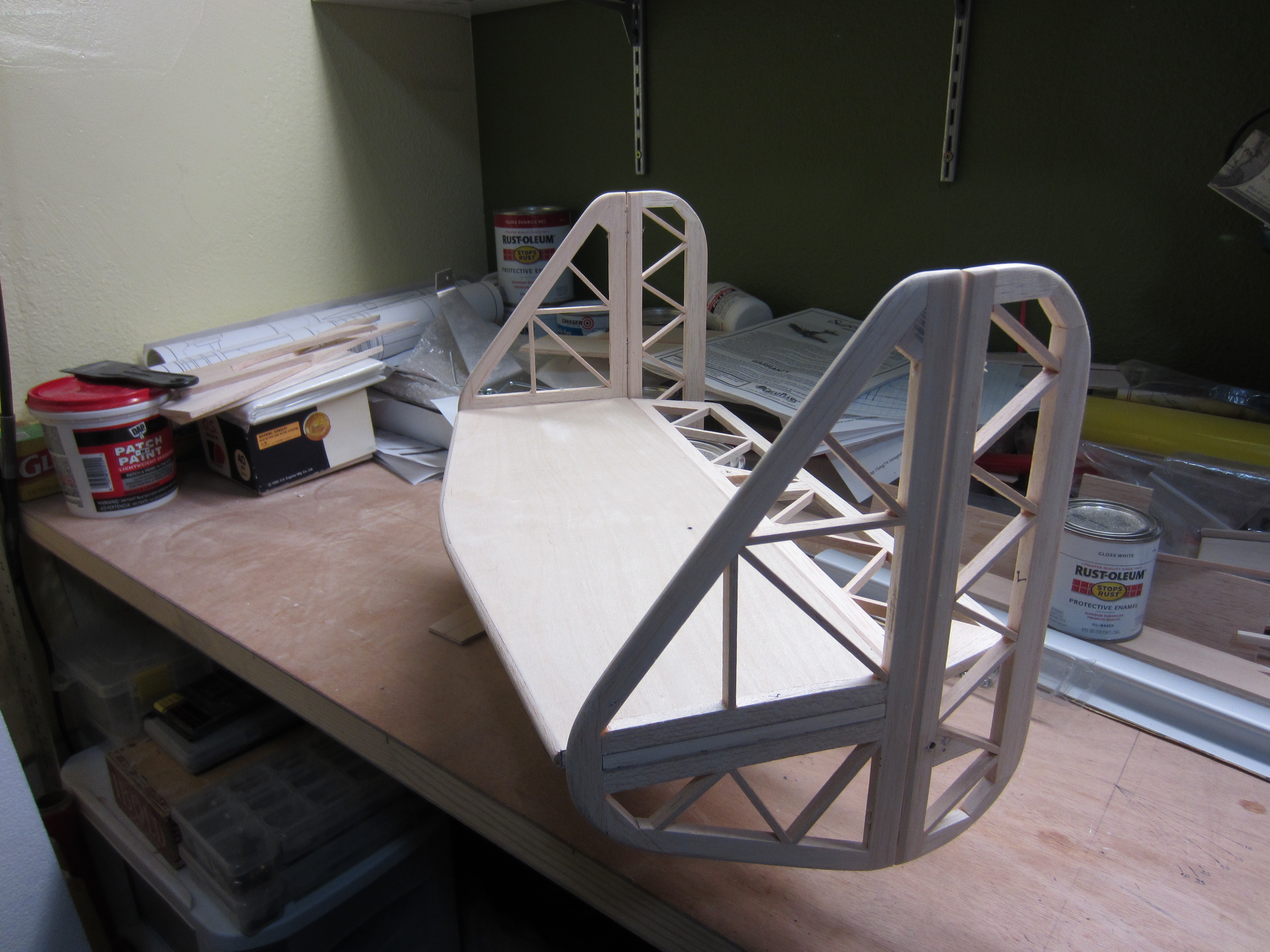
Now it's time for some tail feathers.
I spent a lot of time researching the sizes of all the tail surfaces, and found lots of helpful information in the forum. Here's my designs. The horizontal stabilizer has tabs to fit into the vertical stabilizers. I'm going to laminate 1/32 plywood on both top and bottom of the horizontal stabilizer to add some rigidity, and to help with the mounting of the vertical units.
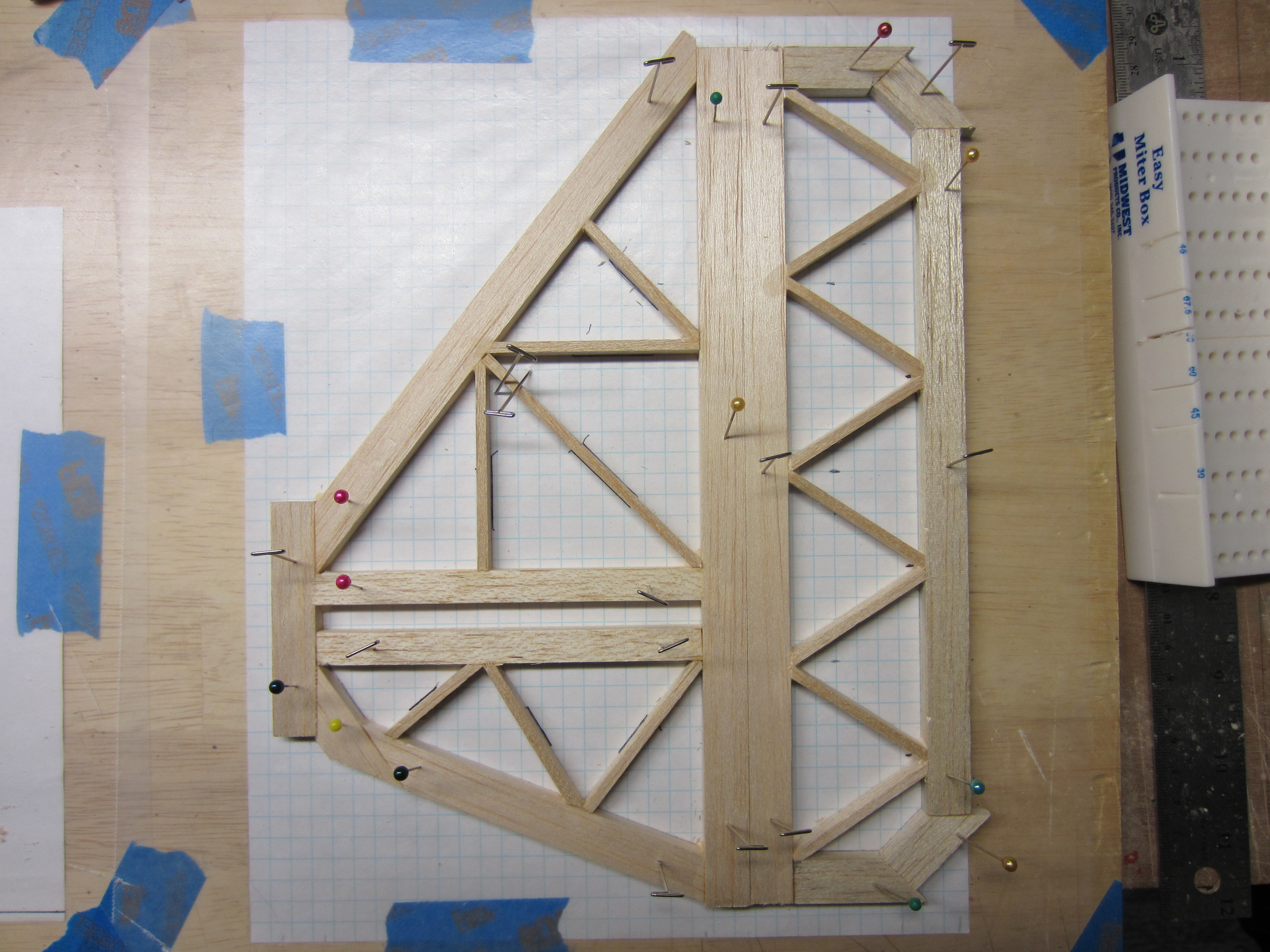
I spent a lot of time researching the sizes of all the tail surfaces, and found lots of helpful information in the forum. Here's my designs. The horizontal stabilizer has tabs to fit into the vertical stabilizers. I'm going to laminate 1/32 plywood on both top and bottom of the horizontal stabilizer to add some rigidity, and to help with the mounting of the vertical units.
02-05-2014 | 07:18 PM
#16
Thread Starter
My Feedback: (11)
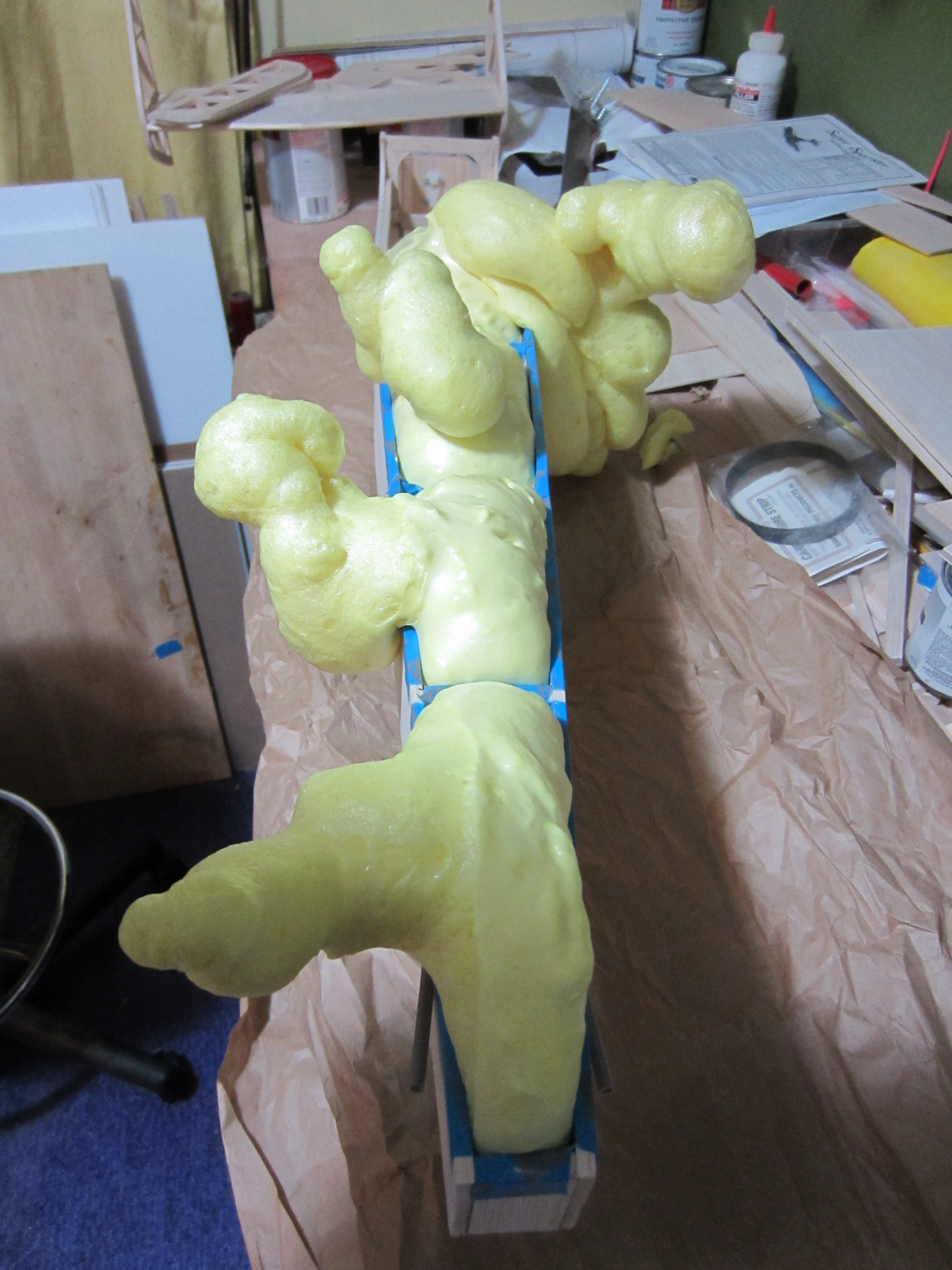
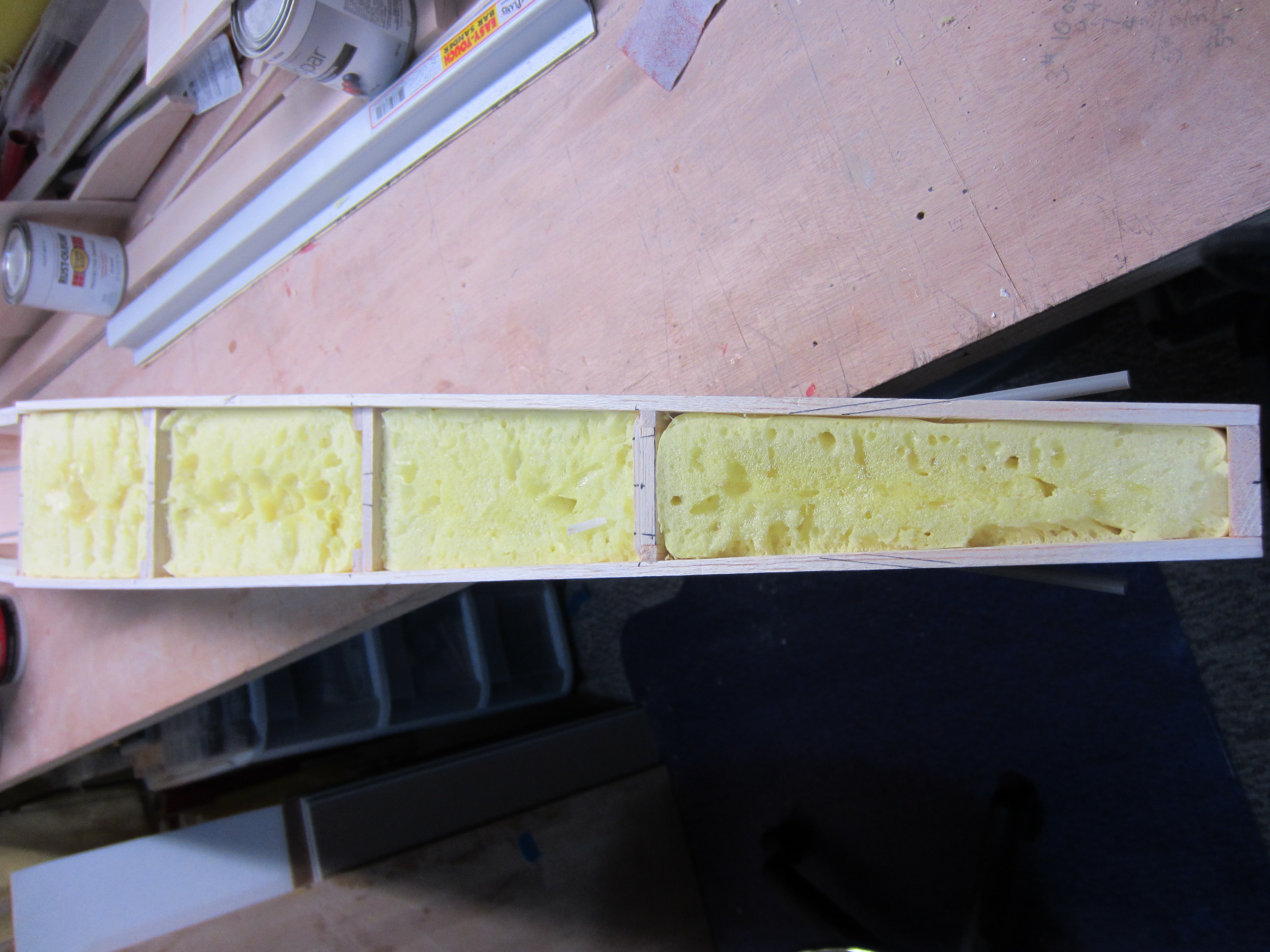
With all this heavy tail structure going on the rear of the fuselage, I figure I'll need all the stiffness I can get! I saw this idea in these forums a week or so, and it made sense to me so I figured I'd give it a try. The idea is to fill the fuselage with spray foam, and I just happened to have a partial can of it the closet. This is the formula made for doors and windows, so it's the minimally expanding type. The instructions say to fill the spaces only half full. I masked off all the parts I didn't want foam on, then filled the spaces half full, and waited. After a few minutes, I was seeing very little expansion, so I filled it up to 3/4 full, then waited some more. Talk about delayed reactions! About an hour later, the foam finally stopped expanding! The next day, I was able to trim the foam with a bread knife, so it looked a bit more reasonable. The fuselage shouldn't do much twisting now.
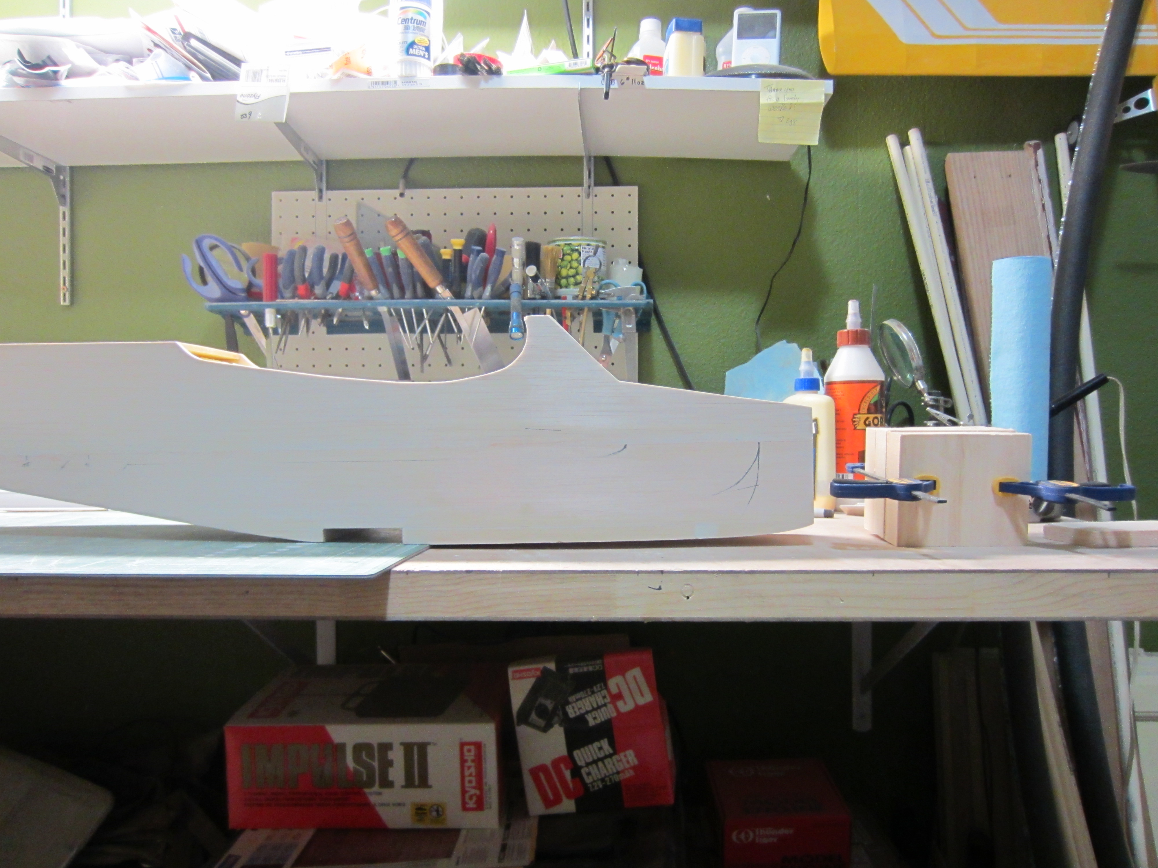
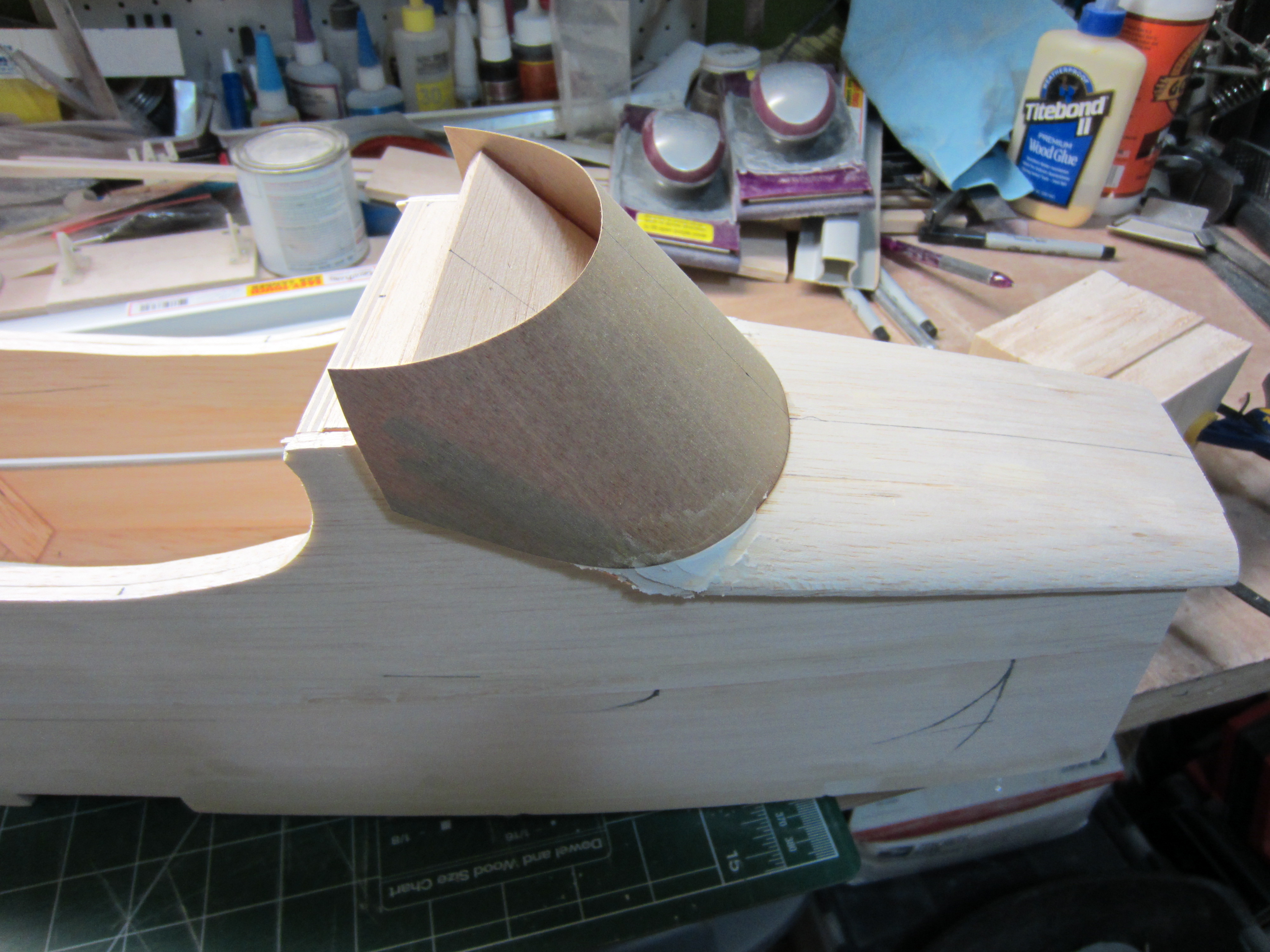
I then added some 1/2" sheet to the bottom to improve the look of the fuselage, then started building the front hatch. I may need to mount the servos for the rudder and elevator in the nose to get the plane to balance, so a removable hatch will be required. I decided to add the windshield to the hatch, and built it out of 1/32" plywood. A little black paint and it'll look nice.
I then added some 1/2" sheet to the bottom to improve the look of the fuselage, then started building the front hatch. I may need to mount the servos for the rudder and elevator in the nose to get the plane to balance, so a removable hatch will be required. I decided to add the windshield to the hatch, and built it out of 1/32" plywood. A little black paint and it'll look nice.
02-05-2014 | 07:39 PM
#17
Thread Starter
My Feedback: (11)
After framing up the tail surfaces, I laminated the horizontal stabilizer with 1/32" plywood, top and bottom. This added a bit of weight, but it sure strengthened the structure, and that was needed. It also reinforces the tabs on the ends where the vertical stabilizers fit. I was a bit worried about the strength of that joint, but I think its good now.
I thought I had a simple control mechanism worked out for the twin rudders, but couldn't seem to get the geometry right, so I had to make it complicated. Three bellcranks later, I got it all worked out. It's a bit Rube Goldberg-ish, but with a bit of Loctite on all the screw, it should hold up well.
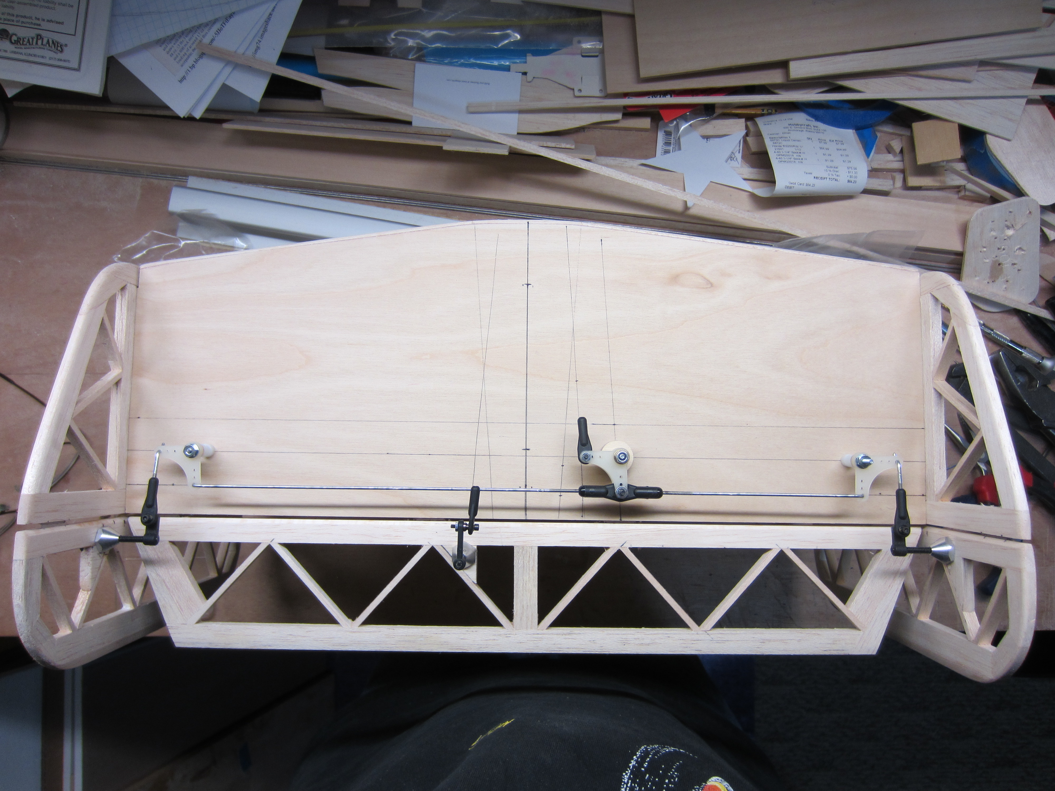
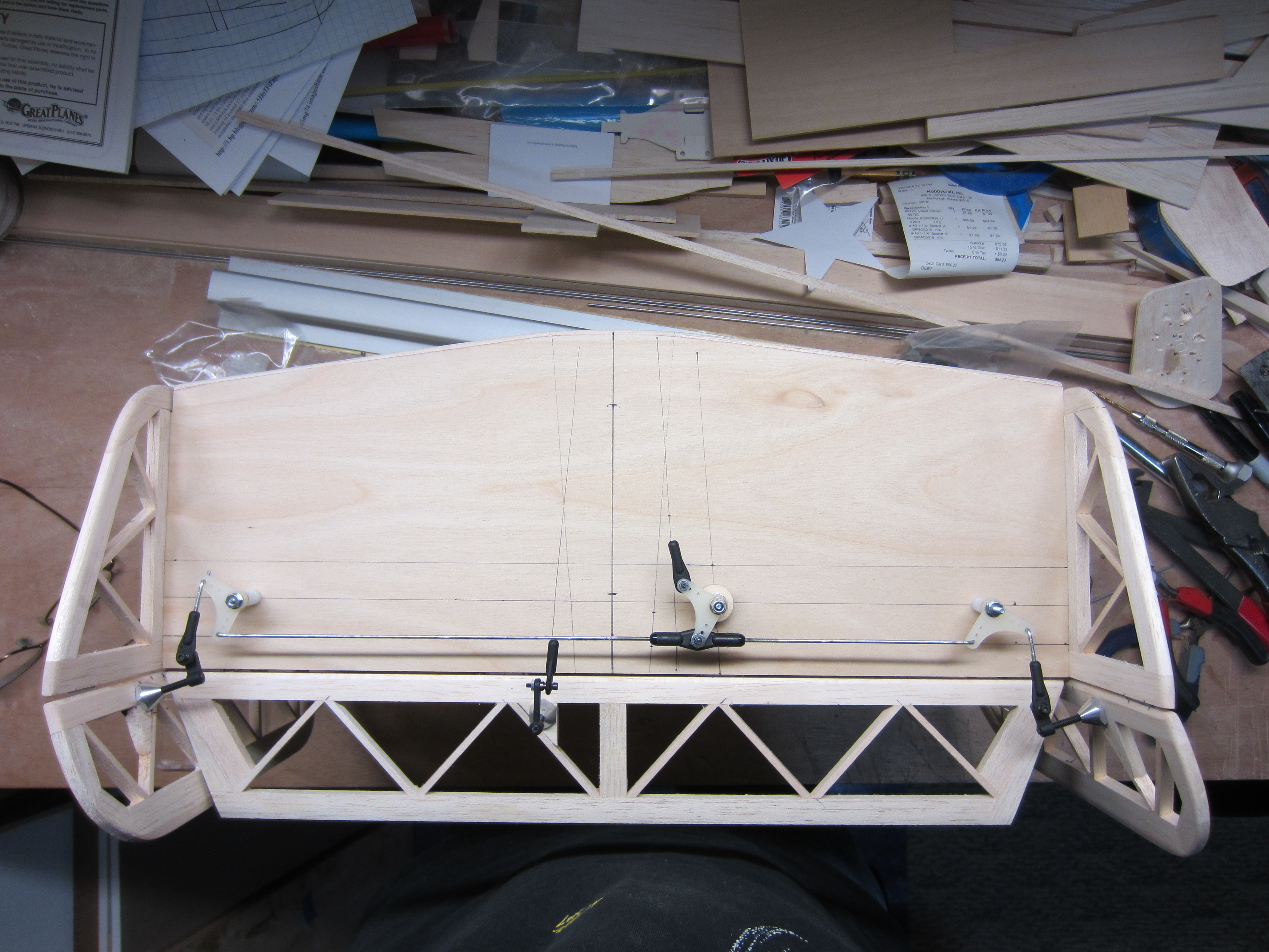
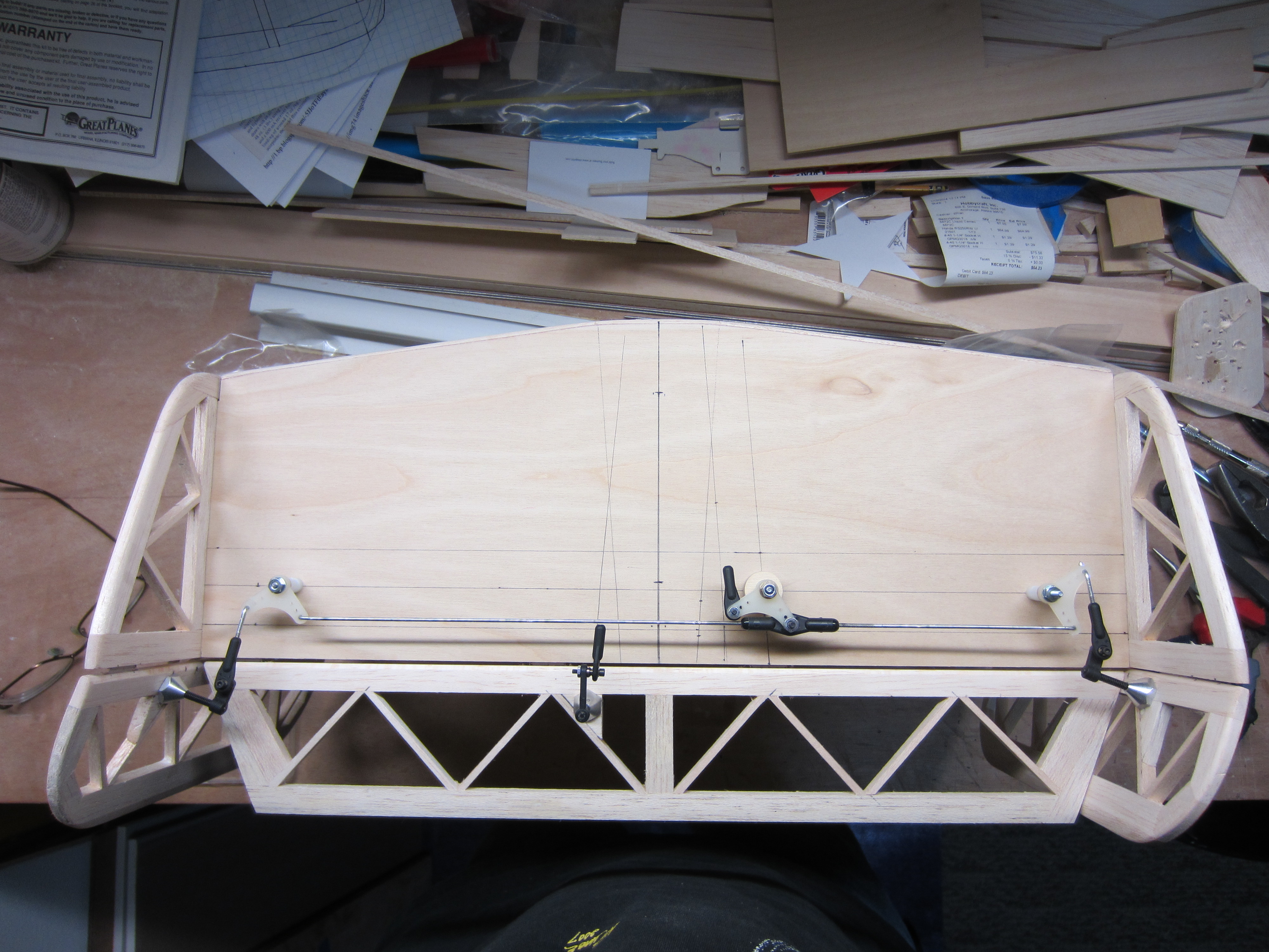
I thought I had a simple control mechanism worked out for the twin rudders, but couldn't seem to get the geometry right, so I had to make it complicated. Three bellcranks later, I got it all worked out. It's a bit Rube Goldberg-ish, but with a bit of Loctite on all the screw, it should hold up well.
02-17-2014 | 08:04 PM
#20
Thread Starter
My Feedback: (11)
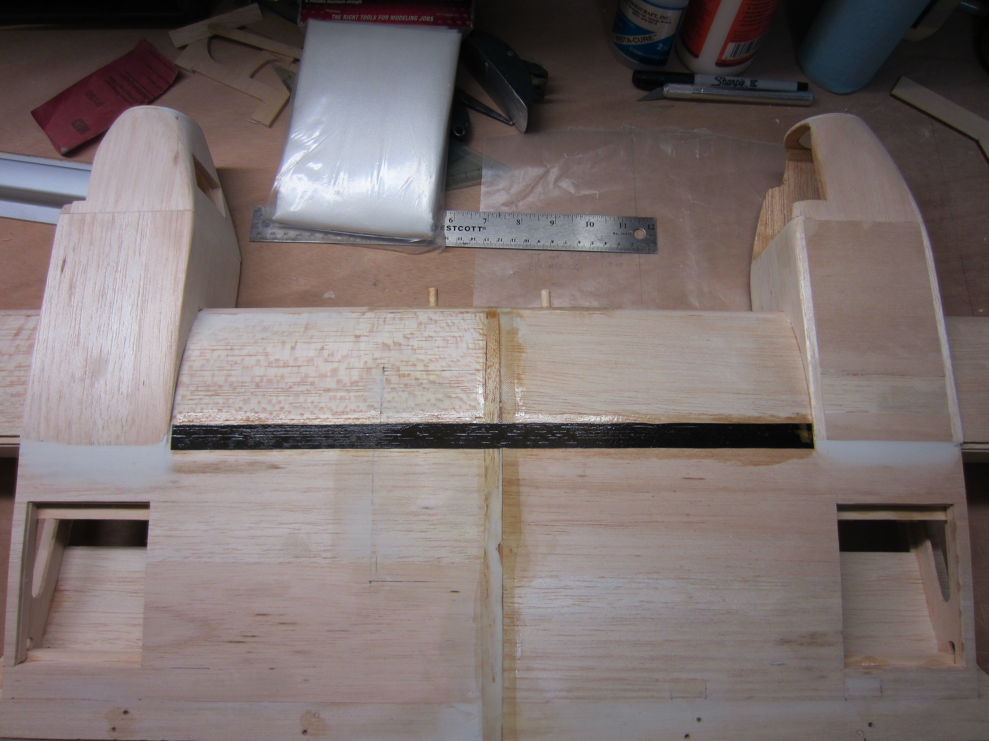
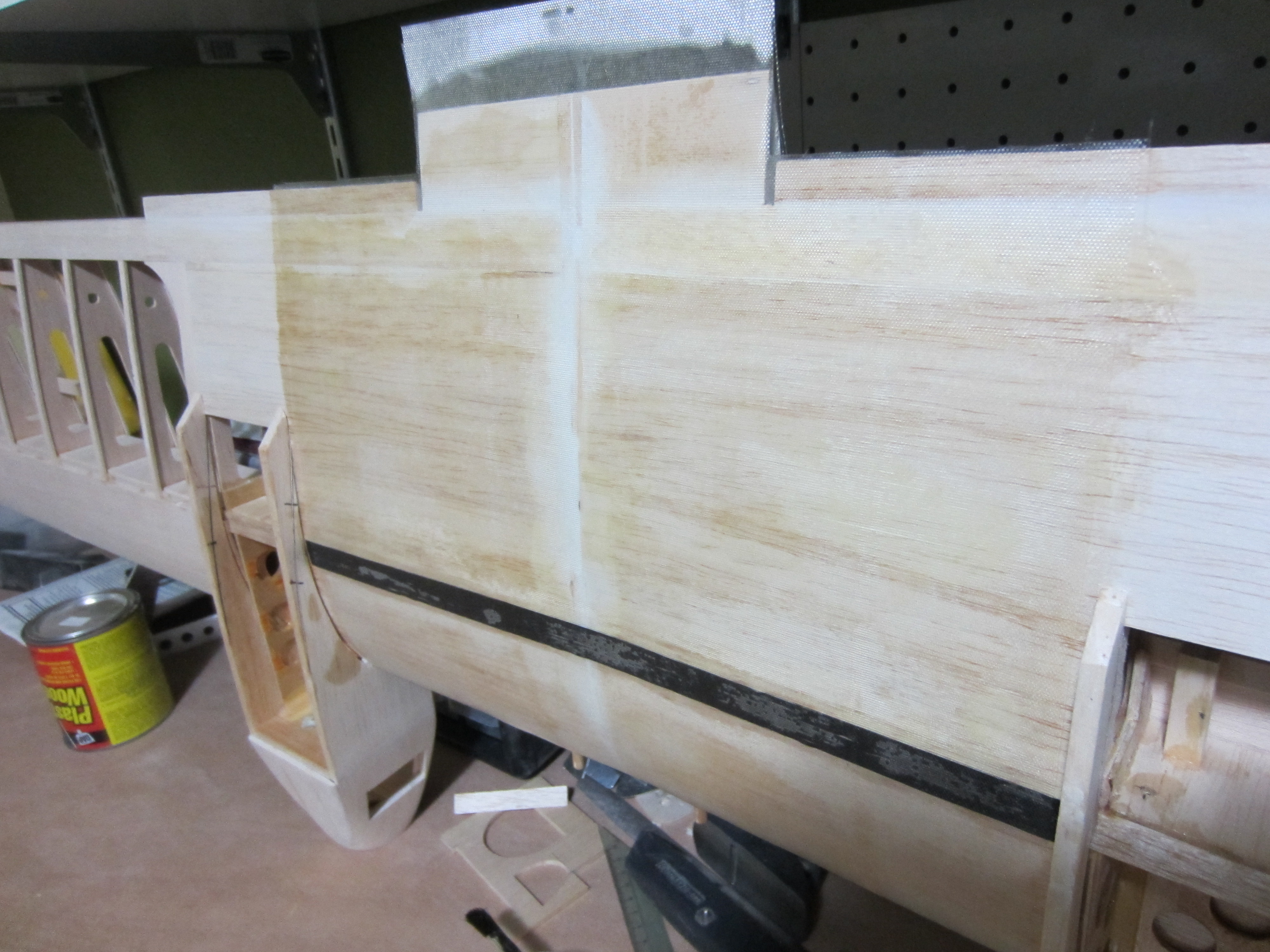
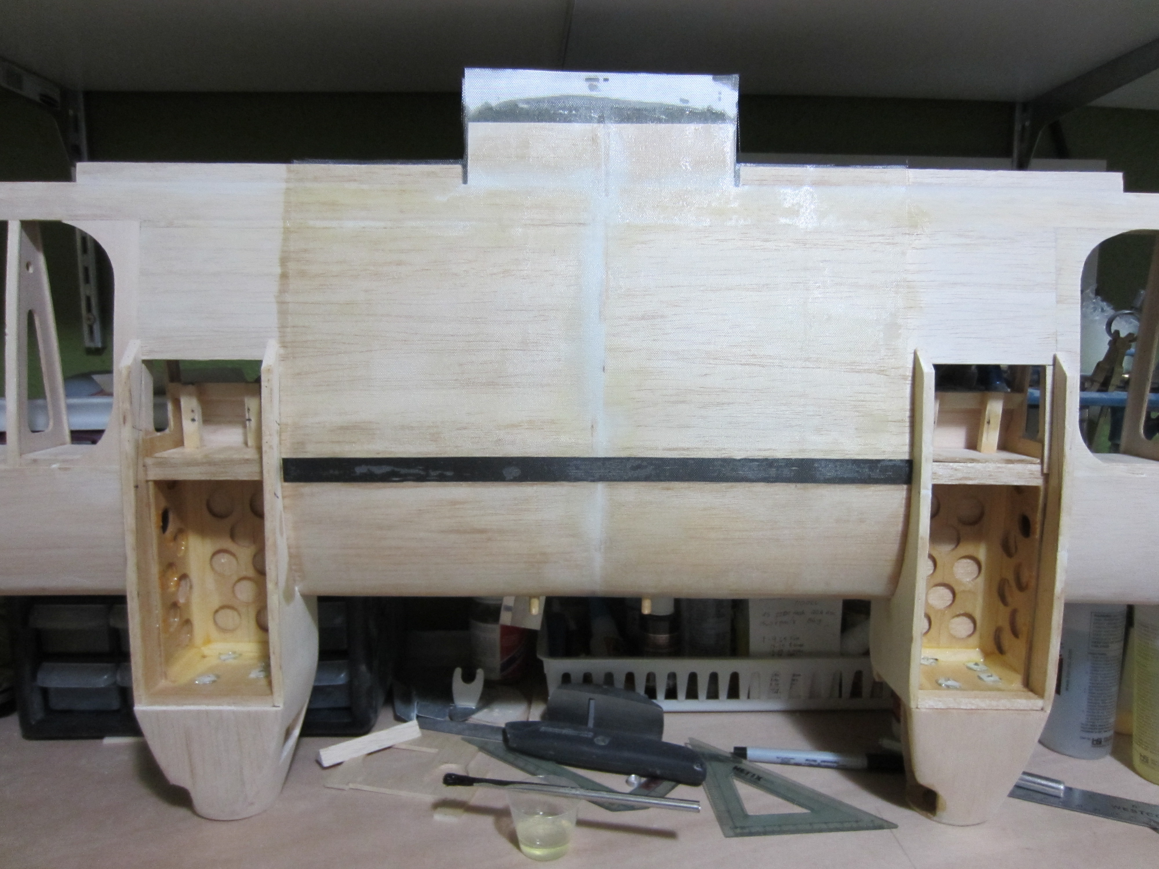
Wing joining time! I used the balsa wedge supplied in the kit, epoxied it in, then lined up the leading edges perfectly straight, then waited. Once that was dry, I reinforced top and bottom with a strip of carbon fiber. I wish I'd thought of it earlier in the build, but better late than never! After that was set, I covered the entire center section with 5 oz. fiberglass, using finishing resin. This is the first time I've done fiberglass, other than a few strips on other planes, and I'm happy with the way it turned out.
02-17-2014 | 08:11 PM
#22
Thread Starter
My Feedback: (11)
I thought of something the other day. Basically, the only pieces I used from the kit are the ribs, and the wing joining wedge, so I cut another set of ribs, and will build a mostly stock Super
Sportster. I have a few Super Tigre G-60s that need a home, so I'll choose a good one for this.
Sportster. I have a few Super Tigre G-60s that need a home, so I'll choose a good one for this.
02-18-2014 | 02:47 PM
#24
Thread Starter
My Feedback: (11)
Thanks Bill!
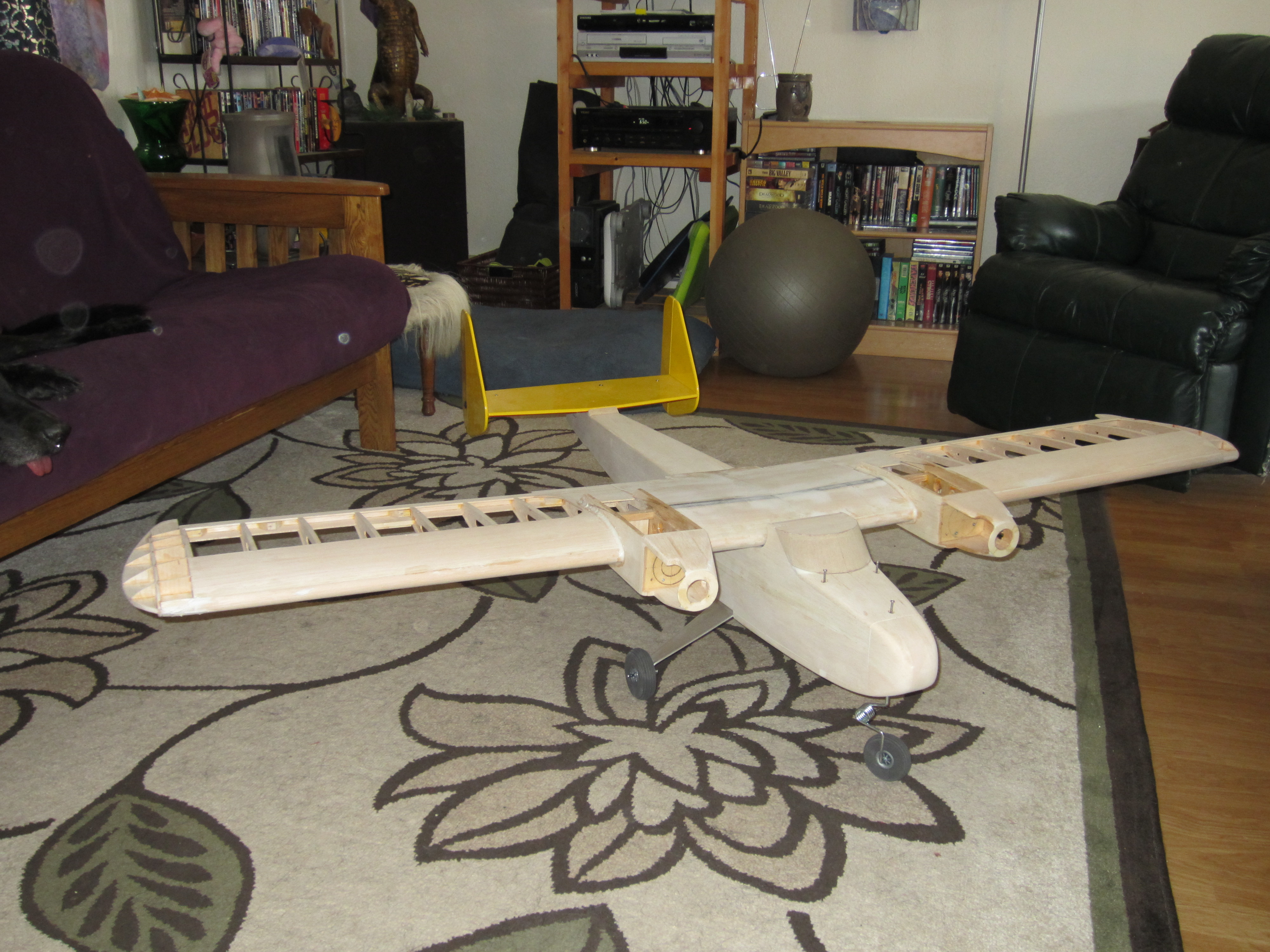
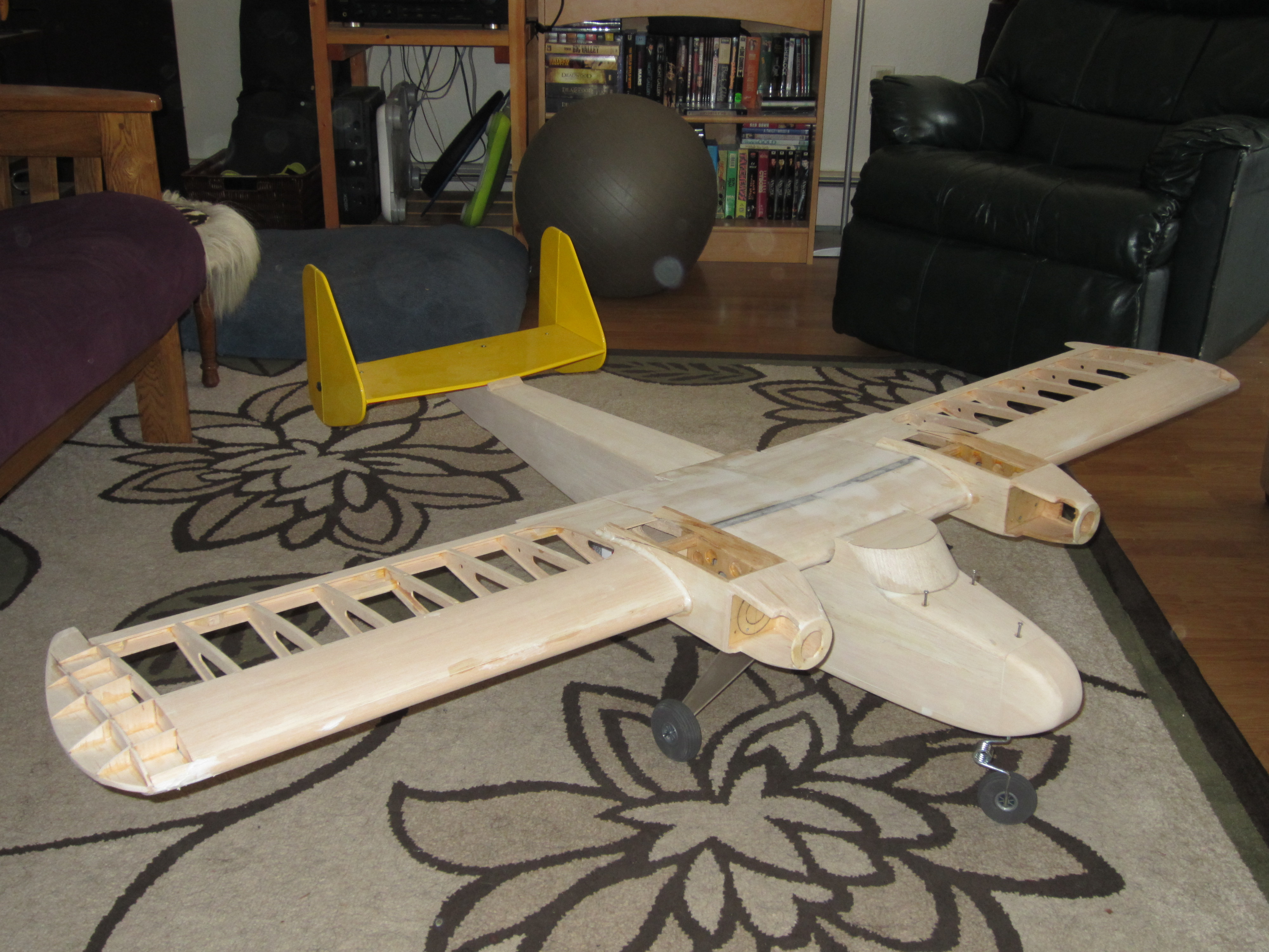
Here's a few pictures of the mock-up as it stand now.
I weighed all the assemblies and all the parts to finish the plane, and it totaled 7 lbs. 7 1/2 ounces. That's better than I had hoped!
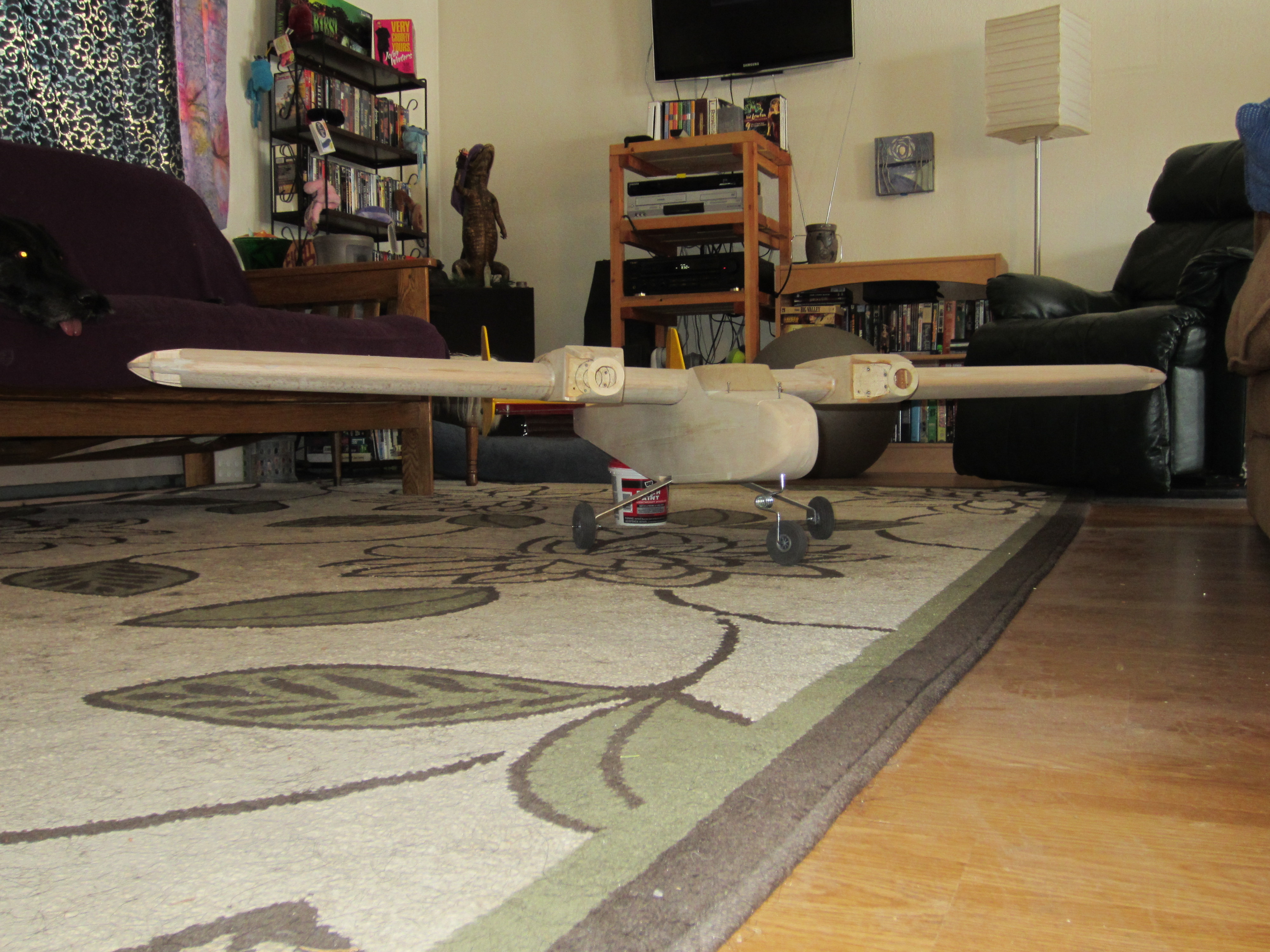
Here's a few pictures of the mock-up as it stand now.
I weighed all the assemblies and all the parts to finish the plane, and it totaled 7 lbs. 7 1/2 ounces. That's better than I had hoped!
Last edited by RDJeff; 02-18-2014 at 05:15 PM.

