


Glens Models 78" Cap232 ARF
 02-18-2015 | 07:14 AM
#26
Thread Starter

Joined: May 2003
Posts: 286
Likes: 0
Received 0 Likes
on
0 Posts
From: GIBRALTAR (Europe) GX11 1AA
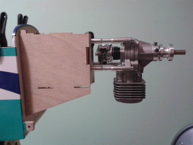
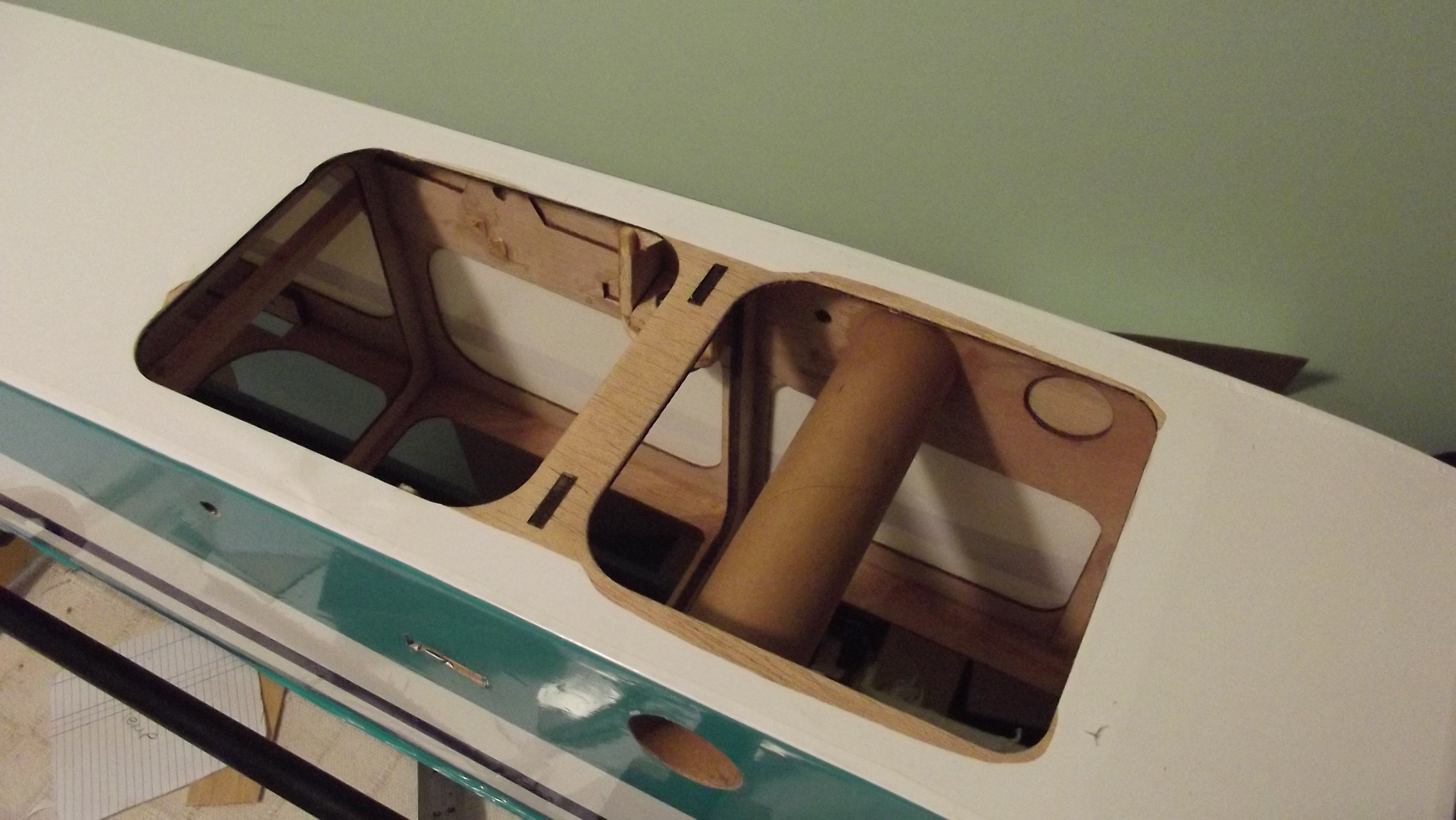
As i said before i have opted to mount the DLE30,
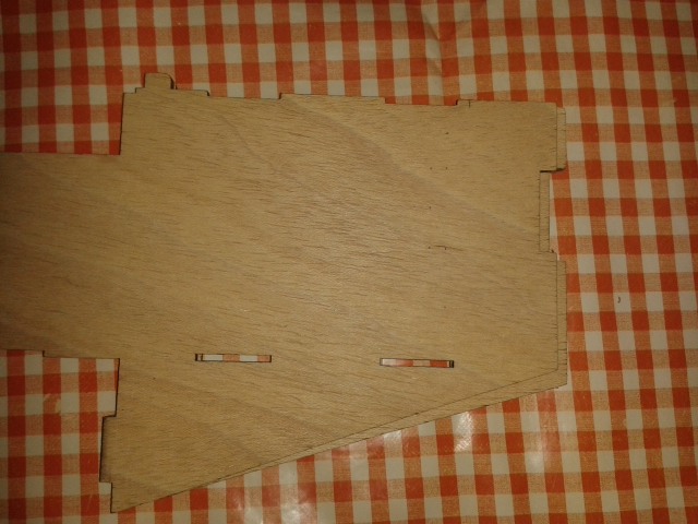
The DLE mounts are 60mm long so i hand to cut back the firewall side frames back 35mm.
I have pre mounted the 30 to the firewall to take the exact measurements like we all say measure twice cut once.
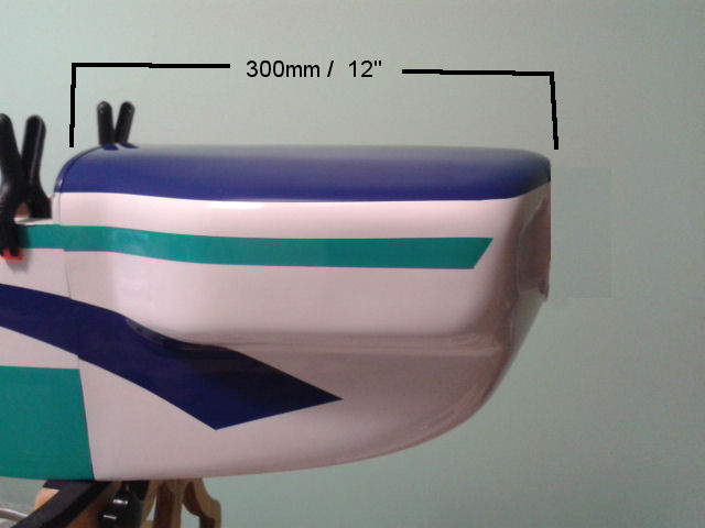
I have measured the distance from the trailing edge of the cowl to the leading edge i have a total measurement
of 300mm 12" inches then i measured back from the leading edge of the cowl to the firewall and would need a
total distance of 160mm this will give me a nice 5mm gap for my spinner.
The DLE mounts are 60mm long so i hand to cut back the firewall side frames back 35mm.
I have pre mounted the 30 to the firewall to take the exact measurements like we all say measure twice cut once.
I have measured the distance from the trailing edge of the cowl to the leading edge i have a total measurement
of 300mm 12" inches then i measured back from the leading edge of the cowl to the firewall and would need a
total distance of 160mm this will give me a nice 5mm gap for my spinner.
 02-18-2015 | 07:30 AM
#27
Thread Starter
Joined: May 2003
Posts: 286
Likes: 0
Received 0 Likes
on
0 Posts
From: GIBRALTAR (Europe) GX11 1AA
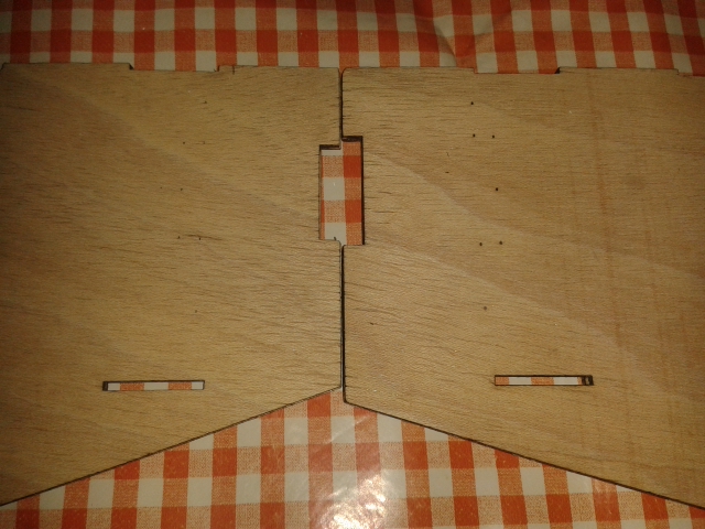
Placing bought sides together i have noticed that they are not the same what is going on here?
I know there has to be a difference of dimensions to compensate for the thrust angles i know she needs
3* right and 1* down but this is looks to me totally out of place.
Well i have done all my measurements to both sides that support the firewall and i have to cut back as
mentioned before 35mm and i also have to make the groves or cutouts to cut back in order to fit the firewall.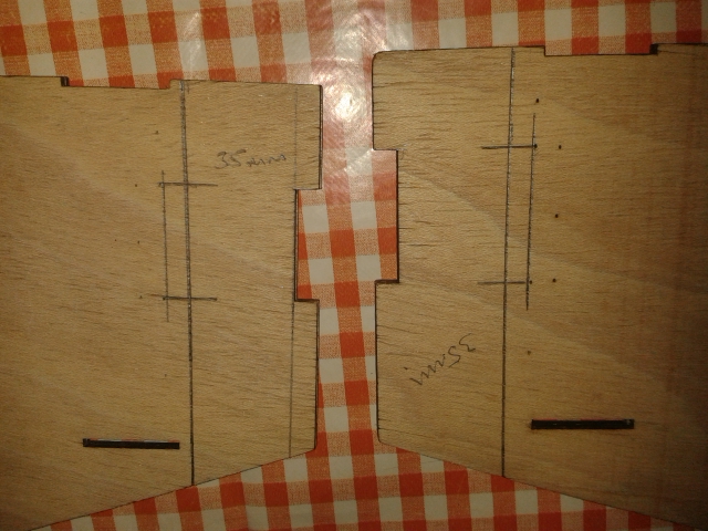
02-18-2015 | 07:40 AM
#28
Thread Starter
Joined: May 2003
Posts: 286
Likes: 0
Received 0 Likes
on
0 Posts
From: GIBRALTAR (Europe) GX11 1AA
After cutting out the side frames i have done a dry fit to the model just check if all is how it's suppose to be
a couple of clamps will do the trick.
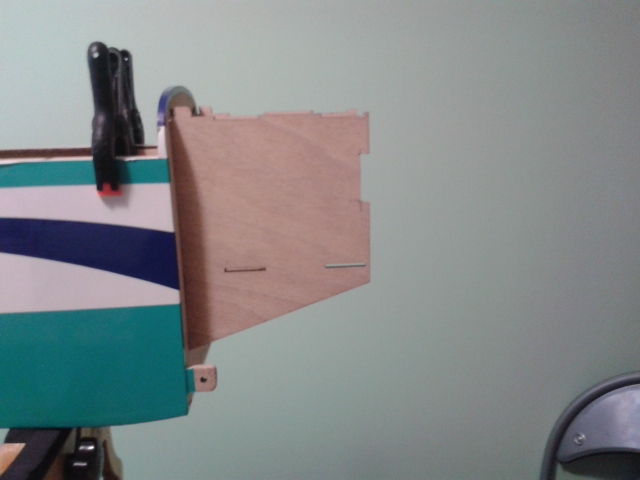
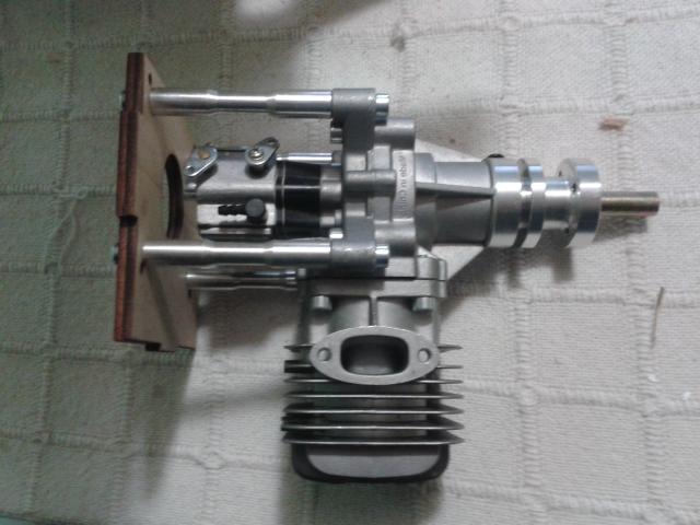
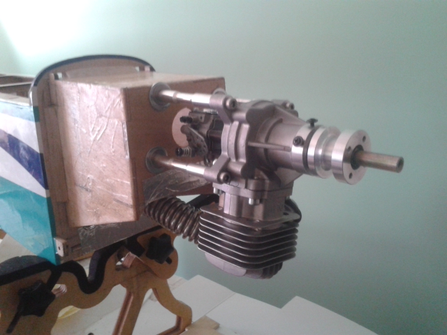
Hey she is looking good,i will try out the the firewall with the DLE30 pre installed.
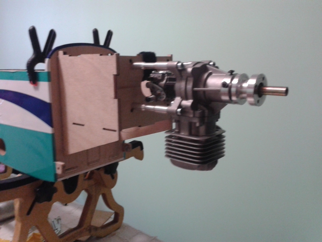
And here you have it DLE30 at the front of the Cap232.
let's see how we do with the fitting of the cowl hope all my measurements are correct.
a couple of clamps will do the trick.
Hey she is looking good,i will try out the the firewall with the DLE30 pre installed.
And here you have it DLE30 at the front of the Cap232.
let's see how we do with the fitting of the cowl hope all my measurements are correct.
02-18-2015 | 07:51 AM
#29
Thread Starter
Joined: May 2003
Posts: 286
Likes: 0
Received 0 Likes
on
0 Posts
From: GIBRALTAR (Europe) GX11 1AA
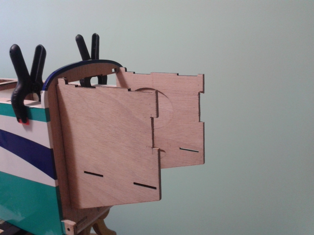
A little simple way to hold the engine and firewall to the side frames to do a dry run some cable ties
and a Velcro strap dose the trick.
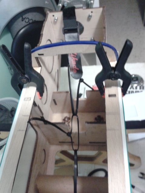
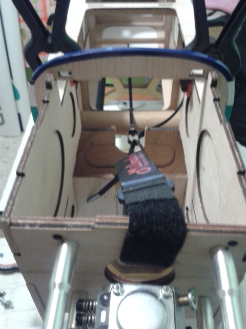
And now it's just a mutter of fitting the cowl.and i hope i have a 5mm clearance for my spinner.
and a Velcro strap dose the trick.
And now it's just a mutter of fitting the cowl.and i hope i have a 5mm clearance for my spinner.
02-18-2015 | 08:02 AM
#30
Thread Starter
Joined: May 2003
Posts: 286
Likes: 0
Received 0 Likes
on
0 Posts
From: GIBRALTAR (Europe) GX11 1AA
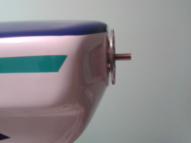
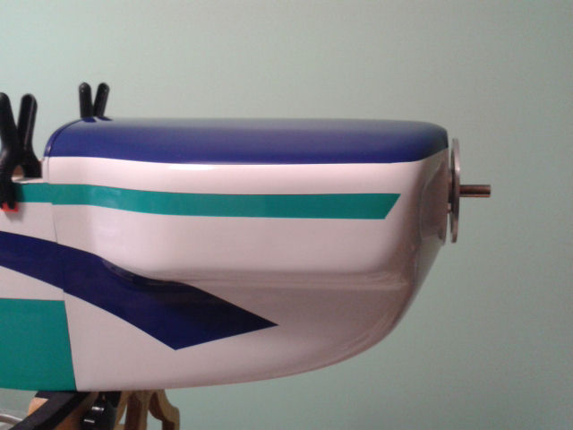
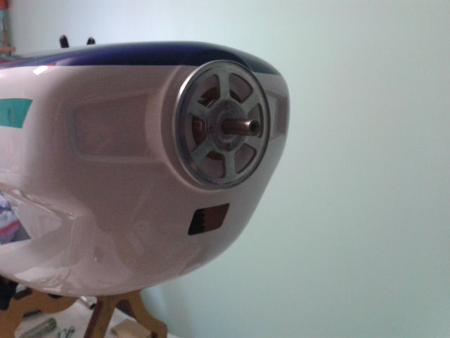
I have just fitted the cowl you tell me dose she look cool or what.
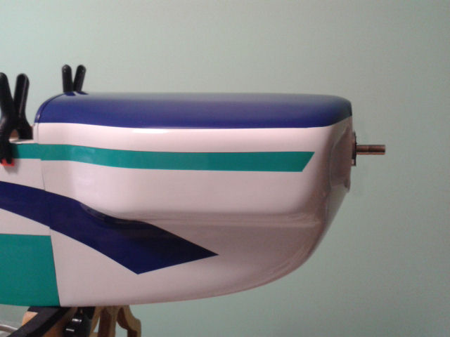
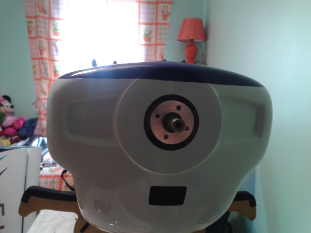
Placed the spinner back plate looks to me that's fine and if i need to come out just that bit
with a nice washer will do it's job.
Well i just need to epoxy all the wood to the fuselage do some needed re enforcements to that
flimsy side frames and we should be good to start installing the rest off the goodies.
Last edited by Francis L M; 02-18-2015 at 08:24 AM.
02-20-2015 | 06:01 AM
#33
Thread Starter
Joined: May 2003
Posts: 286
Likes: 0
Received 0 Likes
on
0 Posts
From: GIBRALTAR (Europe) GX11 1AA
I have had to re right the book,
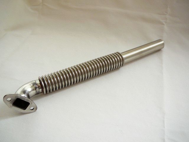
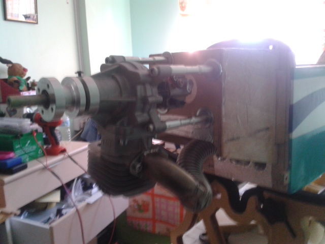
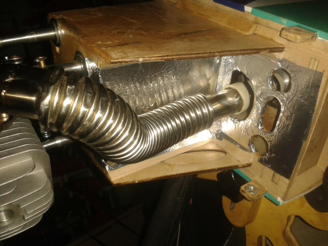
After installing the Exhaust manifold with flexible tube it was just not fit the cowl without having to cut around the the flexible tube.

So here we back to the drawing board.
I have made a template of the firewall with some cardboard i had lying around.
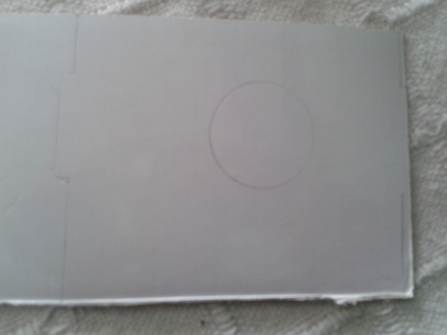
I placed the cardboard copy on top off my existing fire wall and rotated it about 6* to the right,
this will hopefully give me just enough clearance so that the exhaust manifold with the flexible tube
will not hit the side of the cowl.
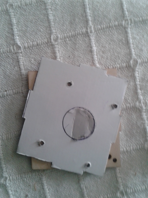
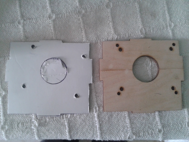
The center hole gave me the exact position so i did not lose the engines center line and the thrust angles.
how i just need to re drill the fire wall and fit the engine and go for a dry fit.
After installing the Exhaust manifold with flexible tube it was just not fit the cowl without having to cut around the the flexible tube.
So here we back to the drawing board.
I have made a template of the firewall with some cardboard i had lying around.
I placed the cardboard copy on top off my existing fire wall and rotated it about 6* to the right,
this will hopefully give me just enough clearance so that the exhaust manifold with the flexible tube
will not hit the side of the cowl.
The center hole gave me the exact position so i did not lose the engines center line and the thrust angles.
how i just need to re drill the fire wall and fit the engine and go for a dry fit.
02-20-2015 | 06:12 AM
#34
Thread Starter
Joined: May 2003
Posts: 286
Likes: 0
Received 0 Likes
on
0 Posts
From: GIBRALTAR (Europe) GX11 1AA
I have installed the engine with the exhaust manifold with flexible tube to the fire wall,
with some clamps and elastic bands will do the trick for a dry fit.
Can't say she doesn't look great.
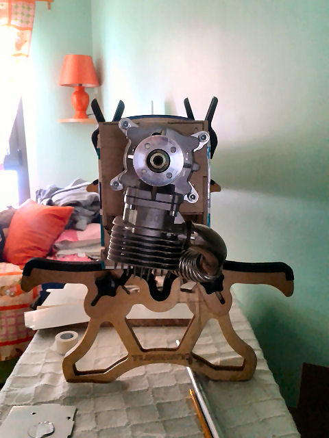
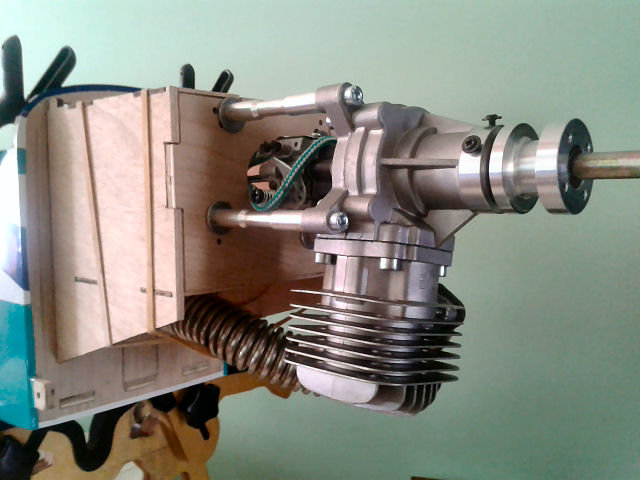
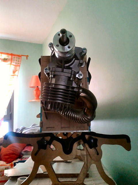
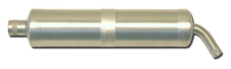
I just had to have a tune pipe installed this will make my model engine perform better and
of cause at the same time the noise reduction will impressive."Noise pollution"
with some clamps and elastic bands will do the trick for a dry fit.
Can't say she doesn't look great.
I just had to have a tune pipe installed this will make my model engine perform better and
of cause at the same time the noise reduction will impressive."Noise pollution"
02-20-2015 | 06:15 AM
#35
Thread Starter
Joined: May 2003
Posts: 286
Likes: 0
Received 0 Likes
on
0 Posts
From: GIBRALTAR (Europe) GX11 1AA
Sow here you have it the cowl installed and know with no issues with my exhaust manifold with flexible tube
how about this job done another thing out of the way.


how about this job done another thing out of the way.
02-27-2015 | 11:48 PM
#37
Thread Starter
Joined: May 2003
Posts: 286
Likes: 0
Received 0 Likes
on
0 Posts
From: GIBRALTAR (Europe) GX11 1AA
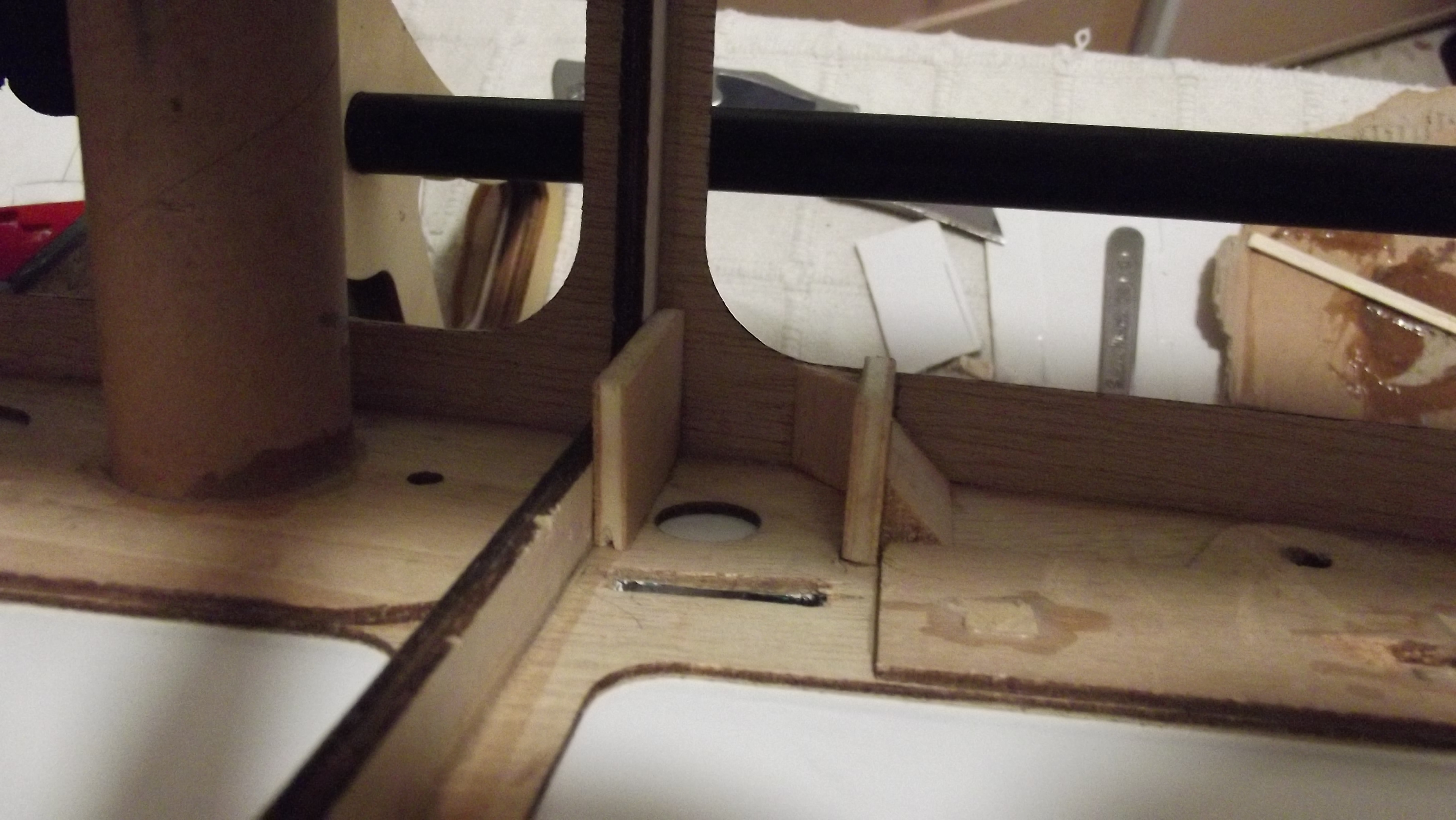
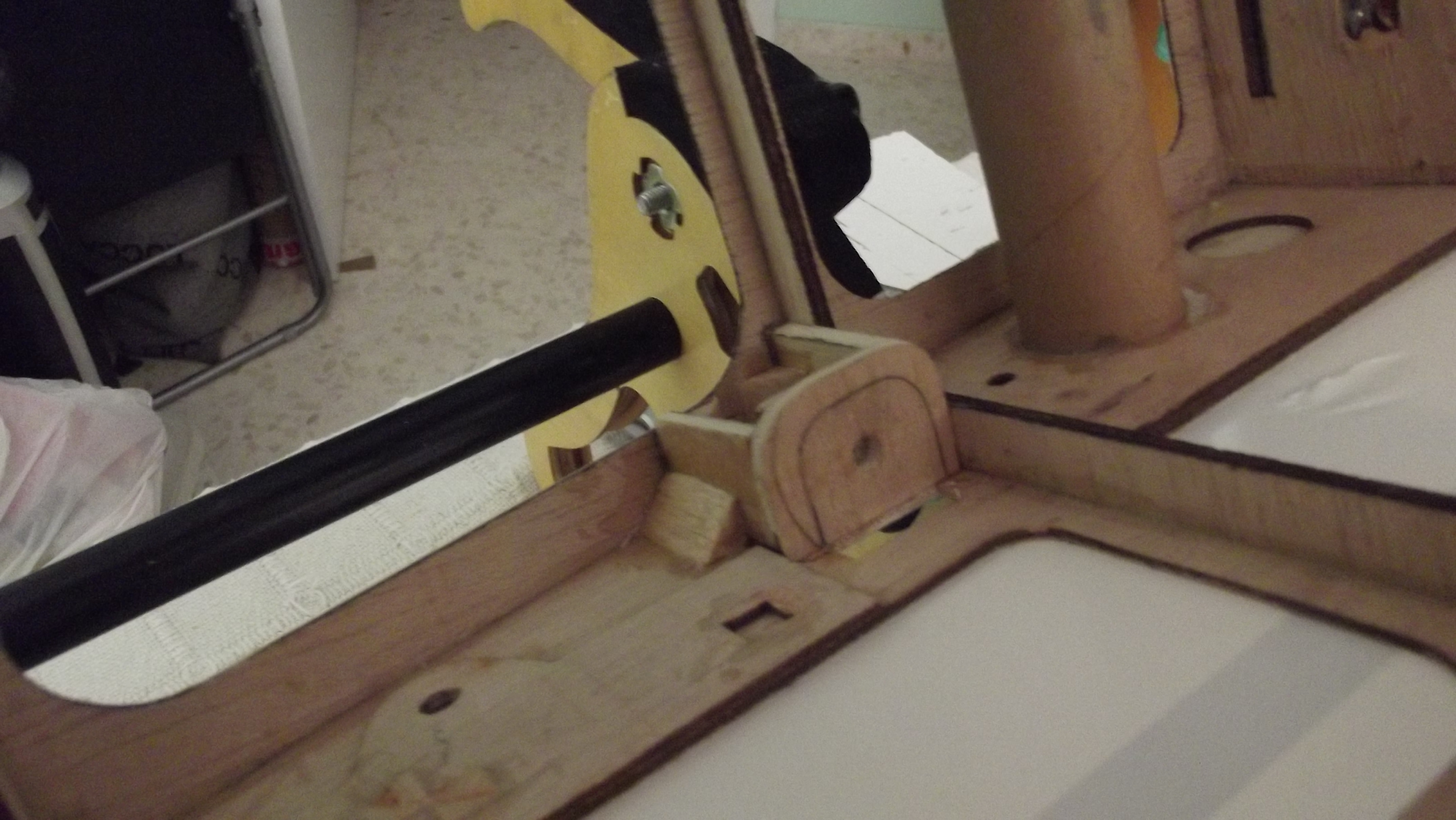
I have stared the assembly of the wing fixture to the fuselage by drawing out and making
some templates of cardboard.
I then cut two set's of them out from lite ply.
Placed them into position and glued them with epoxy added for extra strength some triangle cut offs of balsa.
some templates of cardboard.
I then cut two set's of them out from lite ply.
Placed them into position and glued them with epoxy added for extra strength some triangle cut offs of balsa.
02-28-2015 | 12:05 AM
#38
Thread Starter
Joined: May 2003
Posts: 286
Likes: 0
Received 0 Likes
on
0 Posts
From: GIBRALTAR (Europe) GX11 1AA
going to the wing i clamped to the wing the top ply where i will be
adding together with an added ply with the blind nut.
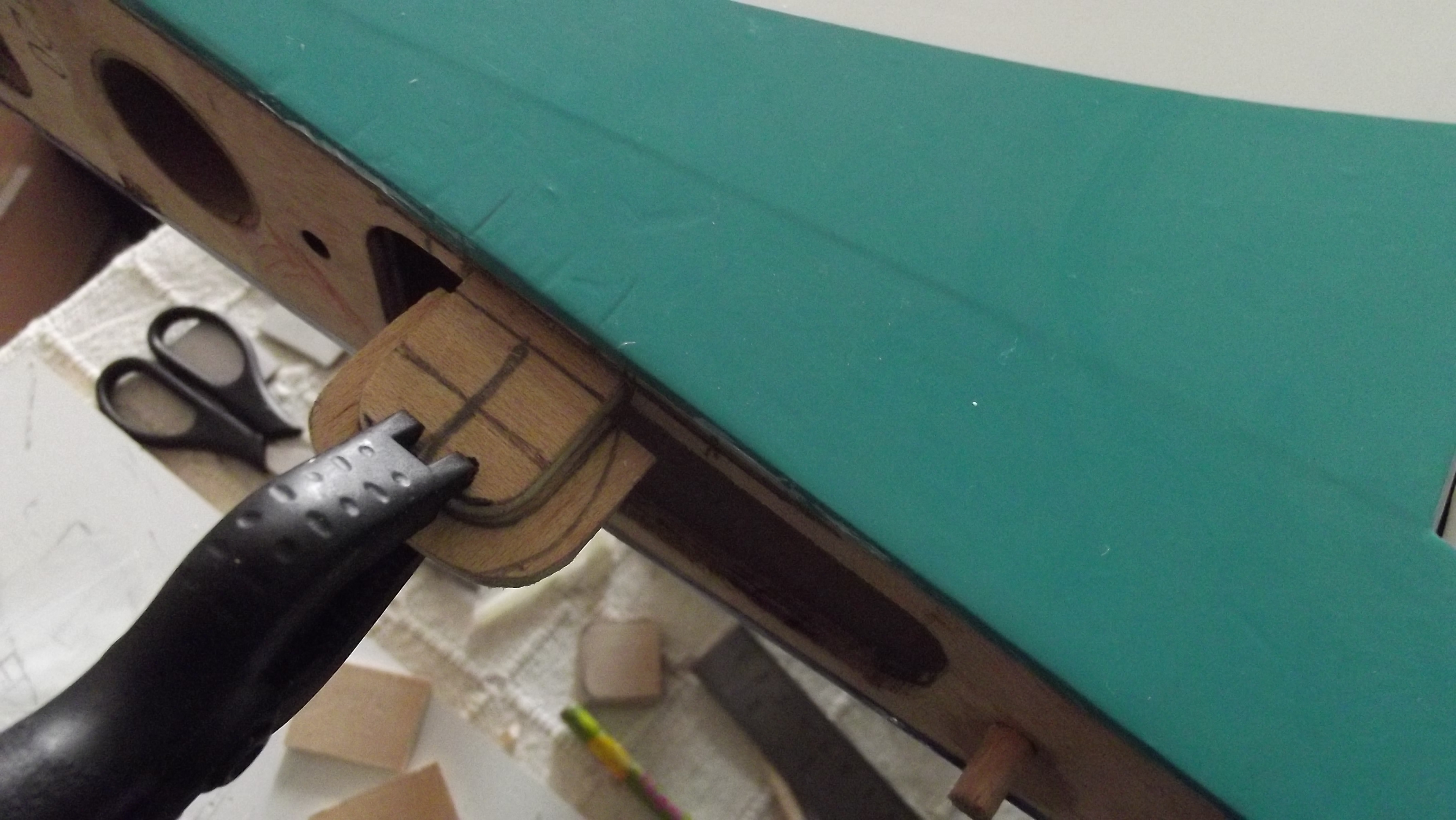 As you can see i measured the center so i can drill the hole for the nylon screw and blind nut.
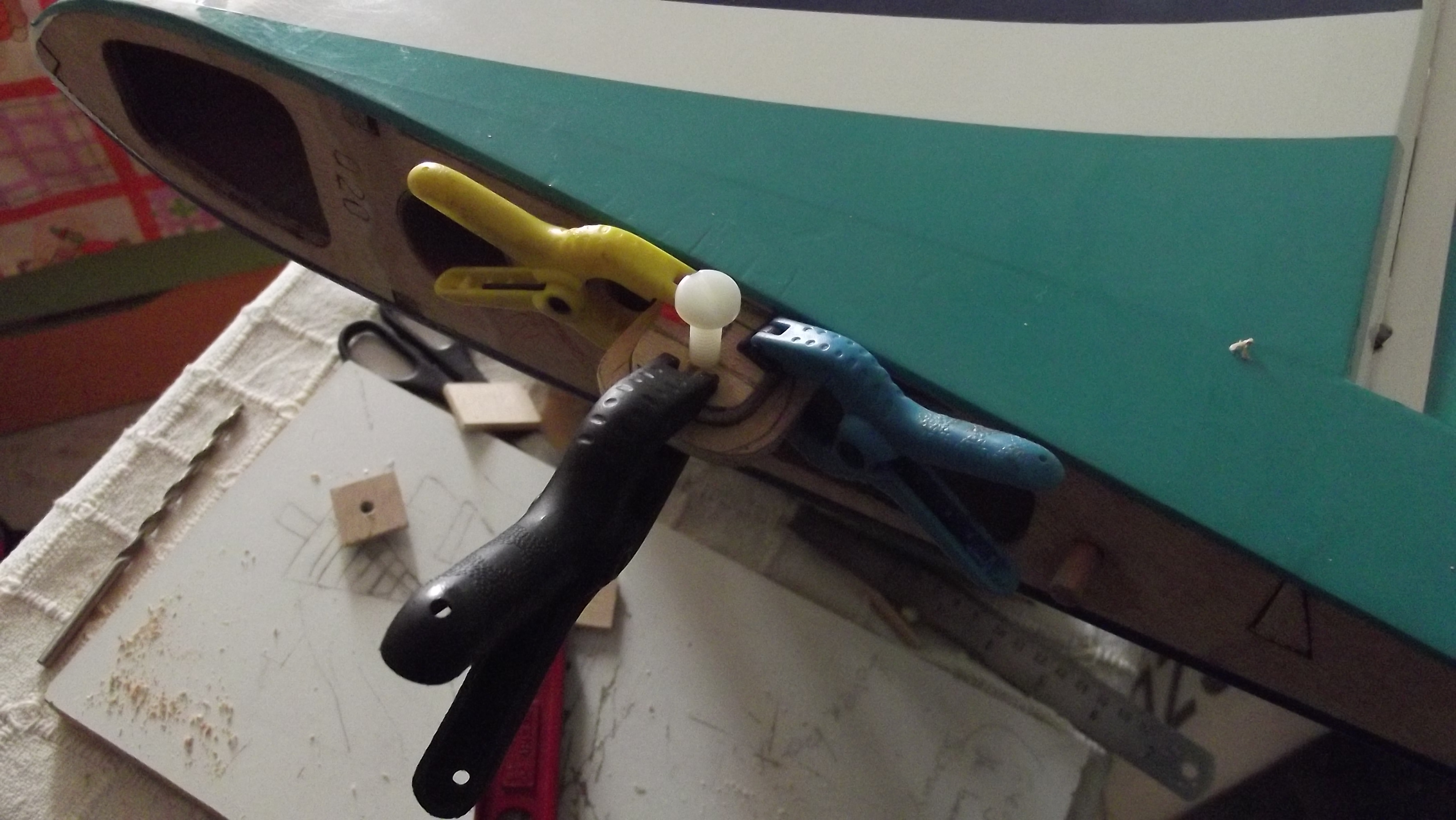

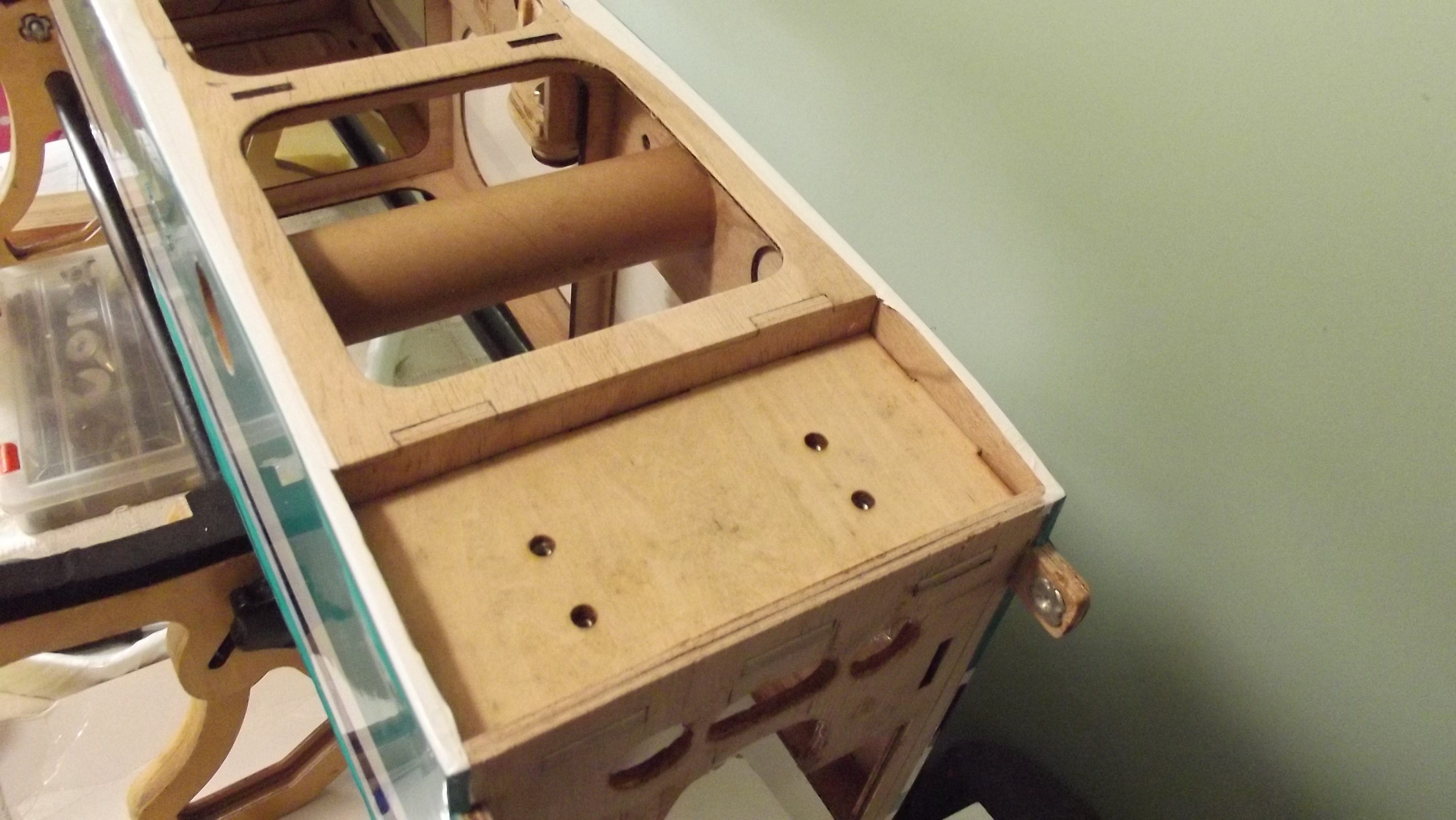
After drilling the hole and adding the extra piece of ply i place it on the fuselage to try out a dry fit just to check if all was inline.

I have glued with epoxy all the parts and now the moment of the truth i have installed the wing and i have to say
it was well worth the had work just what a simple way to fasten the wing.

adding together with an added ply with the blind nut.
After drilling the hole and adding the extra piece of ply i place it on the fuselage to try out a dry fit just to check if all was inline.
I have glued with epoxy all the parts and now the moment of the truth i have installed the wing and i have to say
it was well worth the had work just what a simple way to fasten the wing.
02-28-2015 | 12:07 AM
#39
Thread Starter
Joined: May 2003
Posts: 286
Likes: 0
Received 0 Likes
on
0 Posts
From: GIBRALTAR (Europe) GX11 1AA
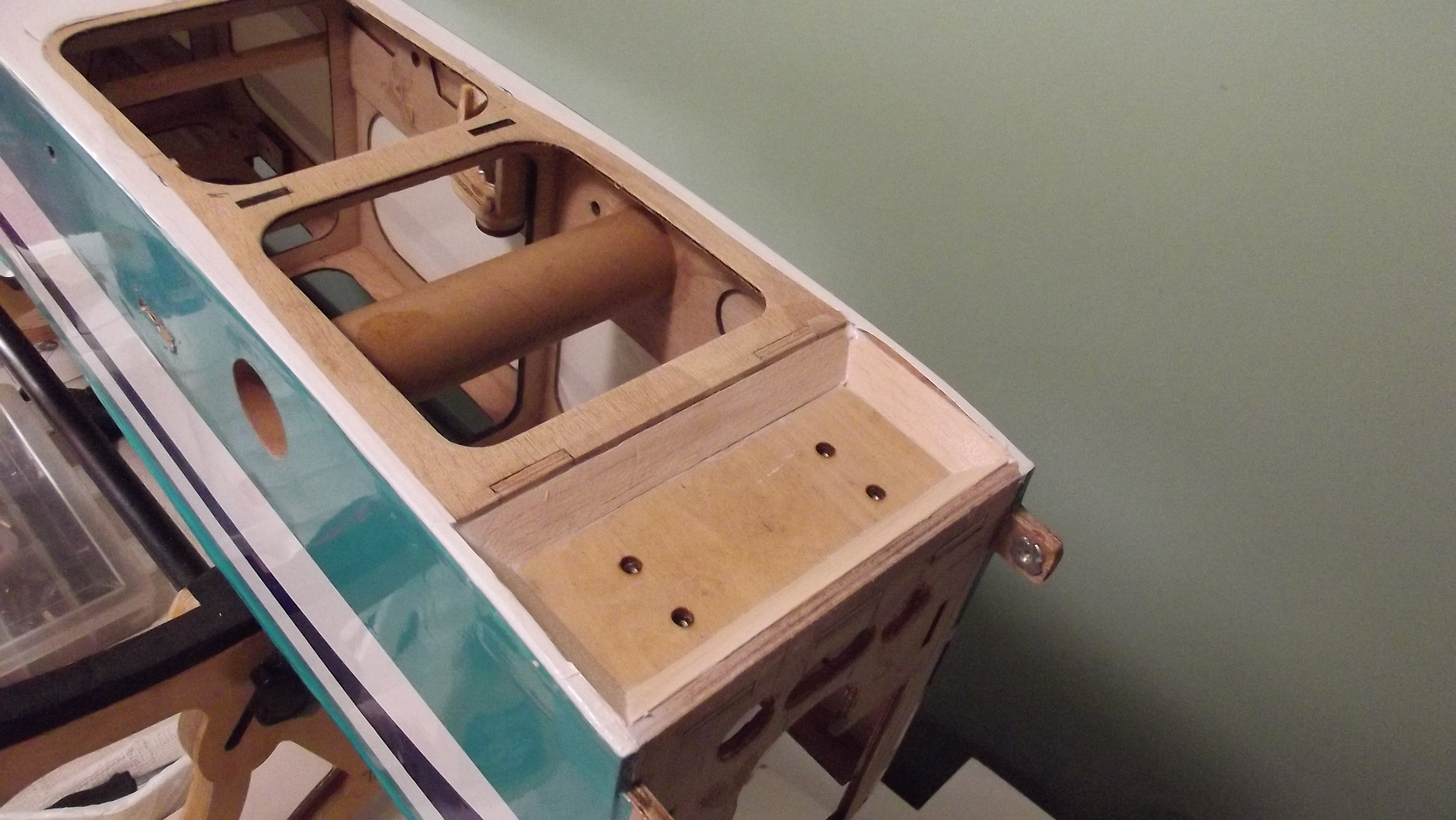
Sow here you go my wing is know sorted with an easy and a quick way to install and fasten the wing.
i am going to start finishing with the engine box so i can install the flexible manifold and tune pipe.
i am going to start finishing with the engine box so i can install the flexible manifold and tune pipe.
02-28-2015 | 12:22 AM
#40
Thread Starter
Joined: May 2003
Posts: 286
Likes: 0
Received 0 Likes
on
0 Posts
From: GIBRALTAR (Europe) GX11 1AA
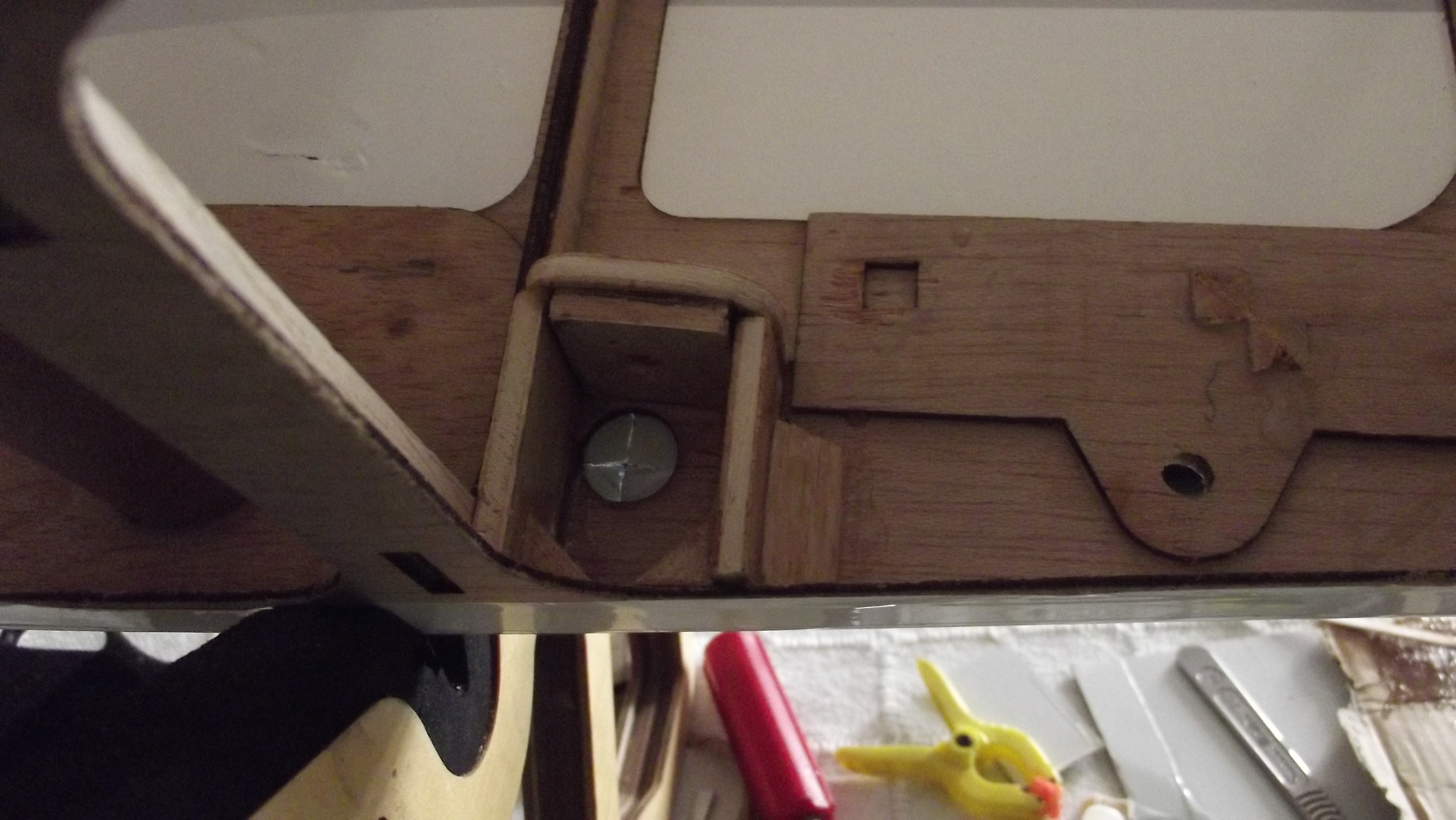
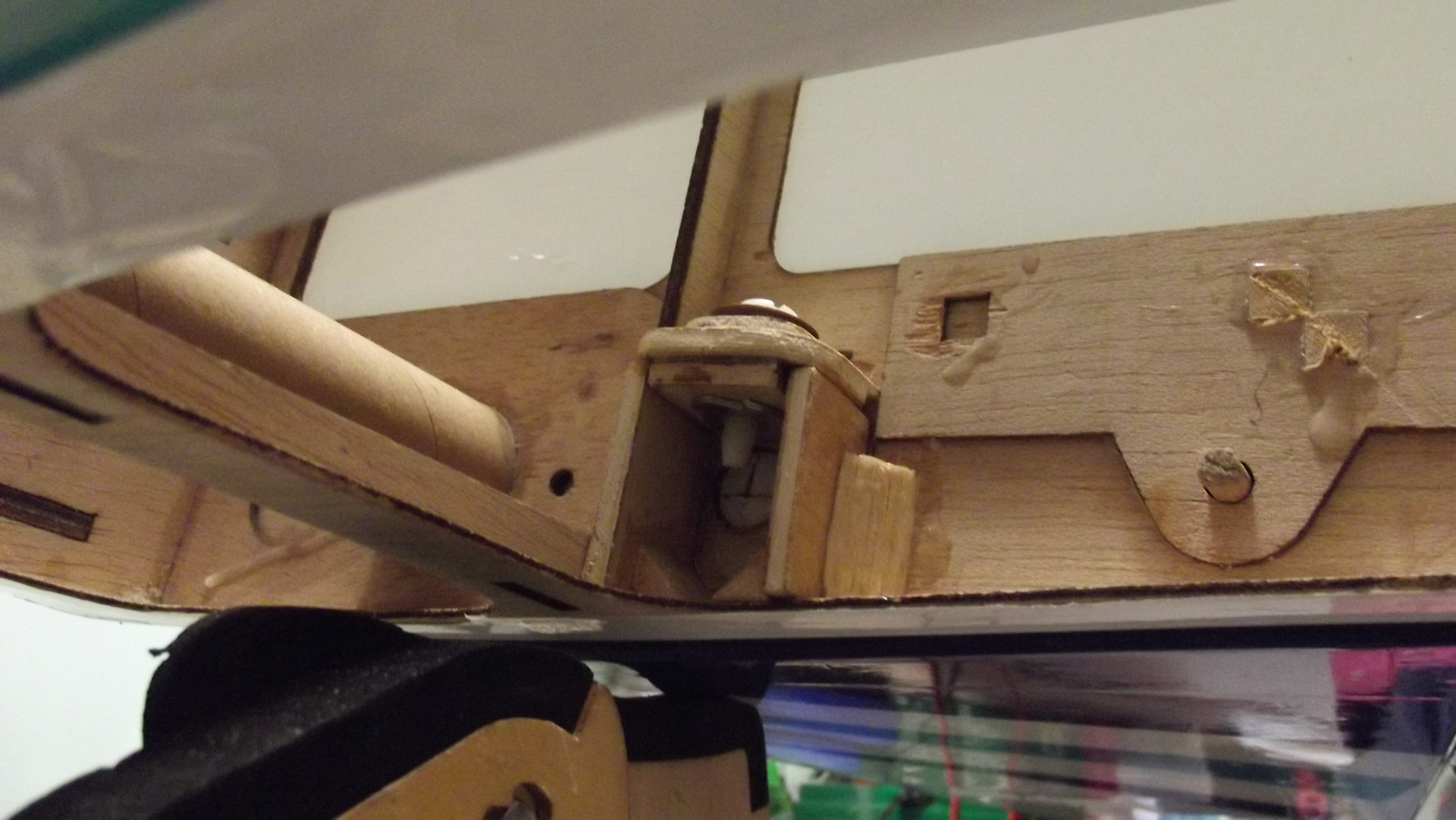
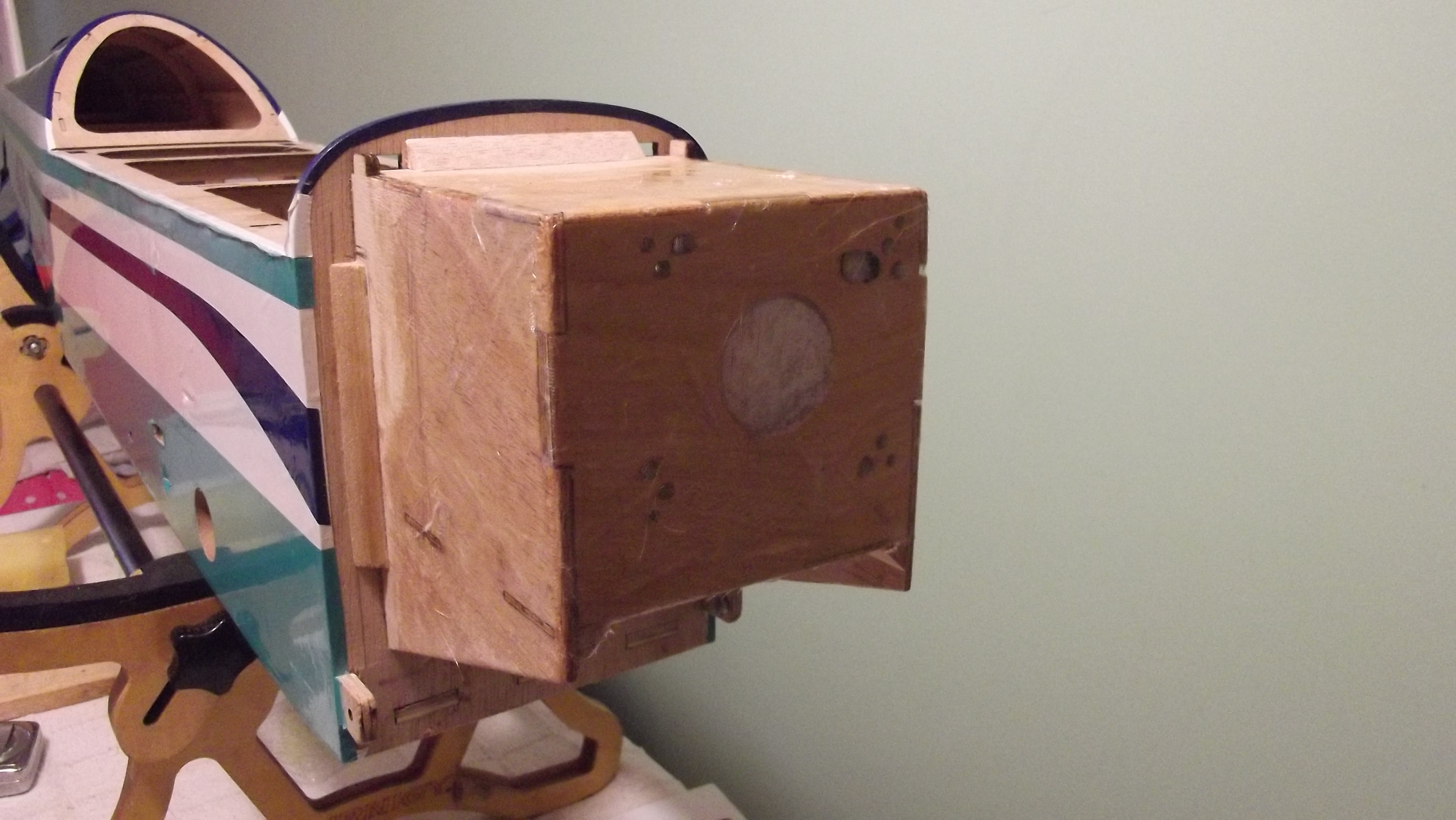
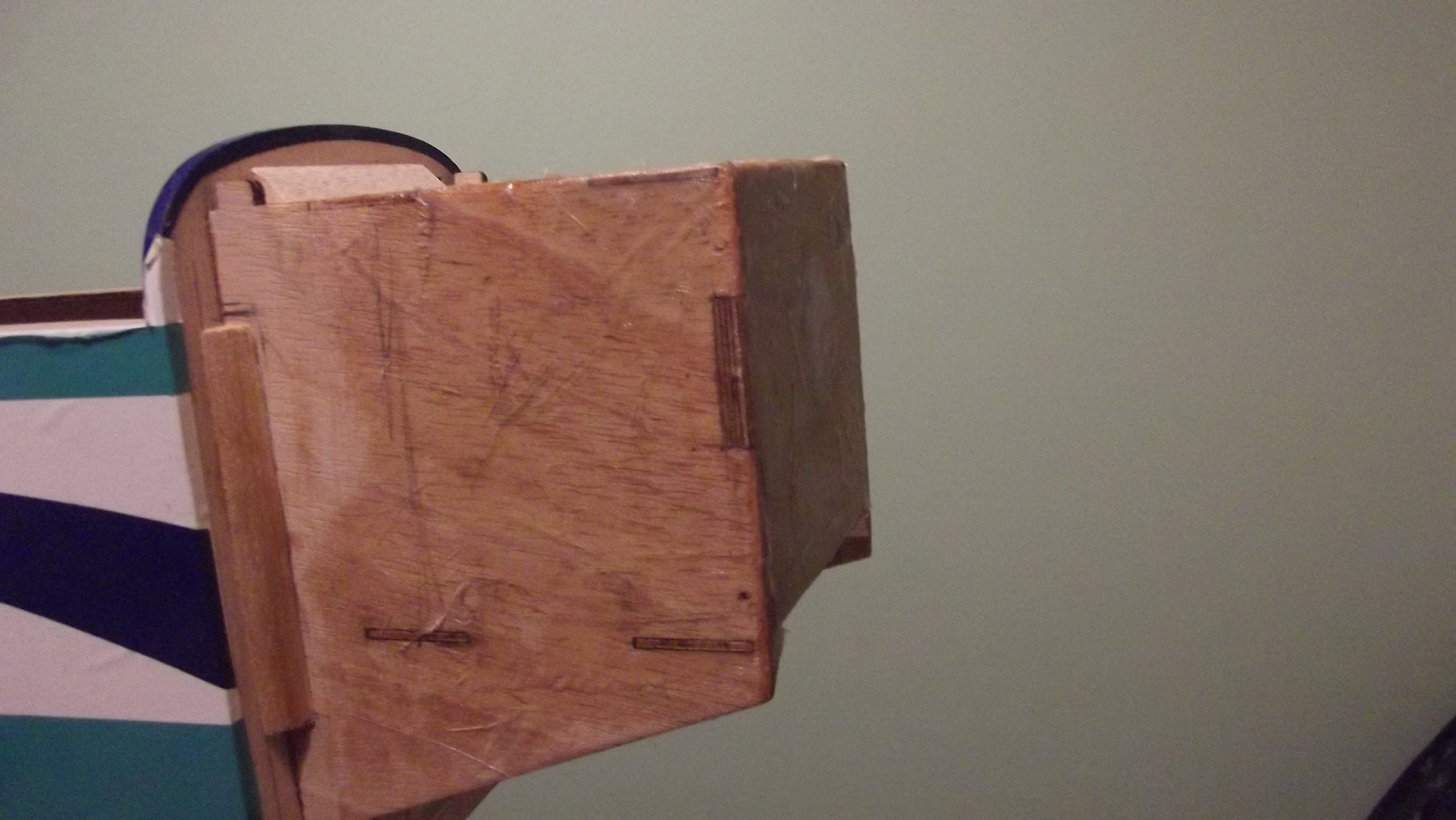
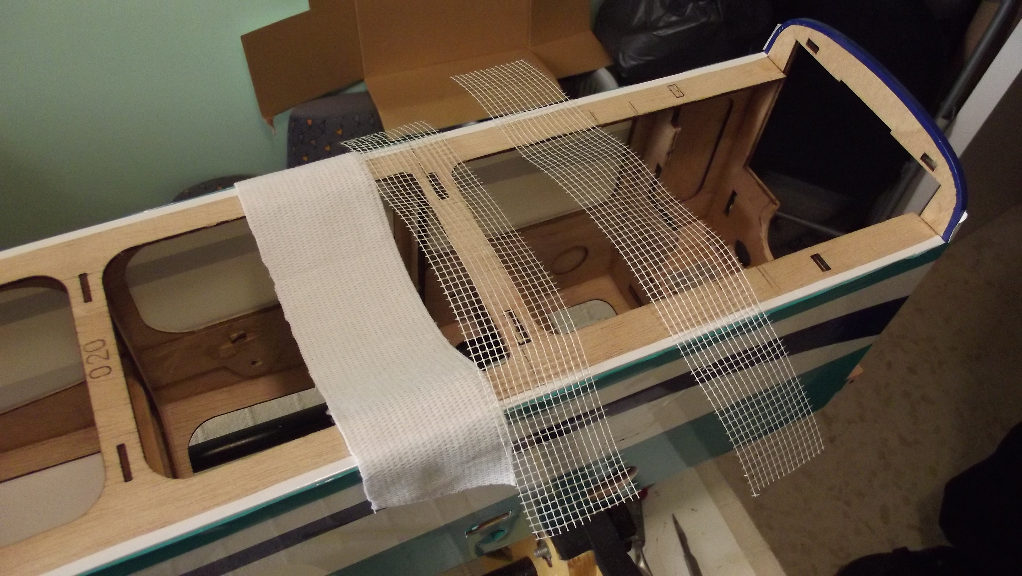
I have put together the engine box and glued it to the fuselage with epoxy.
i have also added to re enforce the box to the F2 some triangle balsa wood around and at the under neath of the box.
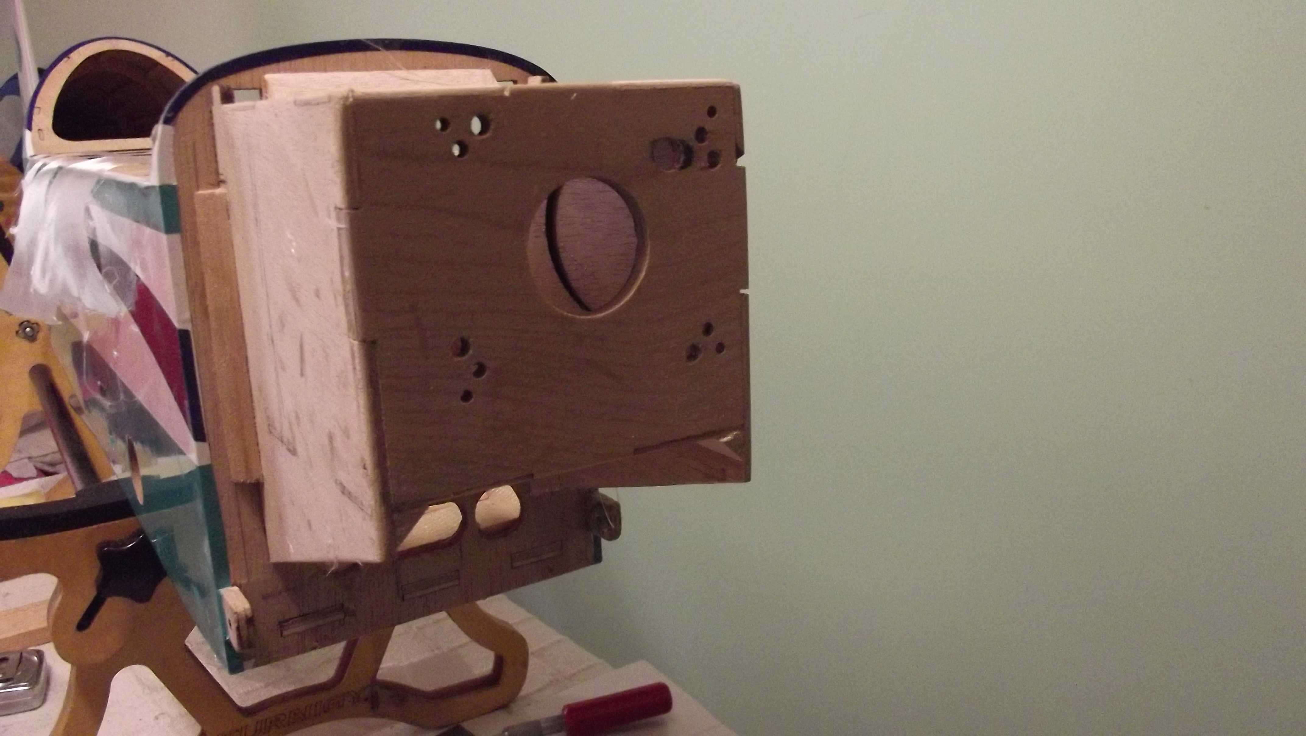
After i epoxied the fire wall to the engine box i have a dded as an extra security i drilled some 2mm holes
all round the fire wall and added had wood pins with wood glue.

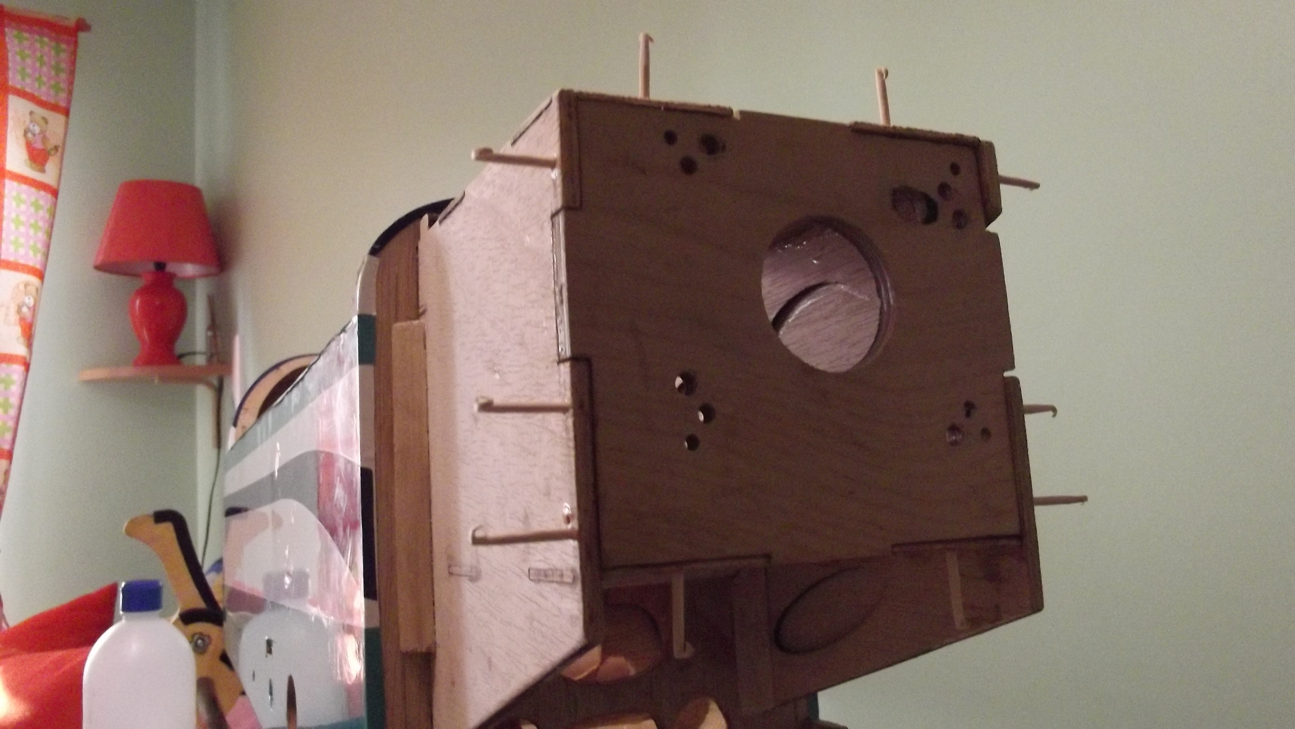
I cut flush all the dowels and sanded all the engine box smooth to add the fiber glass cloth to the fire wall this
will make it stronger and fuel proof at the same time.

A very thin fiber glass cloth from fiber tech with 1 hour epoxy dose the trick.
i have also added to re enforce the box to the F2 some triangle balsa wood around and at the under neath of the box.
After i epoxied the fire wall to the engine box i have a dded as an extra security i drilled some 2mm holes
all round the fire wall and added had wood pins with wood glue.
I cut flush all the dowels and sanded all the engine box smooth to add the fiber glass cloth to the fire wall this
will make it stronger and fuel proof at the same time.
A very thin fiber glass cloth from fiber tech with 1 hour epoxy dose the trick.
02-28-2015 | 12:28 AM
#41
Thread Starter
Joined: May 2003
Posts: 286
Likes: 0
Received 0 Likes
on
0 Posts
From: GIBRALTAR (Europe) GX11 1AA
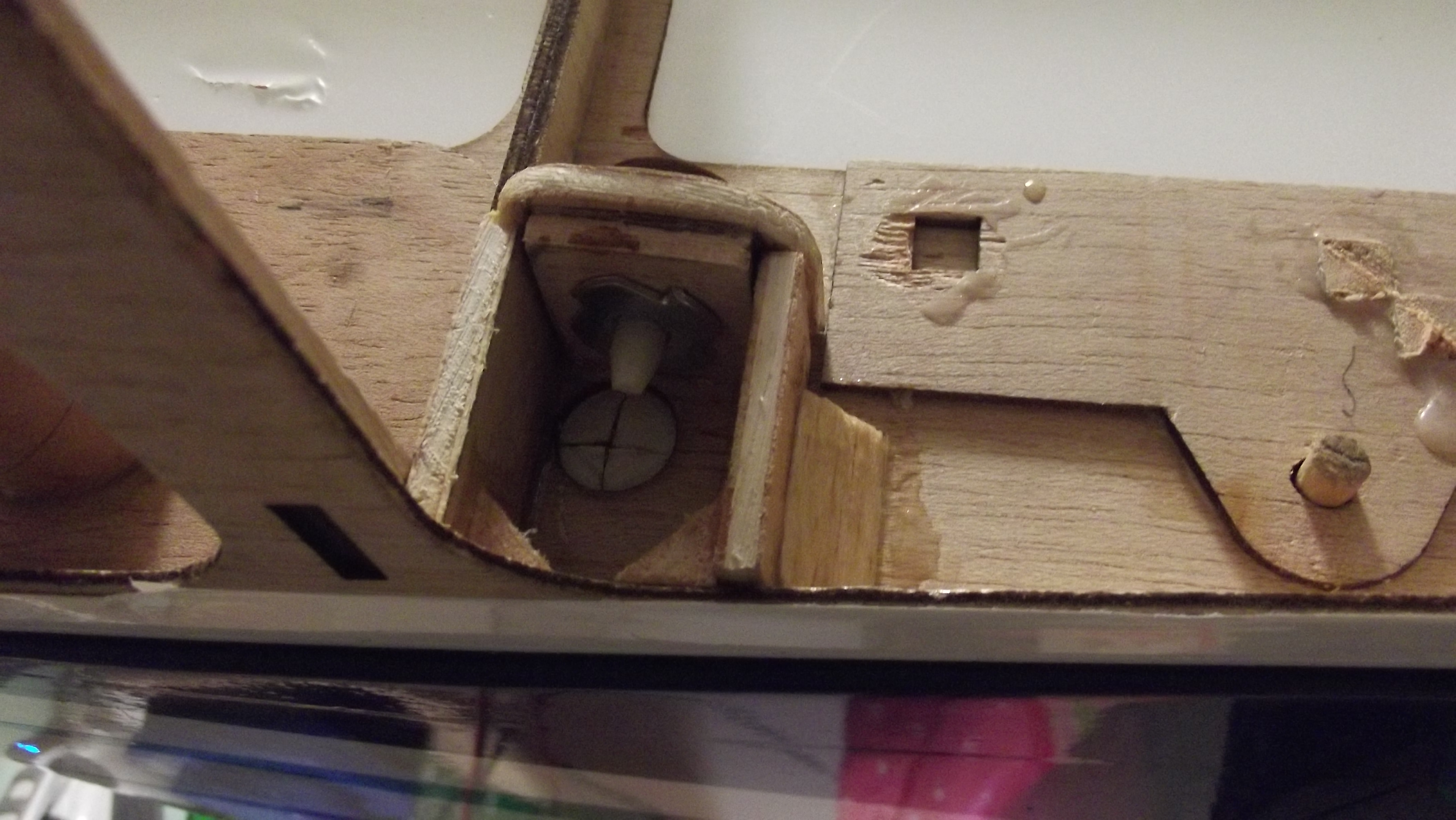
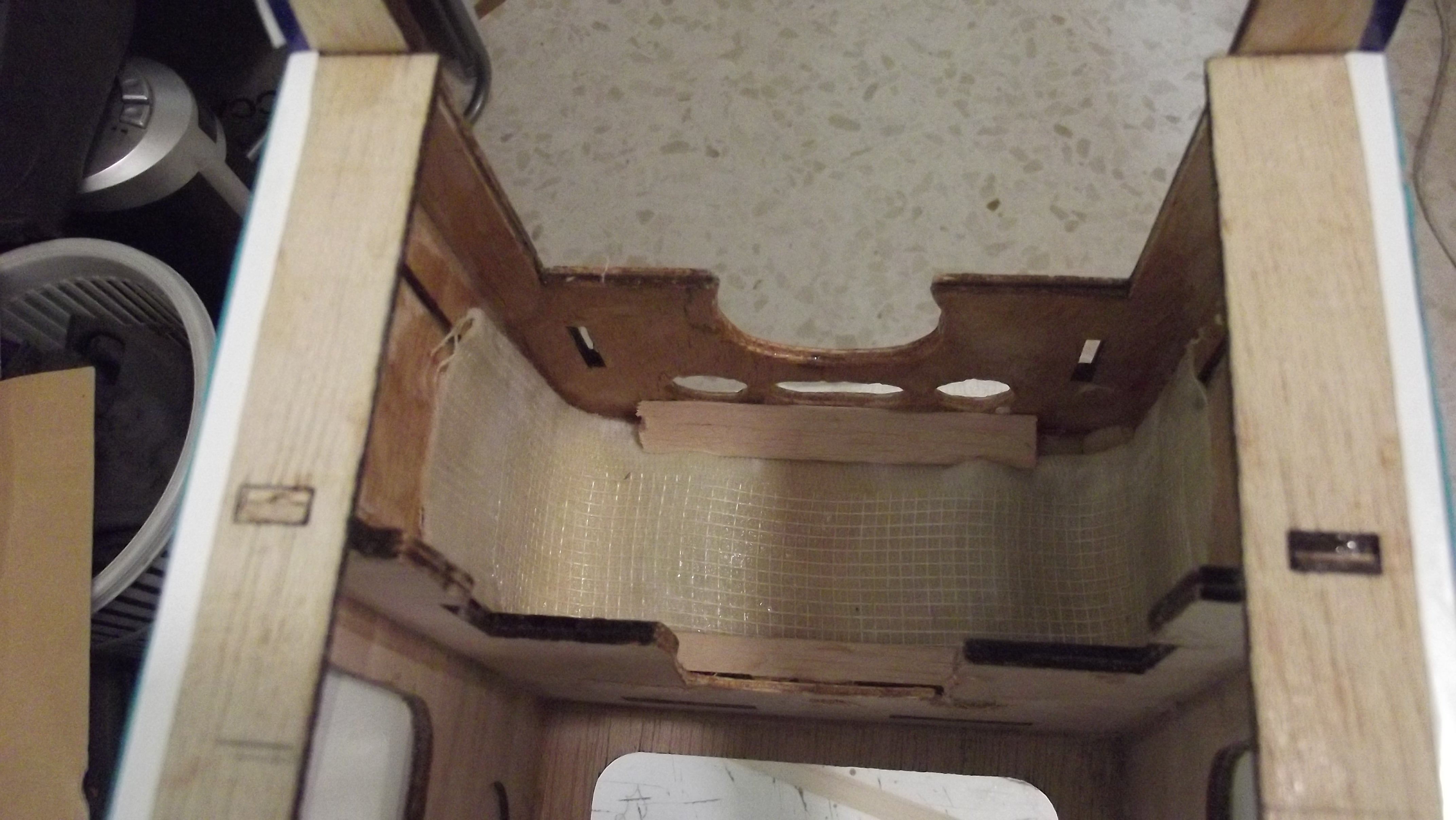
And this is how it looks after the fiber glass has cured she is know read to install the engine.
i now have a strong and light weight engine box and fuel proof at the same time.
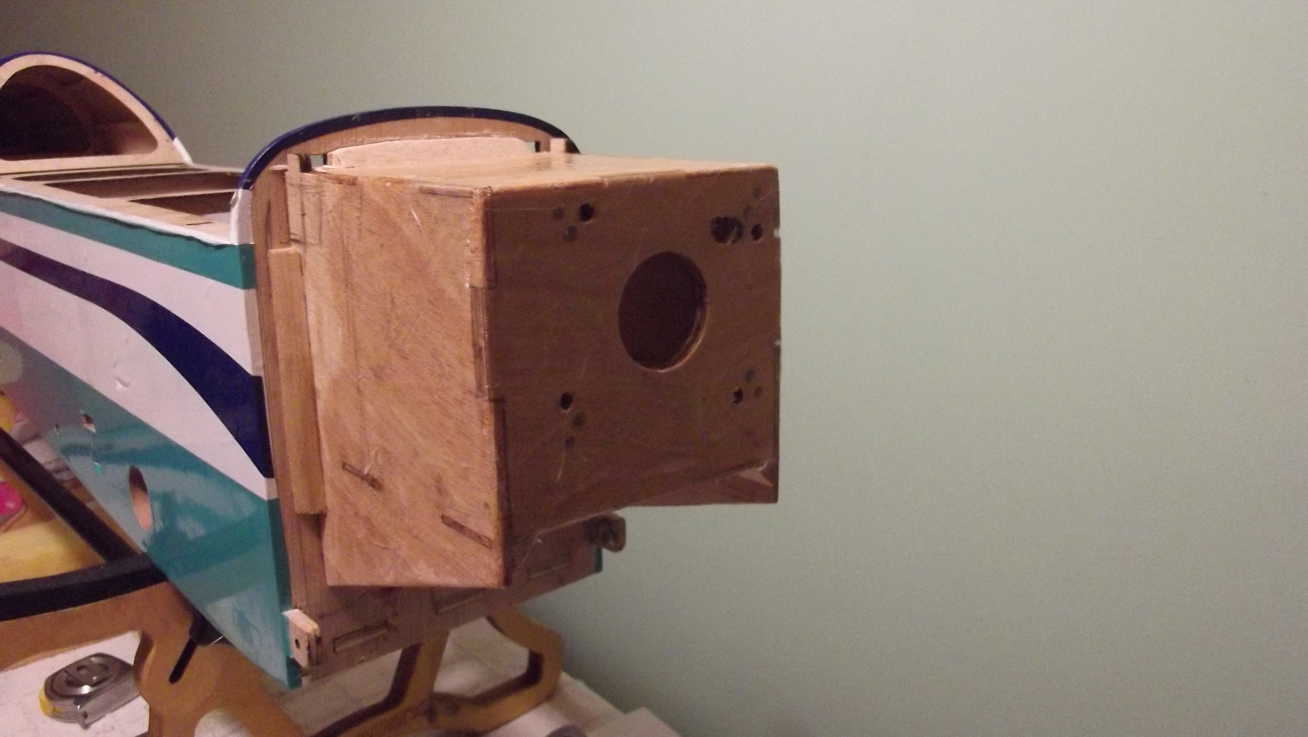

i now have a strong and light weight engine box and fuel proof at the same time.
02-28-2015 | 12:42 AM
#42
Thread Starter
Joined: May 2003
Posts: 286
Likes: 0
Received 0 Likes
on
0 Posts
From: GIBRALTAR (Europe) GX11 1AA
Well after all that hard work that i have had to go through with the engine box and fire wall is because the fire wall is just designed
to sit in front of the engine box,when normally most of all the models would be installed inside with grooved around the engine box
if this would have been the case i would have not had gone through all this.
Well this is what you get when the model has not been designed correctly,so and here we go now i have to get the under
carriage sorted too.i have also noticed that the blind nut are rusty or shall i say corroded just unbelievable.
Where has this model been to have the blind nuts corroded?
After having a good look at it there is no support to the wooden plate which holds the under carriage i am quite sure
if i don't re enforce it the wood will simply come of on my first landing.
here you have a snap shot off the ply wood.
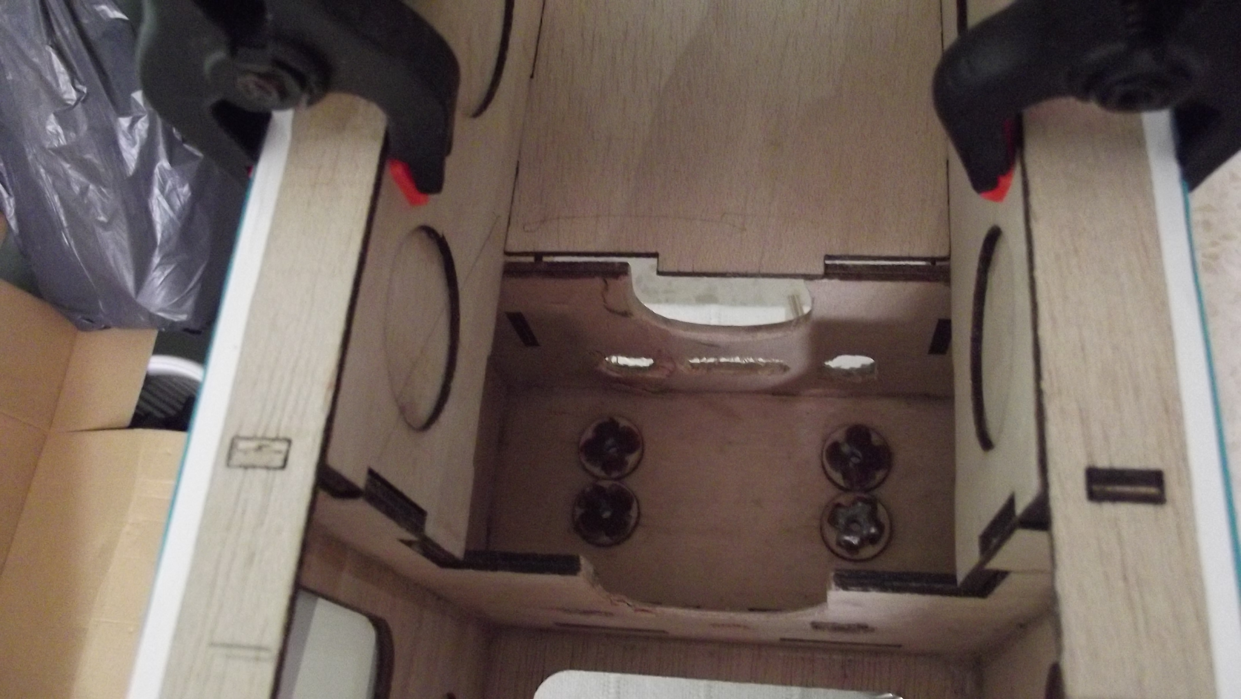
You can clearly see the corrosion on the blind nuts.
to sit in front of the engine box,when normally most of all the models would be installed inside with grooved around the engine box
if this would have been the case i would have not had gone through all this.
Well this is what you get when the model has not been designed correctly,so and here we go now i have to get the under
carriage sorted too.i have also noticed that the blind nut are rusty or shall i say corroded just unbelievable.
Where has this model been to have the blind nuts corroded?
After having a good look at it there is no support to the wooden plate which holds the under carriage i am quite sure
if i don't re enforce it the wood will simply come of on my first landing.
here you have a snap shot off the ply wood.
You can clearly see the corrosion on the blind nuts.
02-28-2015 | 12:59 AM
#43
Thread Starter
Joined: May 2003
Posts: 286
Likes: 0
Received 0 Likes
on
0 Posts
From: GIBRALTAR (Europe) GX11 1AA
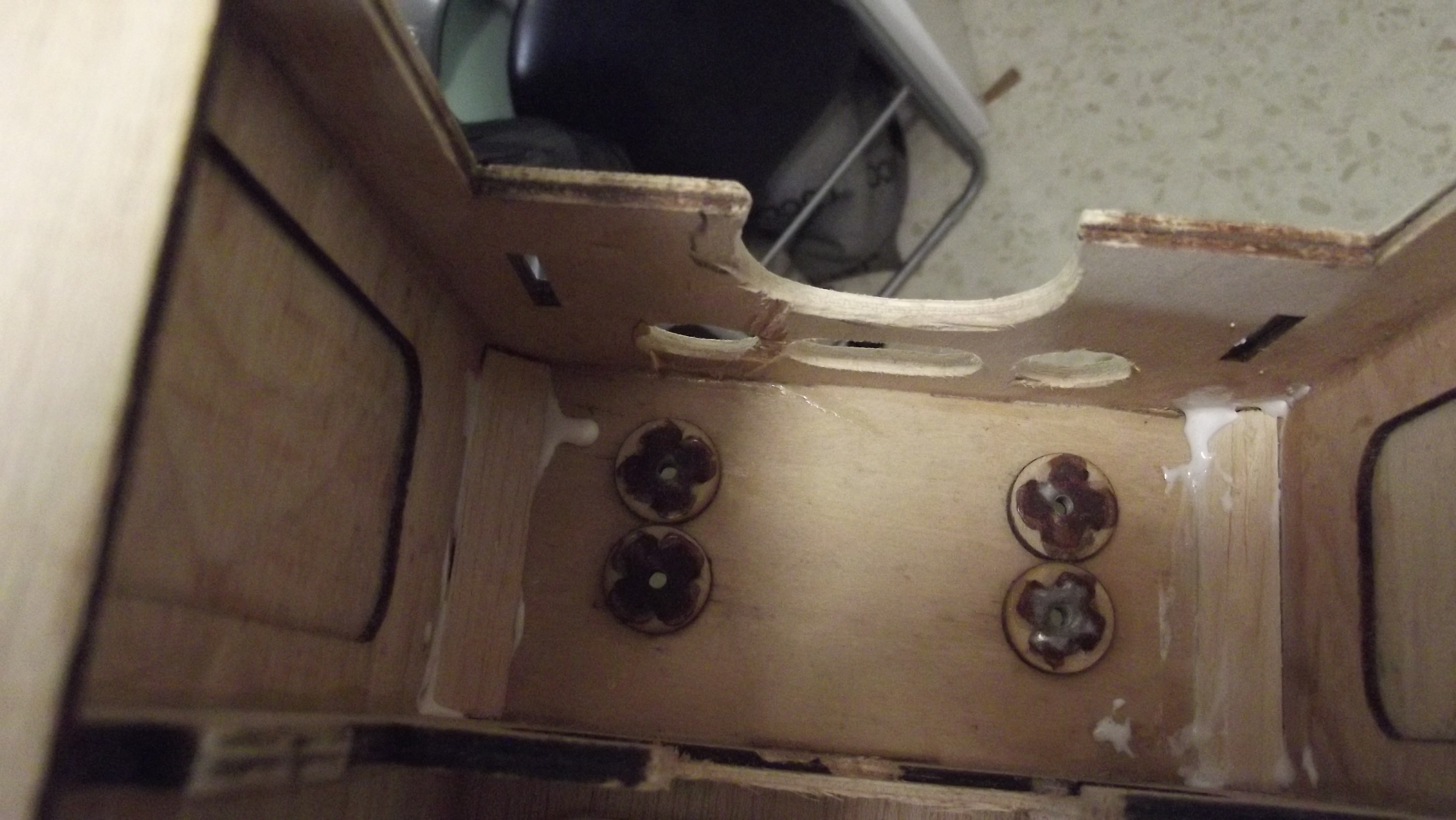
Ok let's get started with the re enforcement to the under carriage under side ply wood.
I first added two triangle balsa wood on both side in the inside of the fuselage with wood glue.
I went and turned the model over to the under side and cut out the covering material,i have to add i thought it states in the web site
from Glens Models that it's pro film or so i thought, well this on pro film or even oracover this is a cheap copy no where near pro film.
02-28-2015 | 01:24 AM
#44
Thread Starter
Joined: May 2003
Posts: 286
Likes: 0
Received 0 Likes
on
0 Posts
From: GIBRALTAR (Europe) GX11 1AA
I placed all round the inside edge of the under carriage again from balsa wood 4 cut outs of triangle
to help towards the re enforcement.
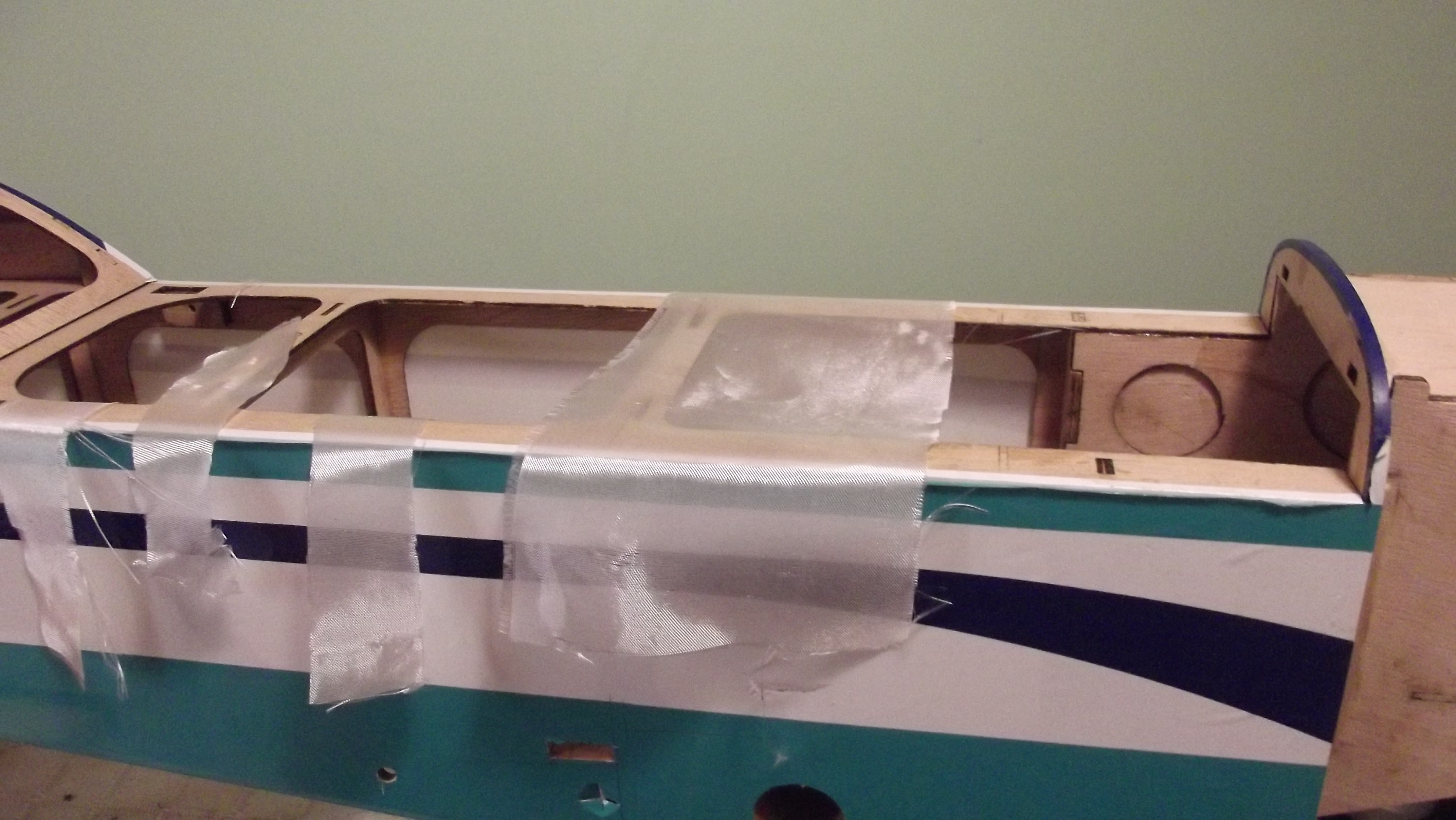
After getting the under side sorted i have prepared some trips of fiber glass and an elastic bandage this will help
on the flexibility of the impact when landing.specially at my flying site we fly off rough grounds on tar mark for as.
I covered the two blind nuts with paper tape after changing them as i was not to happy having them all full of rust.
the paper tape will prevent the epoxy getting inside the thread of the blind nut after epoxying it with the fiber glass cloth.
i also added to the strips of balsa wood no top of the bandage to help the two wood structures on the front
and rear of the fuselage where the tune pipe will be resting on.
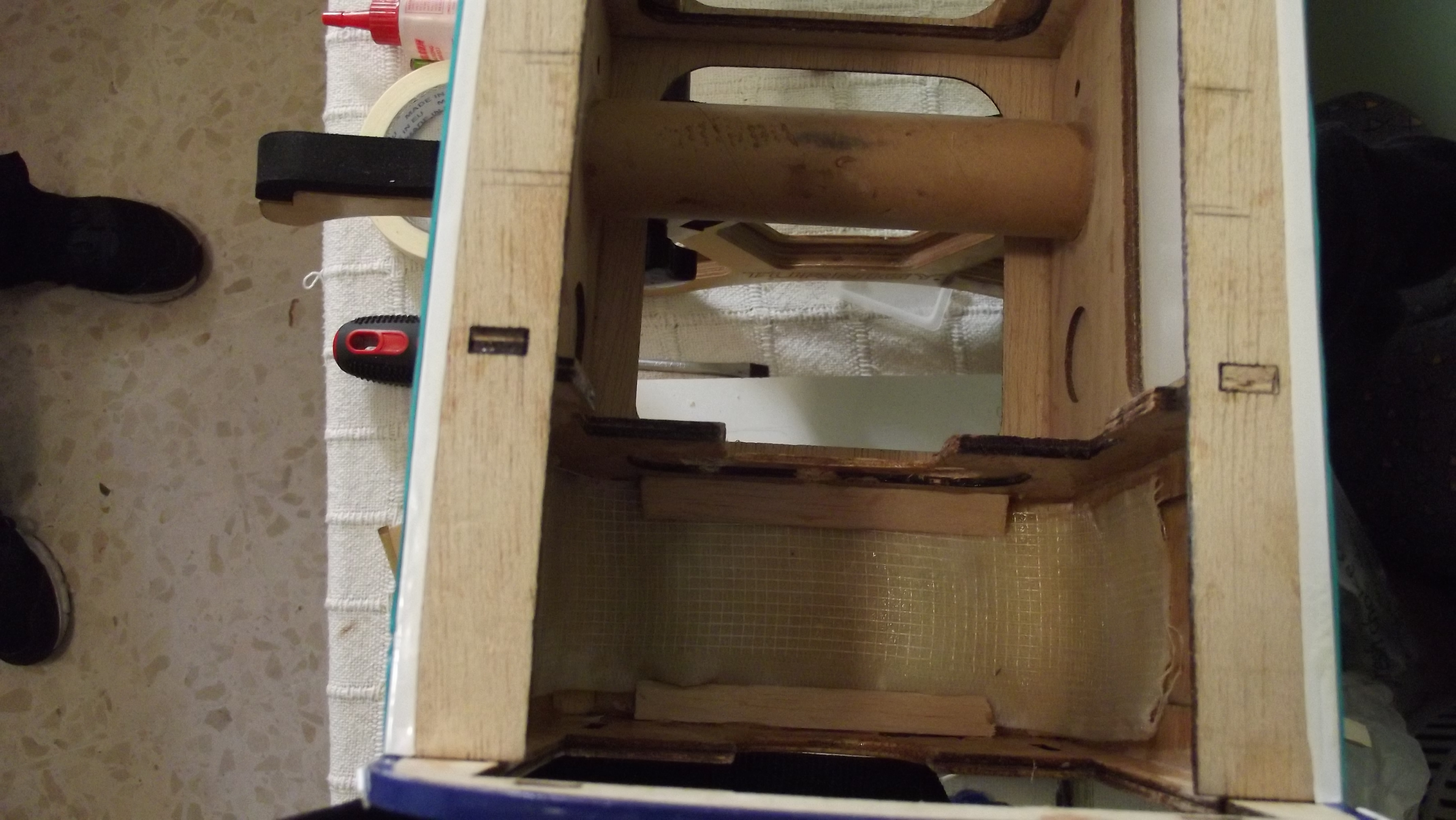
Under carriage sorted another thing out of the way.
to help towards the re enforcement.
After getting the under side sorted i have prepared some trips of fiber glass and an elastic bandage this will help
on the flexibility of the impact when landing.specially at my flying site we fly off rough grounds on tar mark for as.
I covered the two blind nuts with paper tape after changing them as i was not to happy having them all full of rust.
the paper tape will prevent the epoxy getting inside the thread of the blind nut after epoxying it with the fiber glass cloth.
i also added to the strips of balsa wood no top of the bandage to help the two wood structures on the front
and rear of the fuselage where the tune pipe will be resting on.
Under carriage sorted another thing out of the way.
02-28-2015 | 01:45 AM
#45
Thread Starter
Joined: May 2003
Posts: 286
Likes: 0
Received 0 Likes
on
0 Posts
From: GIBRALTAR (Europe) GX11 1AA
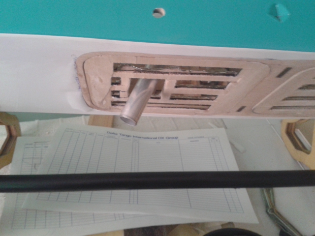
I am going to start sorting out the ventilation on the underside of the model for the exhaust manifold with
flexible tube and the canister.
At the under side of the model i cut round the holes to make way for the heat to get out from the inside of the fuselage.
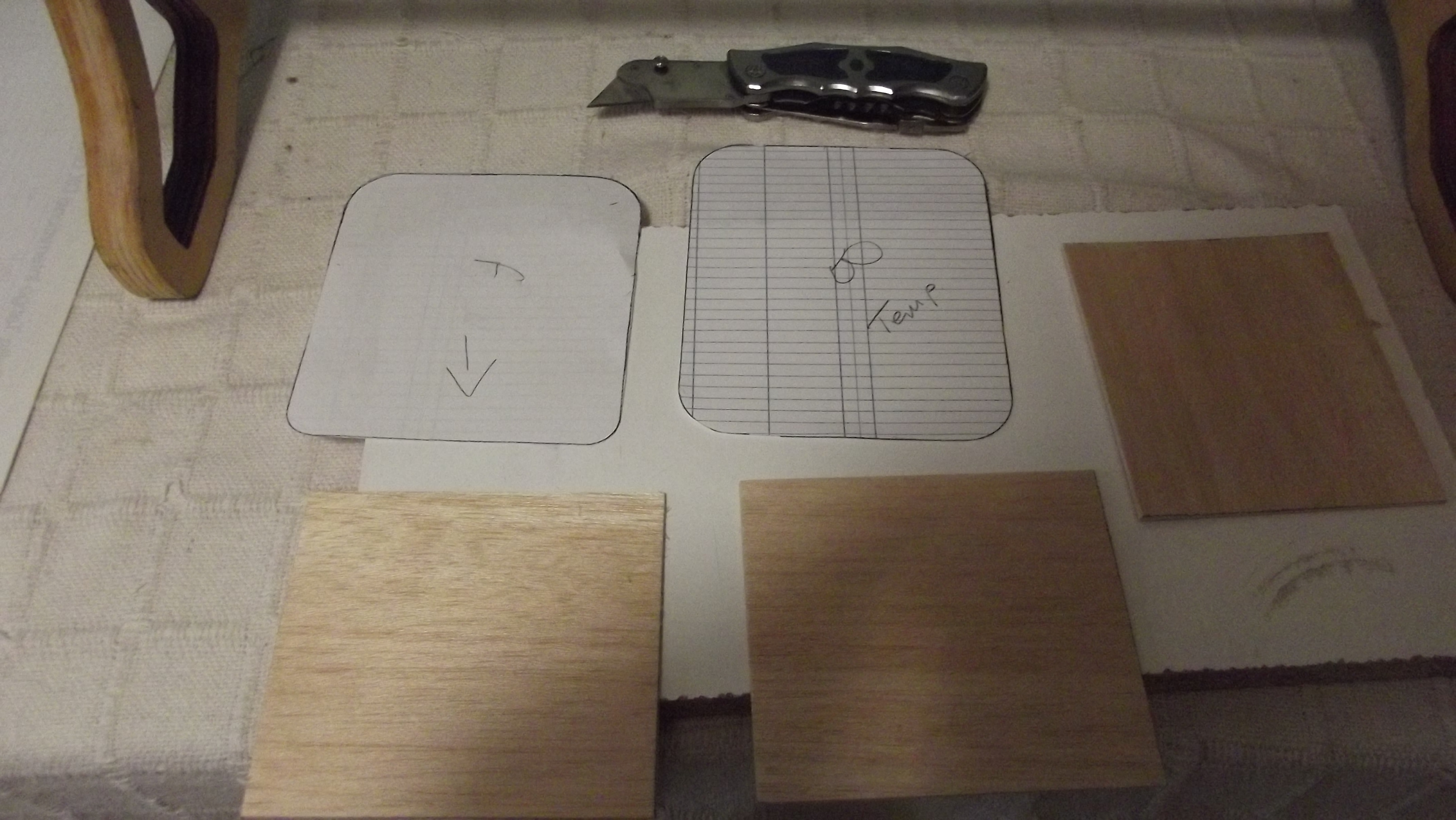
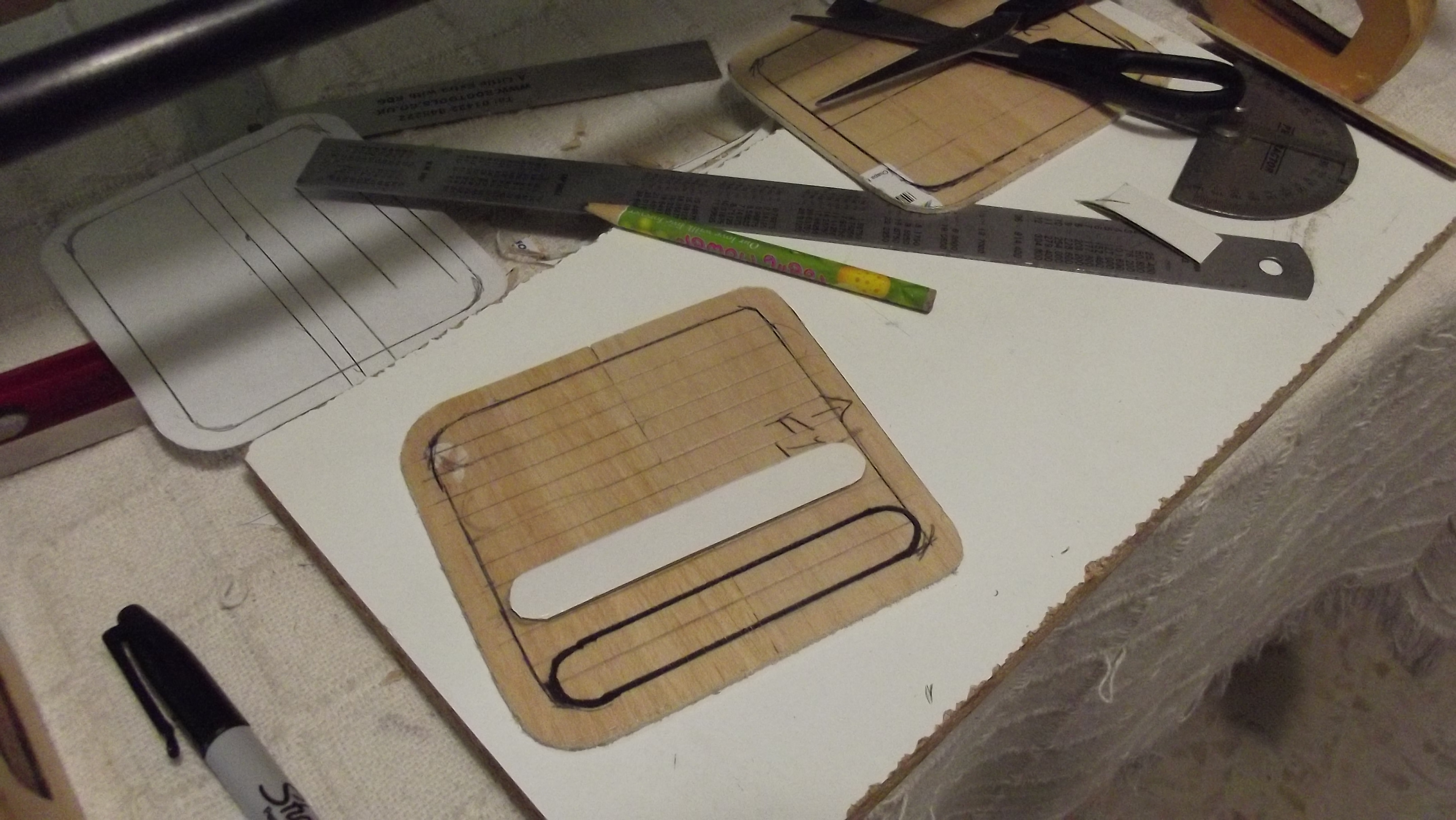
I made two different exact copy from some cut outs of card boards of the holes to make the vents as the two holes are not the same.

flexible tube and the canister.
At the under side of the model i cut round the holes to make way for the heat to get out from the inside of the fuselage.
I made two different exact copy from some cut outs of card boards of the holes to make the vents as the two holes are not the same.
02-28-2015 | 01:54 AM
#46
Thread Starter
Joined: May 2003
Posts: 286
Likes: 0
Received 0 Likes
on
0 Posts
From: GIBRALTAR (Europe) GX11 1AA
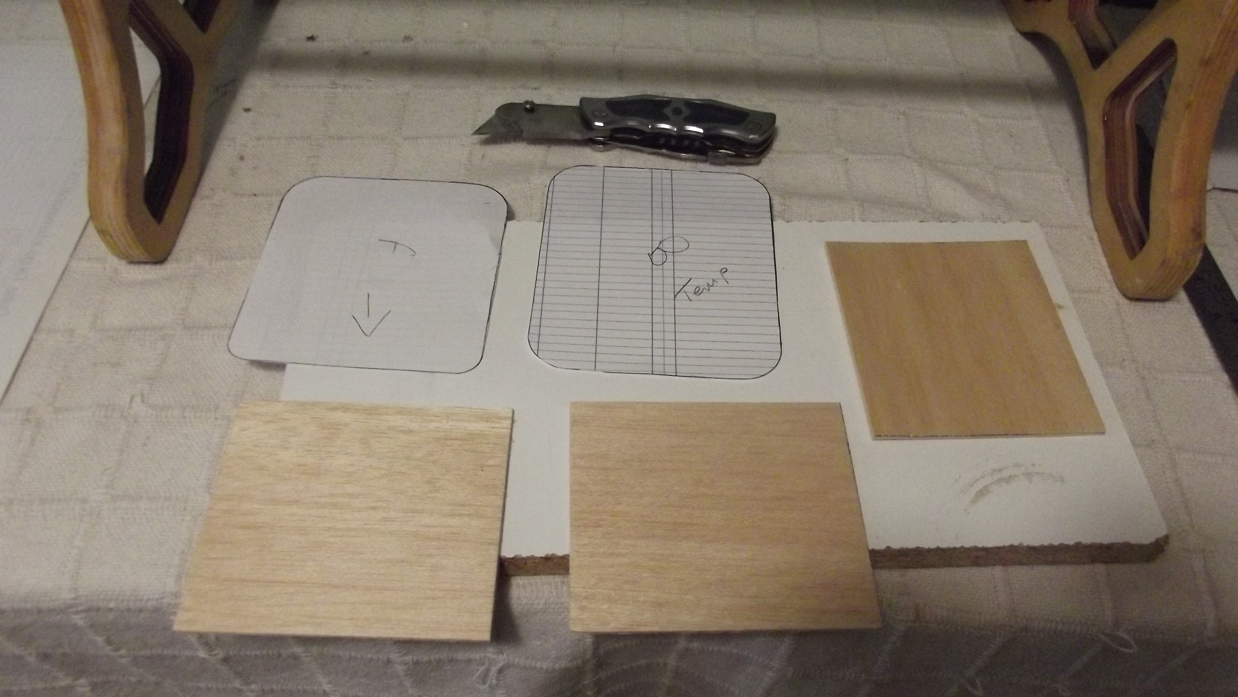
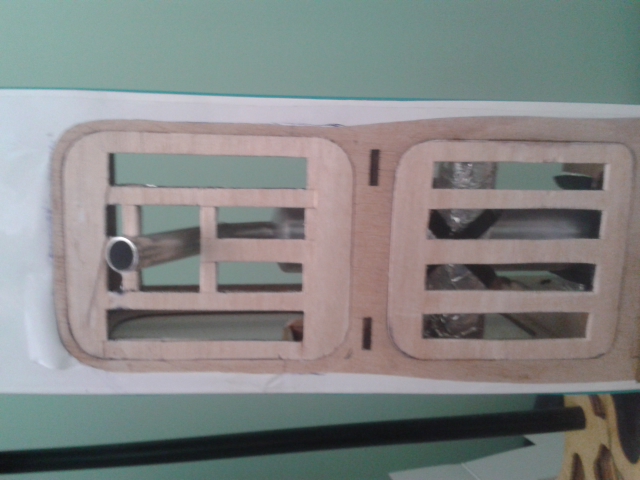
I dry fitted the two balsa wood cut outs and check it against the model underside holes.
I made the strips hole cut outs for the ventilation.
 Quite a task but well worth it you can see it in the end result.
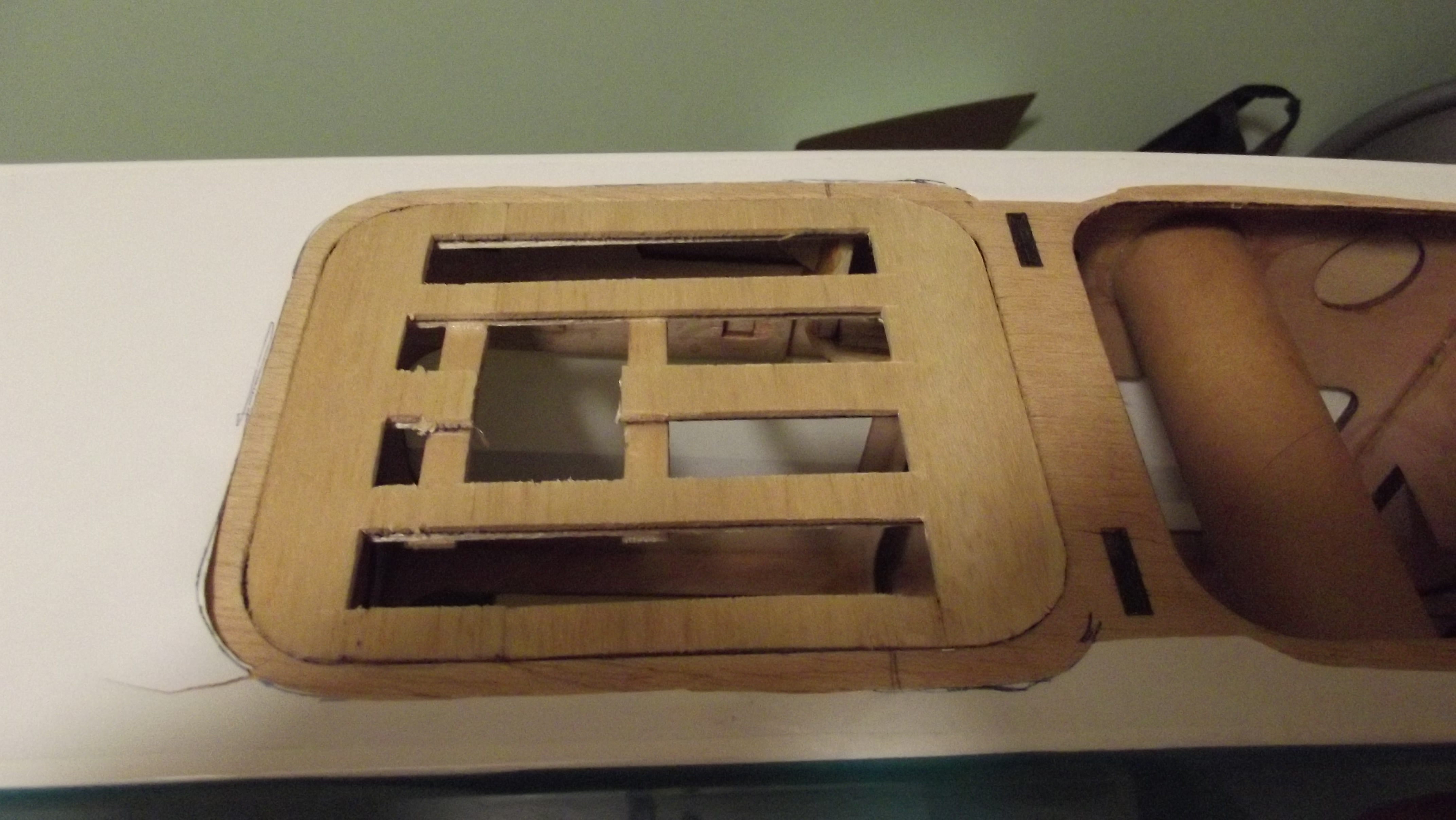
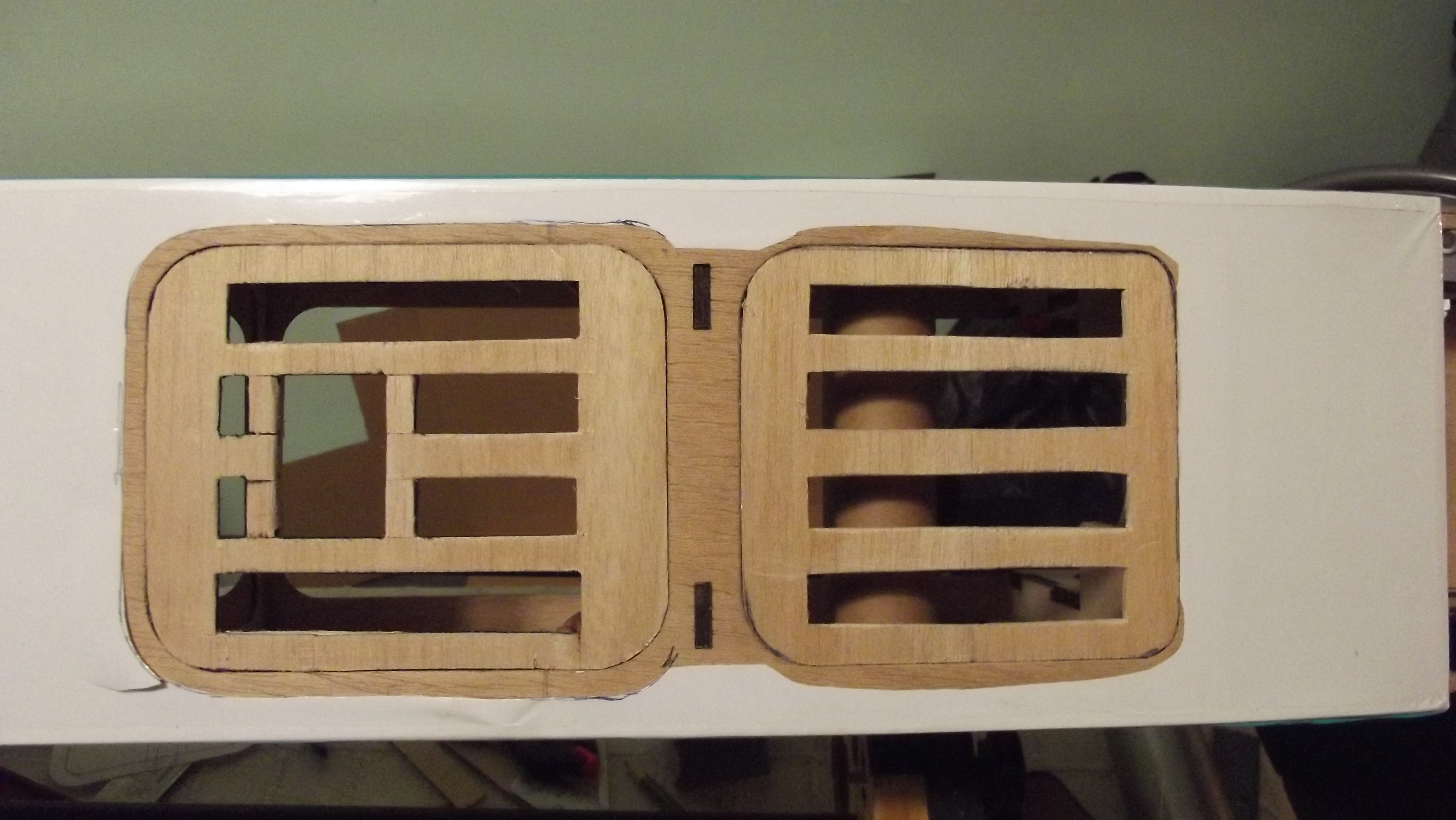
I made the strips hole cut outs for the ventilation.
02-28-2015 | 02:56 AM
#48
Thread Starter
Joined: May 2003
Posts: 286
Likes: 0
Received 0 Likes
on
0 Posts
From: GIBRALTAR (Europe) GX11 1AA
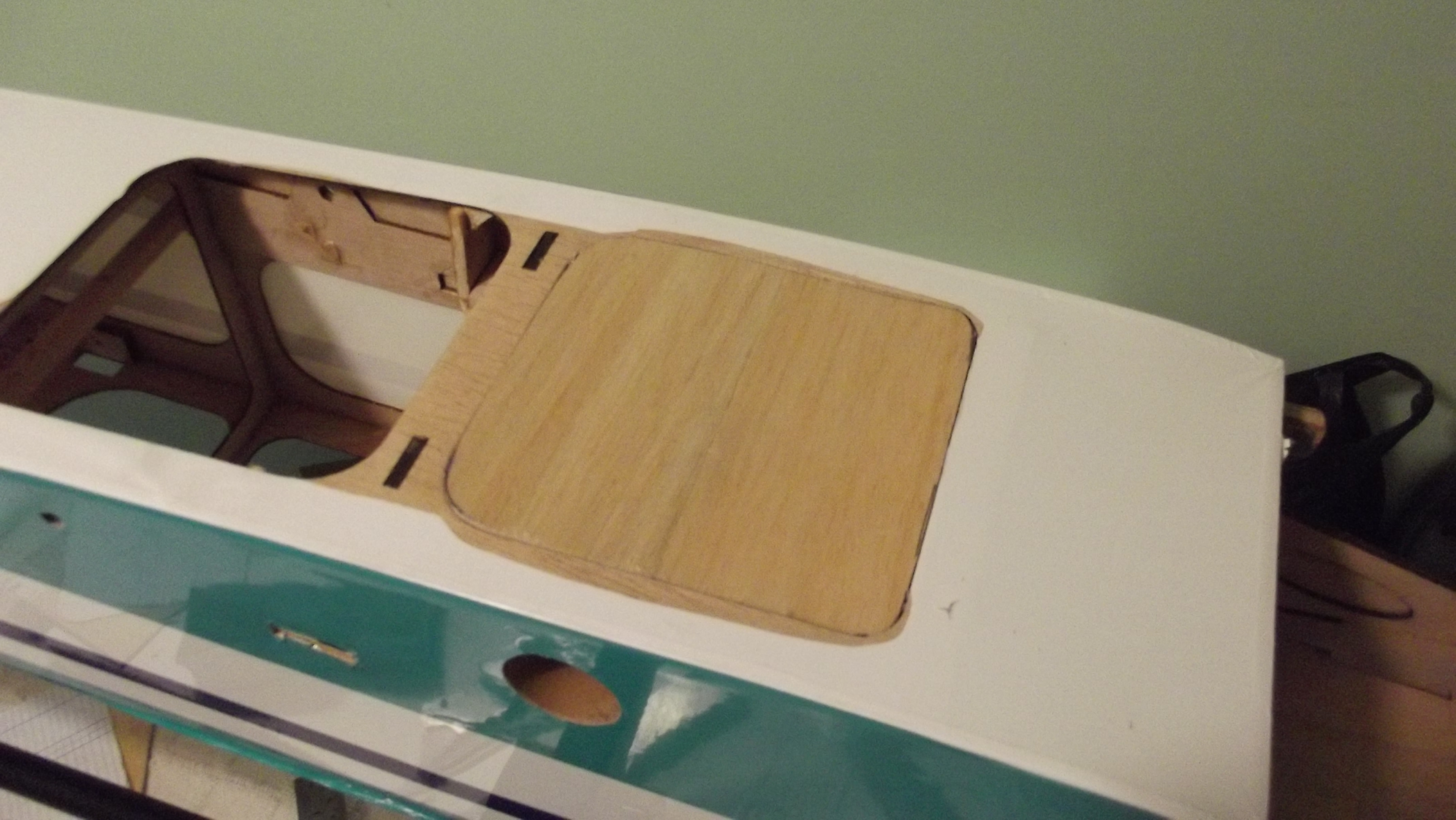
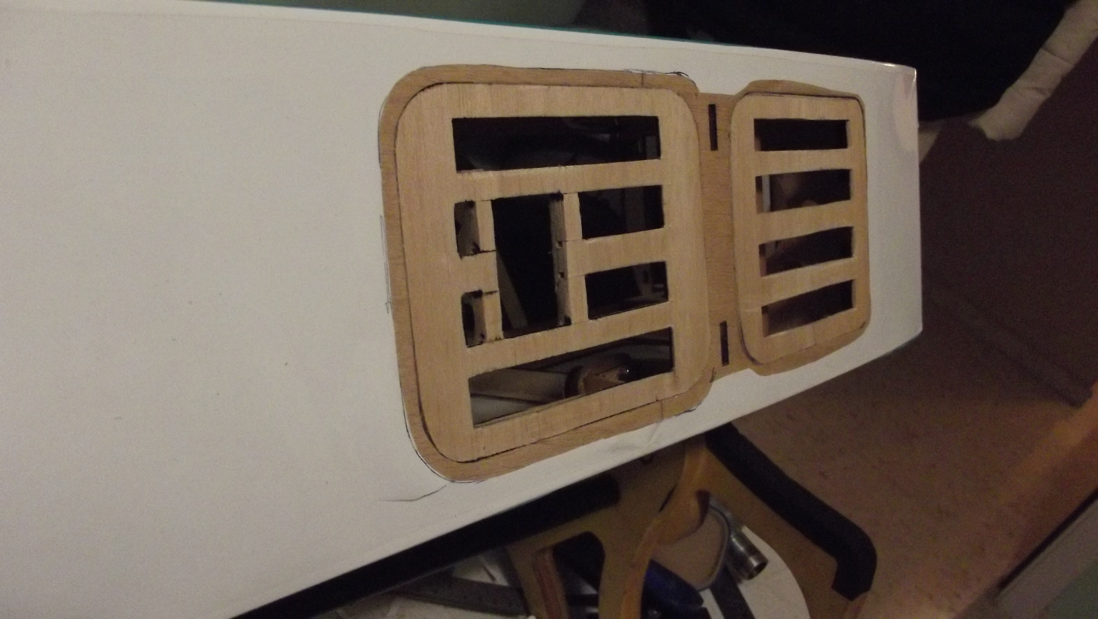
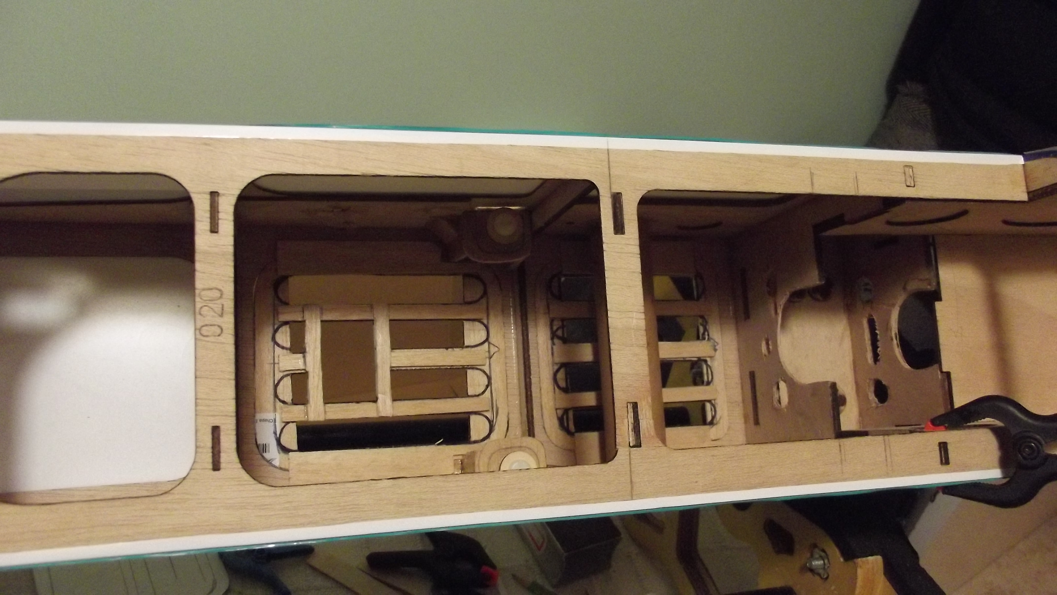
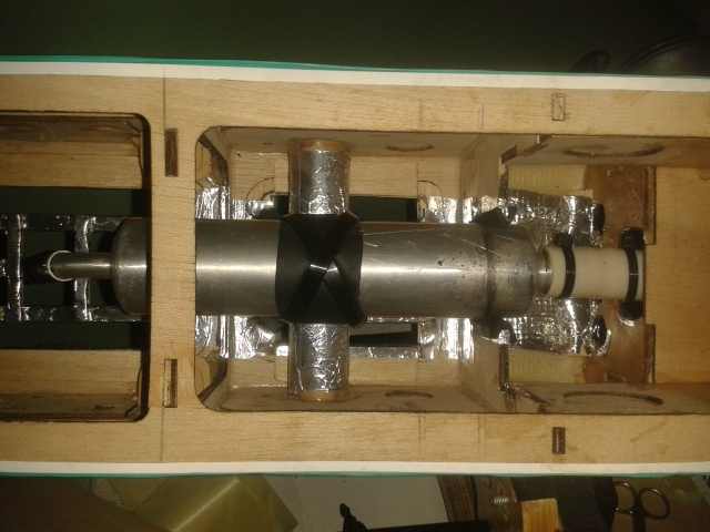
Here we go this is the part that we all like i suppose installing the goodies.
First thing is i have done is place inside the fuselage aluminium foil tape to protect the model from the heat produced
by the exhaust manifold with flexible tube and the canister.
I have started by installing the engine to the fire wall all screws are ti-tended with thread lock and spring washers.
as you can see i also added big washers to the fire wall so the studs from the engine mount dose not penetrate into the wood.

Hope you can see the foil in the inside of the model again to protect it from the heat if the canister.
First thing is i have done is place inside the fuselage aluminium foil tape to protect the model from the heat produced
by the exhaust manifold with flexible tube and the canister.
I have started by installing the engine to the fire wall all screws are ti-tended with thread lock and spring washers.
as you can see i also added big washers to the fire wall so the studs from the engine mount dose not penetrate into the wood.
Hope you can see the foil in the inside of the model again to protect it from the heat if the canister.
02-28-2015 | 03:05 AM
#50
Thread Starter
Joined: May 2003
Posts: 286
Likes: 0
Received 0 Likes
on
0 Posts
From: GIBRALTAR (Europe) GX11 1AA
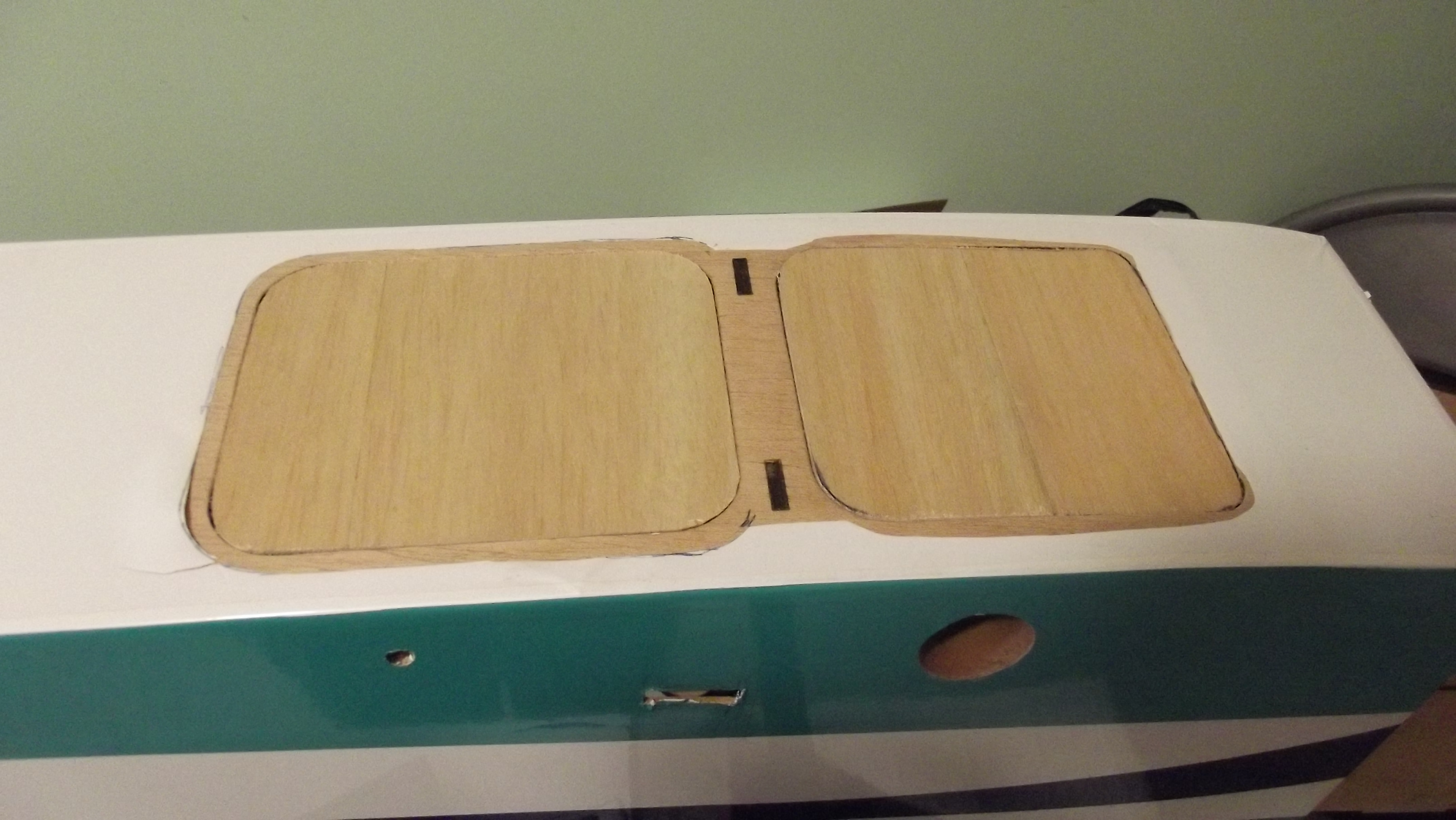
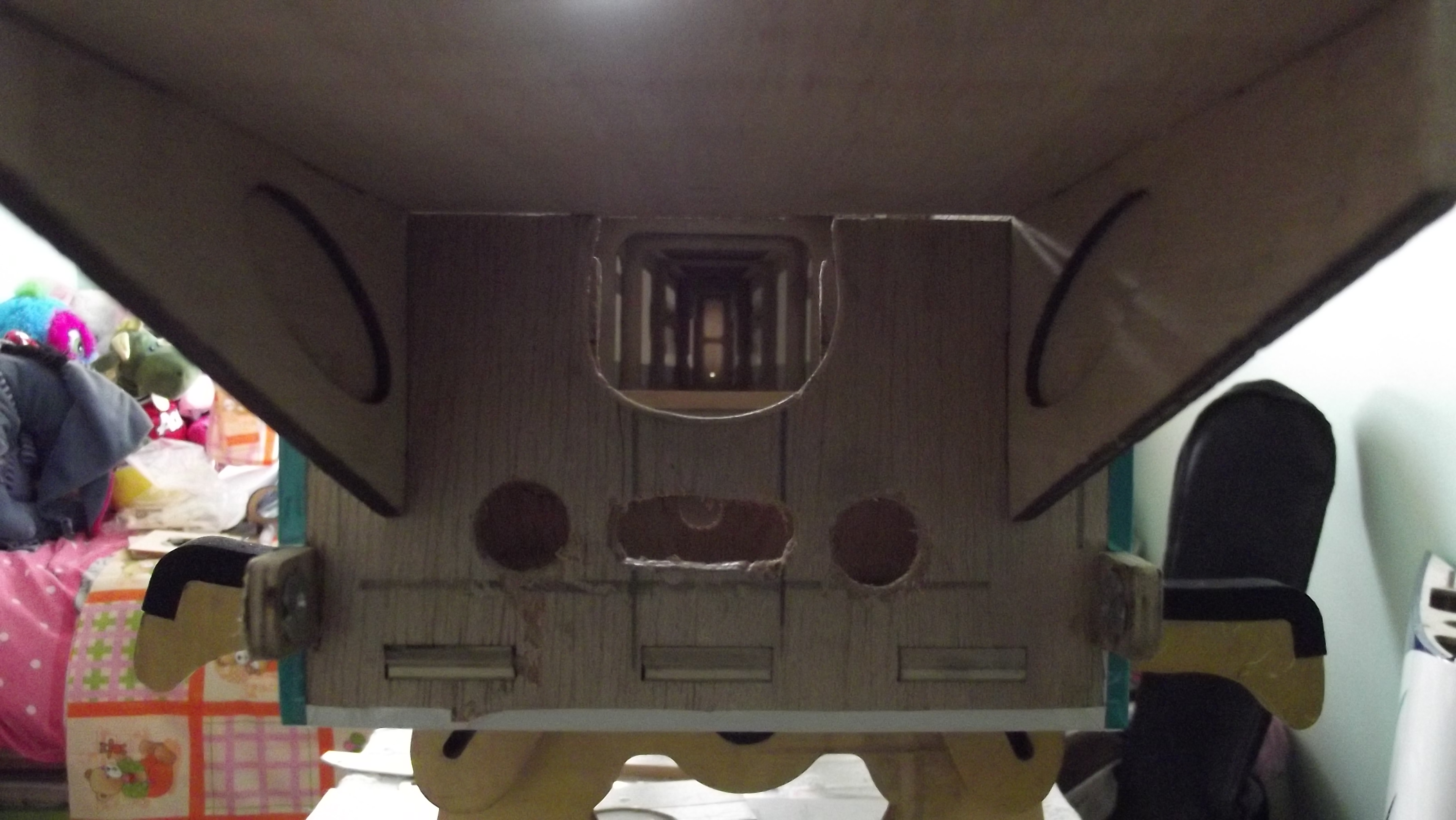
And here you can now see why i did that big square hole at the under side of the fuselage.
So there you go job done.
The next thing i need to do is to fasten the canister and box it all up so all the heat goes down and out,
all the holes i made in the front of the F2 and F3 is for the air flows out with the help of thrust coming from the prop.
Hope you all are enjoying the build well going to carry on with build will be shortly.
Thanks for watching.

