


Fancy a FunFactor 6061 ARO chassis?

 05-16-2006 | 10:46 PM
#27


My Feedback: (4)
Joined: Apr 2005
Posts: 2,327
Likes: 0
Received 0 Likes
on
0 Posts
From: Latrobe,
PA
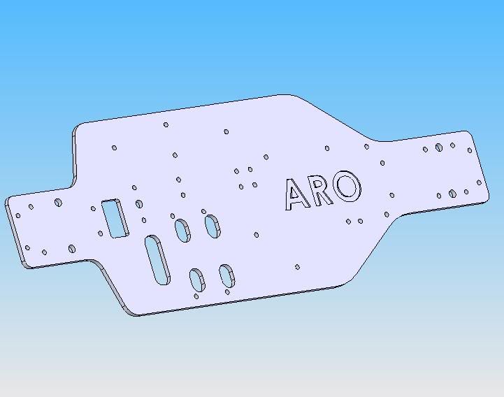
Here’s just a quick pic of the chassis. I still need to do the cutout’s on the other side… but I figure I will make one up before finalizing it. (I have the braces done, but they are going to change)
Hey Poor Judgment…
The front diff case holes were not centered on your drawing. Should they be? And should they be the same spacing as the rear diff mounting holes? Also, from your drawing, it looks like the front bend is a radius, or a two part bend… should it be? What is the angle of the bend?
FYI… The holes in the bottom of the chassis will be countersunk.
05-17-2006 | 08:32 AM
#28
Junior Member
Joined: Jan 2006
Posts: 11
Likes: 0
Received 0 Likes
on
0 Posts
From: , LA
This is great news and looks to be a great chassis. I just got a great deal on a Magnum chassis on ebay but will still buy one of these. Any luck of extending the chassis length to match the new magnum chassis. It's about a inche longer than the old, or maybe less.
05-18-2006 | 10:57 AM
#30

Senior Member
Joined: Jul 2003
Posts: 244
Likes: 0
Received 0 Likes
on
0 Posts
From: birmingham, UNITED KINGDOM
looking good Tony!
The bend looks like its only a one part bend... I can get some pictures if you like but looking at the inside of the bend you can see the tool mark where it was bent and theres only the one (if that makes any sence) the inside of the bend is sharp while the outside its quite curved [&:]
my cens in bits so I will take another look later
05-18-2006 | 11:57 AM
#31
My Feedback: (4)
Joined: Apr 2005
Posts: 2,327
Likes: 0
Received 0 Likes
on
0 Posts
From: Latrobe,
PA
Craigb…
Thanks. A couple of close-up pics would be helpful. I’m going to bid on a used FF on ebay today… so I may have one to actually do some test fitting of parts. One more thing… if you have anyway to get a good measurement from the sharp inside bend to the front diff mounting holes… that would help me out a lot.
Thanks. A couple of close-up pics would be helpful. I’m going to bid on a used FF on ebay today… so I may have one to actually do some test fitting of parts. One more thing… if you have anyway to get a good measurement from the sharp inside bend to the front diff mounting holes… that would help me out a lot.
05-18-2006 | 01:21 PM
#32
Senior Member
Joined: Jul 2003
Posts: 244
Likes: 0
Received 0 Likes
on
0 Posts
From: birmingham, UNITED KINGDOM
Grrr seems my dad stole my camera [:@]
I tryed taking some with my webcam... seems OK quality
after looking at it now it seems there is a slight inside curve but its not needed as the diff case has a sharp bend[:-]
ill try find the angles but heres the pics
I tryed taking some with my webcam... seems OK quality
after looking at it now it seems there is a slight inside curve but its not needed as the diff case has a sharp bend[:-]
ill try find the angles but heres the pics
05-22-2006 | 12:56 PM
#34
Thread Starter
Senior Member
Joined: Apr 2004
Posts: 2,077
Likes: 0
Received 0 Likes
on
0 Posts
From: Cleethorpes, UNITED KINGDOM
Hey Poor Judgment…
The front diff case holes were not centered on your drawing. Should they be? And should they be the same spacing as the rear diff mounting holes? Also, from your drawing, it looks like the front bend is a radius, or a two part bend… should it be? What is the angle of the bend?
The front diff case holes were not centered on your drawing. Should they be? And should they be the same spacing as the rear diff mounting holes? Also, from your drawing, it looks like the front bend is a radius, or a two part bend… should it be? What is the angle of the bend?
The diff case measurements are just as I took them from the chassis, I didnt actually check to see what they came out at tbh. Or have I snapped onto the wrong point when drawing them in...?
Im guessing u are ok now with u having a diff to work from - or would u still like a revised drawing? its not a problem if u do. unsure if the rear is exactly the same hole spacing as the front, due to my chassis being half built up at the mo! Lol, I can pull it apart and check if u like tho?
That front bend is 30 degrees on my JT chassis iirc, I think I added that as a note on the email with the drawing attached. My stock cen one is slightly under 30 degrees - I put that down to wear and tear. Its a single point bend with the bend fulcrum point shown, I think, on the drawing I sent. I have the version here that I mean, if I sent a different one - would u like it sending?
I drew the bend as it is, rather than as a true contruction drawing, apols for any confusion there. Worth bearing in mind re the inner radius tho, for the diff casings, a sharp corner there on the cases wont let them fit properly.
05-22-2006 | 02:44 PM
#35
My Feedback: (4)
Joined: Apr 2005
Posts: 2,327
Likes: 0
Received 0 Likes
on
0 Posts
From: Latrobe,
PA
Hey Poorjudgment…
Not a problem. I understand. I’ve also been very busy with my day job (travel) and with the preparations of a new baby. At the moment, I don’t need you to revise the drawing. Since I have a front case… I moved the holes to center, and in the correct spot. I don’t know if the conversion process moved the holes, (2D to 3D) or if you saved it that way. Either way, it’s not a big deal.
To all…
I’m going to try to do the CAM code tonight… and if the 6061 stock shows up… I should have the first one cut in a few days. I will post pictures soon
05-22-2006 | 06:49 PM
#36
Senior Member
There are a few holes in that photo that aren't needed. I am not sure if Poor Judgement added them after he received the chassis or if he purchased it that way.
In my opinion the fewer the holes the better.
Would it be possible to get a chassis with the marked holes omitted?
And maybe a 1/2"- 1" inch wider? Preferably 1".
rolland
In my opinion the fewer the holes the better.
Would it be possible to get a chassis with the marked holes omitted?
And maybe a 1/2"- 1" inch wider? Preferably 1".
rolland
05-22-2006 | 08:25 PM
#37
Senior Member
Joined: Jun 2005
Posts: 104
Likes: 0
Received 0 Likes
on
0 Posts
From: Cambridgeshire, UNITED KINGDOM
Ive noticed that the chassis hasnt got the bends on the sides as the original one had. This would have given the chassis lots of extra strength against flex from head on crashes or badly landed jumps that maycause the centre driveshaft to bend and also they keep out some of the dirt. I know the JT one hasnt got them but just thought i would mention it before they are made.
05-22-2006 | 08:41 PM
#38
Senior Member
Joined: Jul 2003
Posts: 244
Likes: 0
Received 0 Likes
on
0 Posts
From: birmingham, UNITED KINGDOM
I recon the JT and this new chassis will be somewhat thicker and made of stronger stuff then the cen chassis.
Just wonderd I wouldnt mind one for my cen fourstoke once i get it all debugged[8D] would it be possible Tony to have the engine holes moved to where i want them for my chassis or would it be alot of trouble?
Just wonderd I wouldnt mind one for my cen fourstoke once i get it all debugged[8D] would it be possible Tony to have the engine holes moved to where i want them for my chassis or would it be alot of trouble?
05-22-2006 | 11:33 PM
#39
Senior Member
My Feedback: (1)
Joined: Apr 2005
Posts: 1,713
Likes: 0
Received 0 Likes
on
0 Posts
From: _,
AB, CANADA
ORIGINAL: rolland
There are a few holes in that photo that aren't needed. I am not sure if Poor Judgement added them after he received the chassis or if he purchased it that way.
In my opinion the fewer the holes the better.
Would it be possible to get a chassis with the marked holes omitted?
And maybe a 1/2"- 1" inch wider? Preferably 1".
rolland
05-23-2006 | 03:52 AM
#40
Thread Starter
Senior Member
Joined: Apr 2004
Posts: 2,077
Likes: 0
Received 0 Likes
on
0 Posts
From: Cleethorpes, UNITED KINGDOM
The 4 for the battery box as mentioned, are probably best left in my opinion. The 2 together near the centre are for my extra toplate upright. The three in a line below that are fuel tank mount holes for the mugen mst-1 tank or the stock cen tank. And the single hole at the bottom is JTs position for the exhaust hanger (Idont use it, its way out...). We need the fuel tank holes tho, and if this is just a prototype... could we leave the others in too for now? 
I like the idea of the chassis edges being bent up tho, it would just about cure all flex issues very simply. Thatd mean much less stress on other parts... sounds good to me - do you have facilities to bend up 1/2" or so extra on each side?
I like the idea of the chassis edges being bent up tho, it would just about cure all flex issues very simply. Thatd mean much less stress on other parts... sounds good to me - do you have facilities to bend up 1/2" or so extra on each side?
05-25-2006 | 01:16 PM
#41
My Feedback: (4)
Joined: Apr 2005
Posts: 2,327
Likes: 0
Received 0 Likes
on
0 Posts
From: Latrobe,
PA
Hi Guys,
OK… Since we are still in the prototype stages… I can make any changes you guys may want. If the overall consensus is that fewer holes are needed… then that’s what we will do. But… I feel the extra holes will allow more people to use this chassis since it will allow for more options (like other fuel tanks) and the usage of stock parts. (like the battery box) The extra holes in the chassis will not make it any weaker with the type of alloy being used. And… it will make it a bit lighter overall. (for better performance)
As far as the bends in the sides… I will need to buy a bending break to do them. But, I’m willing to buy it if there really is enough interest in these chassis. But, I don’t think it will cure the flexing problem. The old RC10 use to have sides that were bent up, and on a hard impact it would just bend at the nose or the tail. (outside of the bends) Adding the bends will just add weight, and cost to the chassis. (more metal needed to make it happen) Lastly on the bends, or just adding width to the chassis… it will make it hard for anyone to use a narrow buggy body. (just a random thought)
My last thoughts are…
We can make multiple versions of this chassis to allow for bends, holes for different engines, etc. But that will cause the price to be higher since I will have to make CAD drawings, CNC programs, and tooling fixtures for each of the designs. I am willing to do it… but I think if we can agree to one design… it would be better for every one.
Now... I think that there should be a set of holes for a “Big block” or four-stroke. But that’s just my opinion.
If you have any ideas… post them… and we can all vote on them before I start cutting metal. (rejected prototypes still cost me)
05-25-2006 | 01:51 PM
#42
Thread Starter
Senior Member
Joined: Apr 2004
Posts: 2,077
Likes: 0
Received 0 Likes
on
0 Posts
From: Cleethorpes, UNITED KINGDOM
big block 2 strokes will work with the stock holes.
craigb is ur man re the 4 strokes holes.
the JT chassis works pretty well without the bends on the sides. it would be more rigid, i feel, but maybe not worth that small amount for the weight increase involved...? im easy either way tbh.
craigb is ur man re the 4 strokes holes.
the JT chassis works pretty well without the bends on the sides. it would be more rigid, i feel, but maybe not worth that small amount for the weight increase involved...? im easy either way tbh.
05-25-2006 | 01:53 PM
#43
Senior Member
Joined: Jul 2003
Posts: 244
Likes: 0
Received 0 Likes
on
0 Posts
From: birmingham, UNITED KINGDOM
Tony-
It would be great if you can leave the spur gear clearance hole uncut but instead just milled!
I have a mt2 and the spurs only need about 1mm of clearance or so... all other cens i have seen are the same. blocking this hole will give the spurs loads of protection from dirt and make them last mucho longer
05-25-2006 | 01:55 PM
#45
Senior Member
My Feedback: (1)
Joined: Apr 2005
Posts: 1,713
Likes: 0
Received 0 Likes
on
0 Posts
From: _,
AB, CANADA
Why not set up a few threads with polls for FF owners to see what people think. Just to see how many people are using what tanks, batt boxes etc. so that we know what holes are necessary. I know azzman did a write up on using 125cc ofna tanks so I would imagine a few ppl read that and used it like I did.
05-25-2006 | 10:24 PM
#46
Senior Member
Joined: Jun 2005
Posts: 104
Likes: 0
Received 0 Likes
on
0 Posts
From: Cambridgeshire, UNITED KINGDOM
I agree with Dr H on the subject of the holes. The more the better. if you dont need them then you can always fill them with something there are plenty of "liquid metals" about. As for the clearence holes my MT2 gears come nearly flush with the bottom of the chassis and my rally is lower still so i would need that hole there. if your worried about dirt and stuff getting into the spurs then get some left over plastic from bodyshells and fix to the bottom of the chassis. Hpi MT2 chassis come with a part moulded specificically for this and fit the FF pretty well.
05-26-2006 | 05:12 PM
#47
Senior Member
Some of the holes that I marked are needed for some of the stock componets. They weren't the ones that aren't need. The reason I asked is for a project that I have in mind and I will not need them and they could possibly be in the way.
I think the extra width would be nice for fitting aftermaket fuel tanks and Rx/bat boxes and a 1/2 inch on each side won't interfere with the body. If anything it will seal it up better.
Having the sides bent really isn't necessary the JT chassis flexes very little. Remember this is a one piece chassis that is going to be nearly twice as thick as stock, the majority of flex from the stock chassis is from where the front bolts on to the rest of the chassis.
The holes for the spurs need to be left. It would be more damaging to spur gears if it is removed. I will take a much smaller rock to strip them.
The one thing that I would really like to see is the extra width. I can deal with anything else, especially since it won't be anodized and I can weld the holes closed if I need to.
Does anyone know how long the center dog bone is on the Magnum? If it is only a couple of mm's it might not be worth it to have a chassis to accomodate the Magnums center dog bone. But the extra length would be nice.
rolland
05-27-2006 | 08:46 PM
#48
Thread Starter
Senior Member
Joined: Apr 2004
Posts: 2,077
Likes: 0
Received 0 Likes
on
0 Posts
From: Cleethorpes, UNITED KINGDOM
http://www.rcuniverse.com/forum/m_42...tm.htm#4219795
there u go
1. Could you tell me how much longer the chassis' are than the stock Funfactor, and whereabouts in the chassis is the length added?
2. Do the Magnum etc use the same centre shaft as the Funfactor?
2. Do the Magnum etc use the same centre shaft as the Funfactor?
1.) 1 1/2" Longer than the stock Fun Factor.
2.) No, the center shaft is 1 1/2" longer than the Fun Factor
2.) No, the center shaft is 1 1/2" longer than the Fun Factor
05-28-2006 | 10:51 AM
#50
Thread Starter
Senior Member
Joined: Apr 2004
Posts: 2,077
Likes: 0
Received 0 Likes
on
0 Posts
From: Cleethorpes, UNITED KINGDOM
no probs.
i can see the advantages of a longer chassis, it just means buyers would need a longer shaft too. ill take a chassis either way, but others may be put off. there hasnt been a huge amount of interest in it after all, then again, the hexes seemed to sell pretty well... (slides off to check ebay for cen centre shafts)
i can see the advantages of a longer chassis, it just means buyers would need a longer shaft too. ill take a chassis either way, but others may be put off. there hasnt been a huge amount of interest in it after all, then again, the hexes seemed to sell pretty well... (slides off to check ebay for cen centre shafts)

