


Building a scale 1973 Pay'N Pak from plans
 05-29-2021 | 09:21 PM
#1

Thread Starter

Years ago, I built a sport 20 Pay'N Pak, starting with a Dumas kit. Since I didn't want to build it using the die "crushed" mahogany framing, I spent several weeks reworking parts and changing into a hull that would work. I even documented the process in a thread linked below:
Re-Engineering A Dumas Pay'N Pak - RCU Forums (rcuniverse.com)
At the request of a new builder from the land down under, I've agreed to do a thread on building a 1/8 scale 1973 Pay'N Pak. Like the sport 20 from last time, I will be making several changes from the plans based on measurements taken from the full sized boat, presently on display at the Hydroplane & Raceboat Museum in Kent Washington.
Before I actually get started on the build, I'm going to give a bit of information on the plans. The plan set was originally drawn by Roger Newton as the 1974 Miss Cotts Beverage. The full sized boat was originally the 1972 Notre Dame, so changing the plans to make any one of 39 similar boats was basically changing the color sheet that showed the paint scheme and the configuration of the cockpit, cowling and tail arrangement. The "Pak" was the fourth plan set drawn and was, however, different than the rest. The designer, Ron Jones, made FIVE major changes when he started working on the "Pak" from the previously built Notre Dame:
Now, it's time to start the build.
The first change is the bottom of the sponson insides. Using measurements taken off of the full sized boat, the depth of the sponsons has been reduced from the plan depth and the air traps reshaped to match the full sized boat.
Change number 2 is the height of the transom and the deck shape of the rear of the boat. The plans have the transom shorter than the scale height. The transom on the full sized boat is 13" high, thus making the scale transom 1.625"(41.275mm), .25"(6.35mm) taller than shown on the plans. This requires redrawing the top of the engine bay walls and the sponson insides to make the corrected transom fit properly.
Change number three is I have to move a full width cross frame forward roughly an inch(25.4mm) to get the firewall at the rear of the engine bay into it's correct scale location and add a second bulkhead at the front of the engine bay where there is one on the full sized boat that supports a large oil tank used for the lubrication system in the Rolls Royce Merlin that powered the boat.
One change that I didn't have to make was the bottom of the engine bay walls. I went with a 4 degree rise at the rear of the airtrap section of the sponson insides which, surprisingly, matched the plans. It was also very close to the full sized boat which has a 5 degree rise.
Now that I've bored you all to death, it's time to cut out the lengthwise frames and add stringers to the bottom of them so there will be more to glue the bottom to. Pictures to come within the next few days
Re-Engineering A Dumas Pay'N Pak - RCU Forums (rcuniverse.com)
At the request of a new builder from the land down under, I've agreed to do a thread on building a 1/8 scale 1973 Pay'N Pak. Like the sport 20 from last time, I will be making several changes from the plans based on measurements taken from the full sized boat, presently on display at the Hydroplane & Raceboat Museum in Kent Washington.
Before I actually get started on the build, I'm going to give a bit of information on the plans. The plan set was originally drawn by Roger Newton as the 1974 Miss Cotts Beverage. The full sized boat was originally the 1972 Notre Dame, so changing the plans to make any one of 39 similar boats was basically changing the color sheet that showed the paint scheme and the configuration of the cockpit, cowling and tail arrangement. The "Pak" was the fourth plan set drawn and was, however, different than the rest. The designer, Ron Jones, made FIVE major changes when he started working on the "Pak" from the previously built Notre Dame:
- The transom at the back of the boat was flat topped while every other boat was arched upward a few inches in the center
- The hull and all of the framing was built primarily from 1" thick aluminum honeycomb instead of wood. Only the deck and curved sponson skins were made from plywood with fiberglass on top
- The cockpit, cowling and tails were welded aluminum instead of the normal molded fiberglass
- Instead of a single centerline vertical tail faired into the cockpit, he installed twin vertical tails with a horizontal wing mounted on top
- The cockpit was going to be in front of the engine in the now common "cabover" configuration. This last part was vetoed by the person buying the boat, Dave Heerensperger, due to the fact that it didn't work on the previous twin "Hemi" powered 1970 Pak, but that's another story
Now, it's time to start the build.
The first change is the bottom of the sponson insides. Using measurements taken off of the full sized boat, the depth of the sponsons has been reduced from the plan depth and the air traps reshaped to match the full sized boat.
Change number 2 is the height of the transom and the deck shape of the rear of the boat. The plans have the transom shorter than the scale height. The transom on the full sized boat is 13" high, thus making the scale transom 1.625"(41.275mm), .25"(6.35mm) taller than shown on the plans. This requires redrawing the top of the engine bay walls and the sponson insides to make the corrected transom fit properly.
Change number three is I have to move a full width cross frame forward roughly an inch(25.4mm) to get the firewall at the rear of the engine bay into it's correct scale location and add a second bulkhead at the front of the engine bay where there is one on the full sized boat that supports a large oil tank used for the lubrication system in the Rolls Royce Merlin that powered the boat.
One change that I didn't have to make was the bottom of the engine bay walls. I went with a 4 degree rise at the rear of the airtrap section of the sponson insides which, surprisingly, matched the plans. It was also very close to the full sized boat which has a 5 degree rise.
Now that I've bored you all to death, it's time to cut out the lengthwise frames and add stringers to the bottom of them so there will be more to glue the bottom to. Pictures to come within the next few days
Last edited by Hydro Junkie; 05-29-2021 at 09:30 PM.

The following users liked this post:
trialsguy5 (04-06-2022)
05-30-2021 | 10:15 PM
#2
Thread Starter
I like it, 91 views and no comments. Considering there's nothing shown yet, that's not surprising.
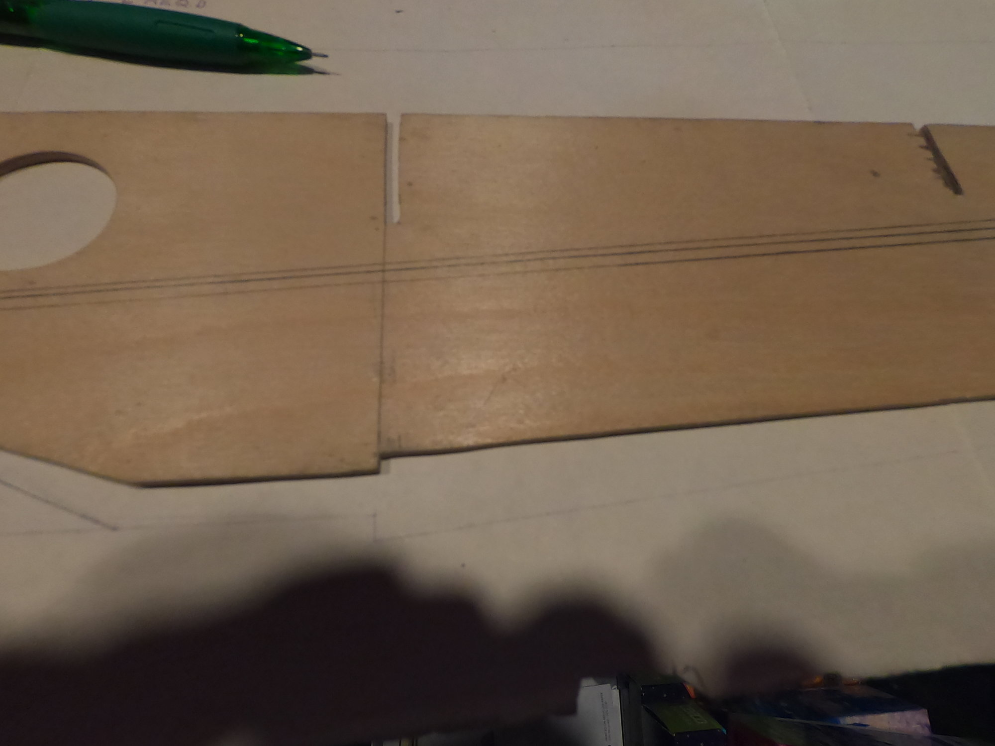
Anyhow, I have the lengthwise frame cut out and took some shots to show the changes I've made. This first shot shows how much I removed from the sponson inside bottom. The straight line at the bottom of the picture is how the plan was drawn. Since this didn't match the full sized boat, I redrew it as can be seen below the cut out part. Something else that is very visible is the areas where I removed plywood from the middle of the part. This was done for two reasons. The first being to reduce the weight of the boat. With the sponson insides, much of the wood is inside the boat and not subject to being exposed to the water and, therefore, it's not really needed. The second reason is that if water does somehow get inside the boat, having sealed areas will trap water inside, making the boat heavier and eventually rotting the wood so this is a way to get water out.
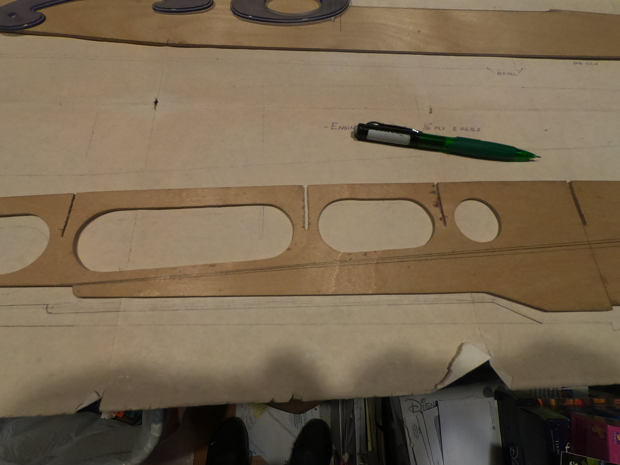 The second picture shows how I notched the bottom of the sponson. This was done to align the bottom of the sponson to the bottom of the airtrap. The inner part of the sponson bottom is angled at 45 degrees, giving the 1/16th(1.5875mm) ply a thickness of 3/32" (2.38mm). How this all works will be shown later in the build
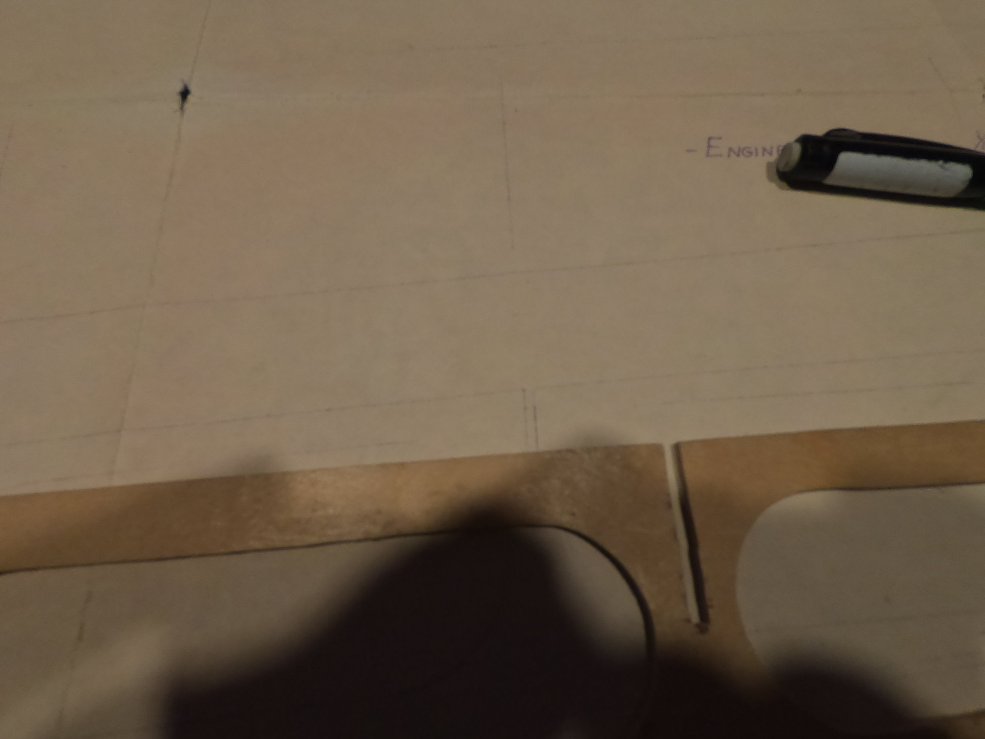
This shot shows the top of the engine bay wall. The cut away area is where the flash pan will be, something not shown anywhere except on the color sheet. For those not familiar with piston powered hydroplanes, it was not uncommon for an exhaust header to fail. When that happened, hot exhaust and still burning fuel would be sent at the deck of the boats and, since the boats were made out of wood, this would tend to set the boat on fire. Metal flash pans were used to prevent the exhaust from hitting the wooden structure.
This last shot shows the slot for the firewall and where the plan shows it to go. When Roger drew up the plan for the Cotts Beverage, the engine bay was covered. With the Pak, it normally ran without an engine cover so, to get the location of the firewall and the front of the cockpit correct, that frame had to be moved forward
Anyhow, I have the lengthwise frame cut out and took some shots to show the changes I've made. This first shot shows how much I removed from the sponson inside bottom. The straight line at the bottom of the picture is how the plan was drawn. Since this didn't match the full sized boat, I redrew it as can be seen below the cut out part. Something else that is very visible is the areas where I removed plywood from the middle of the part. This was done for two reasons. The first being to reduce the weight of the boat. With the sponson insides, much of the wood is inside the boat and not subject to being exposed to the water and, therefore, it's not really needed. The second reason is that if water does somehow get inside the boat, having sealed areas will trap water inside, making the boat heavier and eventually rotting the wood so this is a way to get water out.
The second picture shows how I notched the bottom of the sponson. This was done to align the bottom of the sponson to the bottom of the airtrap. The inner part of the sponson bottom is angled at 45 degrees, giving the 1/16th(1.5875mm) ply a thickness of 3/32" (2.38mm). How this all works will be shown later in the buildThis shot shows the top of the engine bay wall. The cut away area is where the flash pan will be, something not shown anywhere except on the color sheet. For those not familiar with piston powered hydroplanes, it was not uncommon for an exhaust header to fail. When that happened, hot exhaust and still burning fuel would be sent at the deck of the boats and, since the boats were made out of wood, this would tend to set the boat on fire. Metal flash pans were used to prevent the exhaust from hitting the wooden structure.
This last shot shows the slot for the firewall and where the plan shows it to go. When Roger drew up the plan for the Cotts Beverage, the engine bay was covered. With the Pak, it normally ran without an engine cover so, to get the location of the firewall and the front of the cockpit correct, that frame had to be moved forward
Last edited by Hydro Junkie; 05-31-2021 at 12:00 AM.
06-04-2021 | 12:01 PM
#3
Thread Starter
Now that I have a bit of time to work on the boat again, it's time for a quick update. I've (barely)had a chance to epoxy on the bottom stringers on two of the lengthwise frames, a major achievement considering how crazy it's been at work(been called in several times over the past couple of weeks). Now is where things get fun. I know that bass, spruce and fir are fairly soft woods that can be damaged easily. Due to how I'm planning to build the sponsons, I decided it might be better to go with harder wood. Since the boat is being built using birch plywood, I felt the obvious choice would be to use birch for the bulnoses and blocking in the front of the sponsons where it will be exposed. What I failed to anticipate is that birch isn't readably available so it's taken me two days to find some without having to order on line. I know some are going to say "Why use birch?" The most easily to understand answer is that birch is twice as hard as the readily available firs. Using the Janka Hardness Scale, the typical fir has a rating of 660, that being the softest of the normally used domestic woods. Yellow birch, on the other hand, has a rating of 1260. Now, for those like me that have never heard of the Janka Scale, it's a measurement of the force(in pounds in the US) needed to embed a .444"(11.277mm) ball half way into the wood. Getting back to the finding the birch, I ended up finding only one place that carried any birch(other than plywood) and they only sell it in 2ft(61cm) lengths. Needless to say, I figure it's better to have too much with costs skyrocketing, so I bit the bullet and bought a 4ft(122cm) piece, spending $20 in the process. At this point, I think I have all the wood I'll need to build the boat so it's time to start making sawdust
Last edited by Hydro Junkie; 06-04-2021 at 12:04 PM.
06-06-2021 | 07:30 PM
#4
Thread Starter
Not much got done over the past two days due to other things happening. Today, it was an R/C Unlimiteds boat race that I went to part of, as a spectator. My race boat has had a couple of issues that I've been trying to get worked out, just didn't make it for today. Between rain showers and before running a few errands, I got to see four different classes of hydroplanes race:
Getting back to the boats, I should have the rest of the stringers added to the lengthwise frames tonight and will follow that up with getting the three transoms laid out. I'll be doing things slightly different than what the plans show with these parts. To keep the weight down and strength up, I'll be making these frames out of two pieces of plywood, laminated together. The plans show all three parts being cut from 1/4"(6mm) plywood and, in previous builds, that is what I would have done. This time, all three parts will have a 1/16"(1.5mm) outer skin with 3/16(4.5mm) inner framing on the right sponson and rear transom while the left sponson transom will be framed with a second piece of 1/16"(1.5mm) plywood for a total thickness of 1/8"(3mm). I'm sure this will have people wondering "WHY?" The answer is weight. This inner frame will have a lot of the material removed where it's not needed so I'll be cutting lightening holes in the inner frames. As far as using thinner material on the left side, I won't need as much strength since the turn fin will be on the rear of the right sponson. Once I get the three transom part sets cut out, I'll weigh them and then weigh them again after the excess material is removed and they are laminated together. I'll try to keep a running total of how much the boat weighs and how much I've removed as I go along through the build.
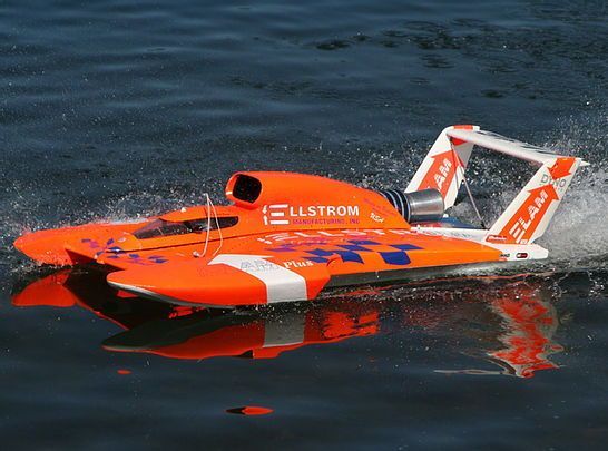
As for my present racer, here's a shot of it running at slow speed:
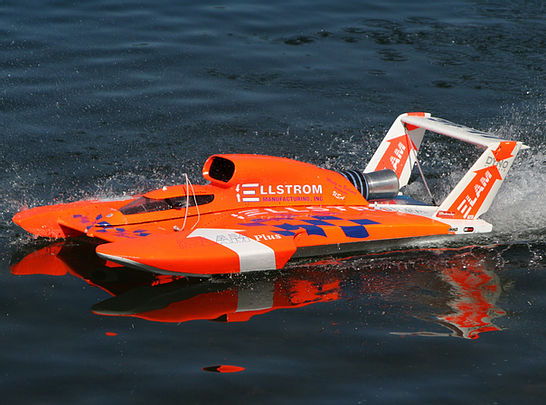
As can be seen in this picture, there isn't a turn fin on the back of the sponson, hence the lighter construction of the sponson transom while the recent picture of the Pak being lowered into the Columbia River shows the turn fin, drive gear and rudder.

- 1:10th scale electric
- 1:8th scale electric
- 1:8th scale nitro
- 1:6.7 scale gas
Getting back to the boats, I should have the rest of the stringers added to the lengthwise frames tonight and will follow that up with getting the three transoms laid out. I'll be doing things slightly different than what the plans show with these parts. To keep the weight down and strength up, I'll be making these frames out of two pieces of plywood, laminated together. The plans show all three parts being cut from 1/4"(6mm) plywood and, in previous builds, that is what I would have done. This time, all three parts will have a 1/16"(1.5mm) outer skin with 3/16(4.5mm) inner framing on the right sponson and rear transom while the left sponson transom will be framed with a second piece of 1/16"(1.5mm) plywood for a total thickness of 1/8"(3mm). I'm sure this will have people wondering "WHY?" The answer is weight. This inner frame will have a lot of the material removed where it's not needed so I'll be cutting lightening holes in the inner frames. As far as using thinner material on the left side, I won't need as much strength since the turn fin will be on the rear of the right sponson. Once I get the three transom part sets cut out, I'll weigh them and then weigh them again after the excess material is removed and they are laminated together. I'll try to keep a running total of how much the boat weighs and how much I've removed as I go along through the build.
As for my present racer, here's a shot of it running at slow speed:
As can be seen in this picture, there isn't a turn fin on the back of the sponson, hence the lighter construction of the sponson transom while the recent picture of the Pak being lowered into the Columbia River shows the turn fin, drive gear and rudder.
Last edited by Hydro Junkie; 06-06-2021 at 09:29 PM.
06-06-2021 | 09:15 PM
#5
Thread Starter
Just got to thinking. I have one sponson inside and one engine bay wall ready to go. Assuming both sides come out about the same, I can take the weights off of the first two and double them for the time being and, if they aren't that close, update the weight later. What I measured the engine bay sidewall at is 4.85 ounces or 136 grams. The sponson inside weighs 5.3 ounces or 150 grams. That gives me a total of 10.15 ounces or 286 grams so, when I double it, I get 20.3 ounces or 572 grams. To keep this simple, I'm going to set up an Excel spread sheet so that I can keep track of the weight of wood, epoxy and hardware as I go. Should be interesting to see how it all breaks down when the build is complete. Since my goal is to be under 12 lbs (5.45Kg), it should be fun to see how close I get. One thing I do need to be very aware of is the back half of the boat has a lot of what can be called "dead weight" This includes the cockpit with all it's details and driver, tails and wing structures, all but the driver being visible in the picture in the previous post. To run properly, the boat needs to balance 1-2 inches(2.54-5.08cm) behind the sponsons so the weight at the back must be kept to a minimum or extra ballast will be needed up front to balance the boat
Last edited by Hydro Junkie; 06-06-2021 at 09:28 PM.
06-14-2021 | 05:08 AM
#6
Thread Starter
I have finally had a chance to get the other two lengthwise frame bottom stringers installed. With that done, the boat weight is 20.3 ounces or 576 grams. My next task will be to get the three transoms made. HOPEFULLY, that will be within a couple of days as this first step has taken way to long due to work and the wife's "Honey Do" list 
07-08-2021 | 05:20 AM
#7
Thread Starter
Sorry for the long delay. I started working on the sponson transoms only to find the plans are so faded(the sheets are well over 15 year old) that I couldn't trace or photo copy them. I tried to darken them with a soft pencil only to find the paper was not up to it so I ordered another set of plan sheets, should be getting them in the next few days. If that is actually the case, I will be able to redraw everything "hopefully" starting next week. I have already picked up a 15 foot long roll of the appropriate width drafting velum so I'll be using new stock to draw everything out on. Stay tuned
UPDATE:
Walked into the house, after work, and found the plans had arrived. Looks like I get to go back to work a bit sooner than expected
UPDATE:
Walked into the house, after work, and found the plans had arrived. Looks like I get to go back to work a bit sooner than expected
Last edited by Hydro Junkie; 07-08-2021 at 08:39 PM.
07-24-2021 | 08:35 PM
#8
Thread Starter
How's that saying go, best laid plans.....
Work has, once again, been a major obstacle to doing anything on the boats. That being said, the wife and I have decided we both need a break so we are taking a week off for a "staycation". What really surprised me is when she told me today "I expect to see some serious work done on the boats since you're not going to work". Guess that means I need to plan on making some progress over the next week. Hopefully, she sticks to that and I'll be able to show some progress in the next couple of days. Needless to say, I'm keeping my fingers crossed")
Work has, once again, been a major obstacle to doing anything on the boats. That being said, the wife and I have decided we both need a break so we are taking a week off for a "staycation". What really surprised me is when she told me today "I expect to see some serious work done on the boats since you're not going to work". Guess that means I need to plan on making some progress over the next week. Hopefully, she sticks to that and I'll be able to show some progress in the next couple of days. Needless to say, I'm keeping my fingers crossed
08-04-2021 | 08:40 PM
#9
Thread Starter
Spent most of the week working on figuring out the bottom of the sponsons, not an easy task due to lack of photos to compare to. Took care of that yesterday with a run down to the HARM, before work, where I was able to get some nice clean shots of the top of the boat, the bottom and transom of the left sponson and the rear transom. I was thinking I had gotten something wrong but, after seeing the boat, I found I wasn't as far off as I thought.
I also got some pictures of some of the other boats. I'll post a few of them as soon as I can download them into my laptop from my Go Pro. Included in the pictures are several Gold Cup winning boats. These include the Miss Bardahl(at least I think it's the right one, there were two almost identical hulls AFAIK), 1970 Budweiser, 1971 Miss Madison, 1973 Pay'N Pak(won twice) 1977 Atlas Van Lines(won multiple times)1980 Miss Budweiser(won twice), 1982 Atlas Van Lines(won twice)
I also got some pictures of some of the other boats. I'll post a few of them as soon as I can download them into my laptop from my Go Pro. Included in the pictures are several Gold Cup winning boats. These include the Miss Bardahl(at least I think it's the right one, there were two almost identical hulls AFAIK), 1970 Budweiser, 1971 Miss Madison, 1973 Pay'N Pak(won twice) 1977 Atlas Van Lines(won multiple times)1980 Miss Budweiser(won twice), 1982 Atlas Van Lines(won twice)
12-31-2021 | 09:16 PM
#10
Thread Starter
I FINALLY have had the chance to look at the boats. I know I said I'd post a few pictures and, as of today, I've gotten a few that I can post that relate to this build.
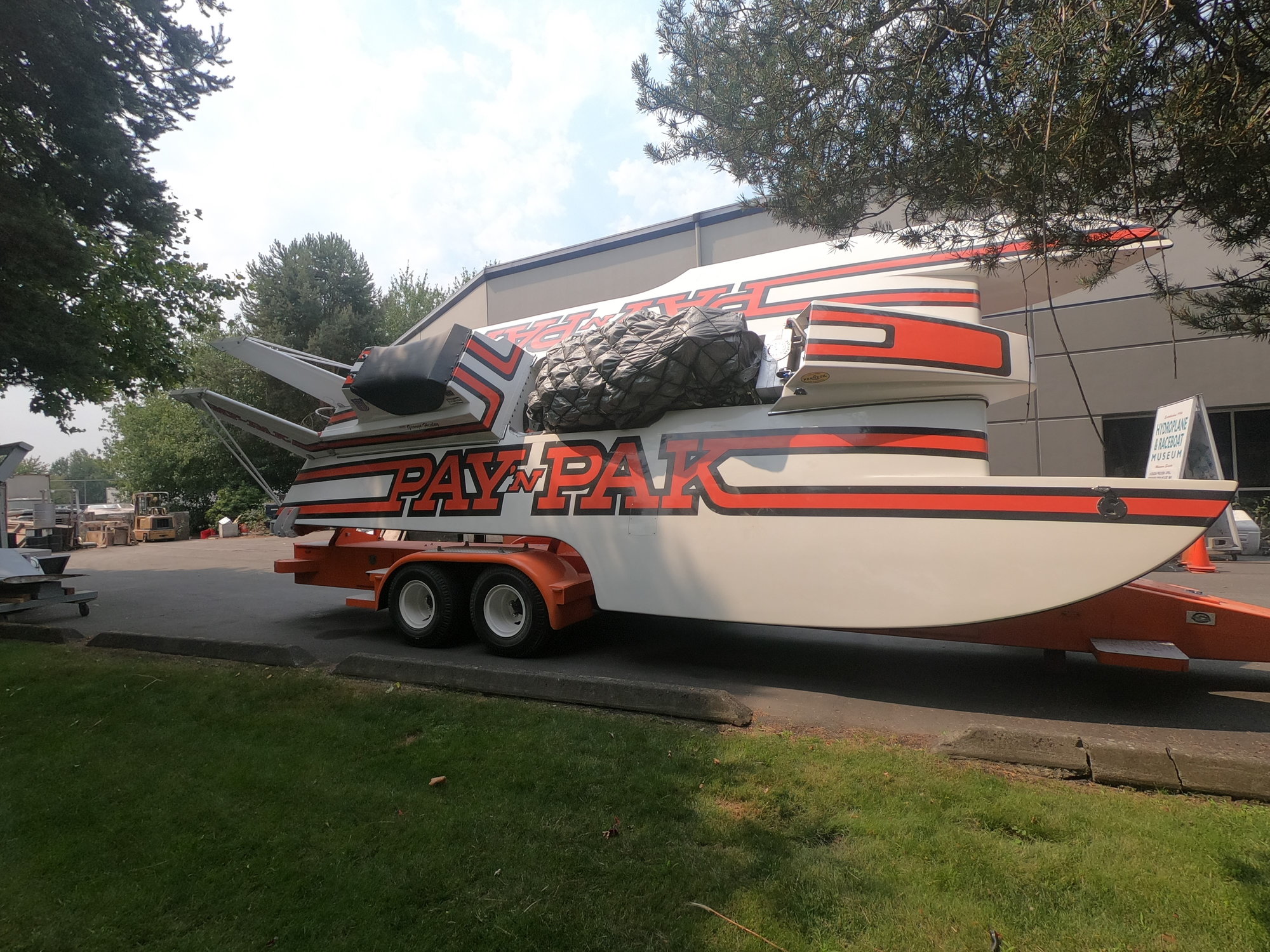
To start with, I figured it would be nice to get a shot of the Pak, sitting on its trailer. Sorry about the engine and cockpit being covered, that was apparently due to the boat being readied to go on a road trip. One thing of interest is the different shade of orange the trailer was painted. The trailer actually has the correct orange for the boat. The painter didn't like it, compared to the black, so he darkened it slightly when painting the stripes and lettering
This shot shows the running surface and sponson transom of the left sponson. The right sponson was a mirror image of this one, other than the metal brackets used to secure the turn fin, when the boat was originally built back in 1972. When the right sponson was pretty much destroyed in 1981, it was replaced with a molded fiberglass sponson that is still on the boat today. What isn't well known is that the fiberglass sponson is actually 3" wider than the built up one shown above.

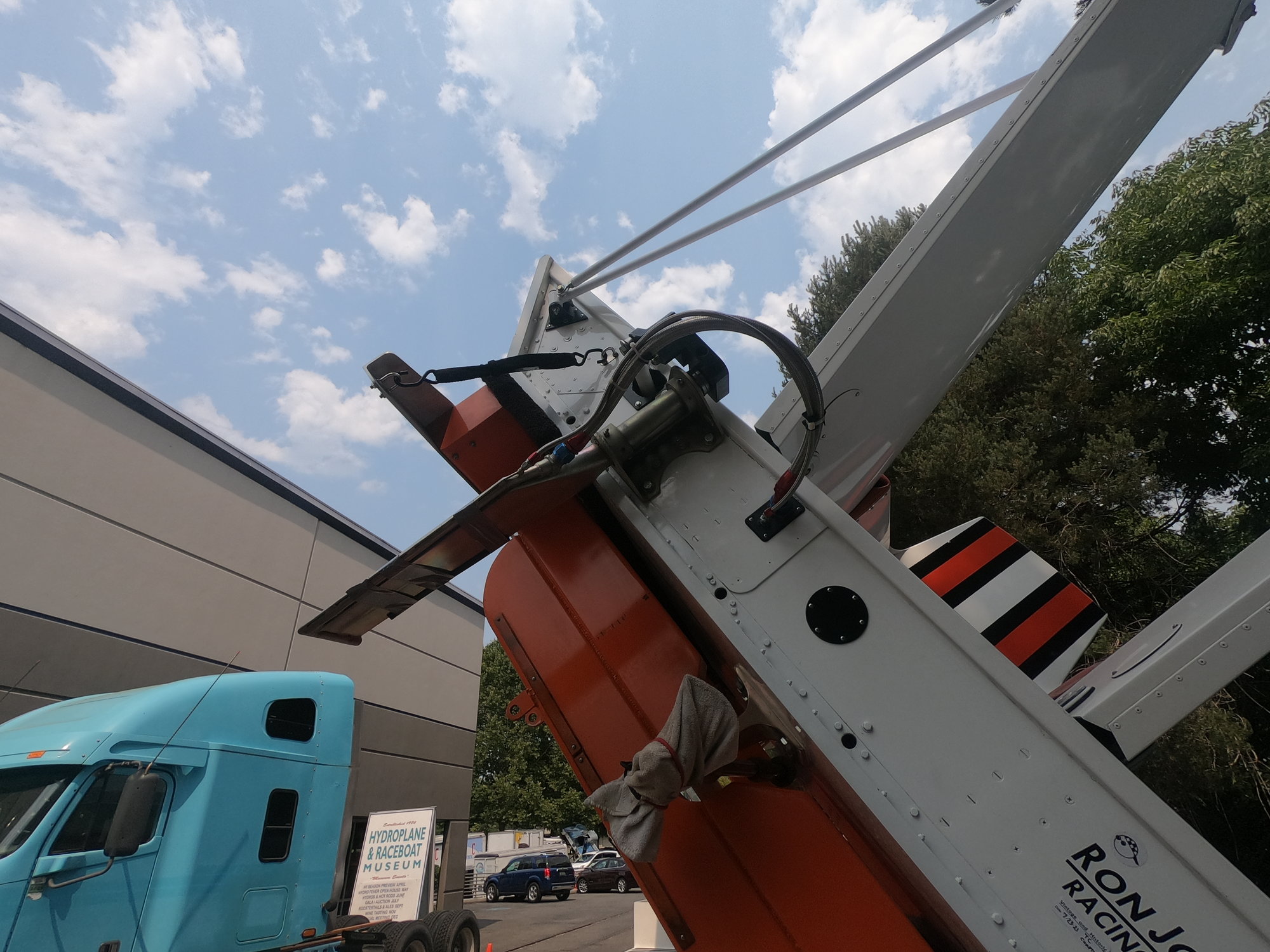
This picture shows the transom of the boat. Four things can be seen in this shot:
1) The vertical tails are directly above the engine bay walls as can be seen by the location of the screws through the transom directly below the tails. These screws show the locations of the brackets securing the engine bay walls to the transom.
2) The tail braces are secured to fittings on the transom, not to fittings on the deck as some believe. The top of the braces are connected to the wing's mounts at the top of the tails, visible in the first shot.
3) The rudder is mounted outside of the left engine bay wall. This is due to where the linkage is installed under the deck. The pushrod, visible to the left of the rudder, is connected to a large sprocket under the deck that is, in turn, wrapped with a heavy bicycle style chain that is connected to the steering cables from the cockpit.
4) Most model builders believe the bottom and sides of the boat are flush with the transom. On many boats, however, the aluminum honeycomb extends past the transom, as shown here. In the case of the Pak, the 1" thick honeycomb extends past the transom by an inch, preventing the water from pulling the boat down when it's travelling at slow speeds heading out from and back to the dock
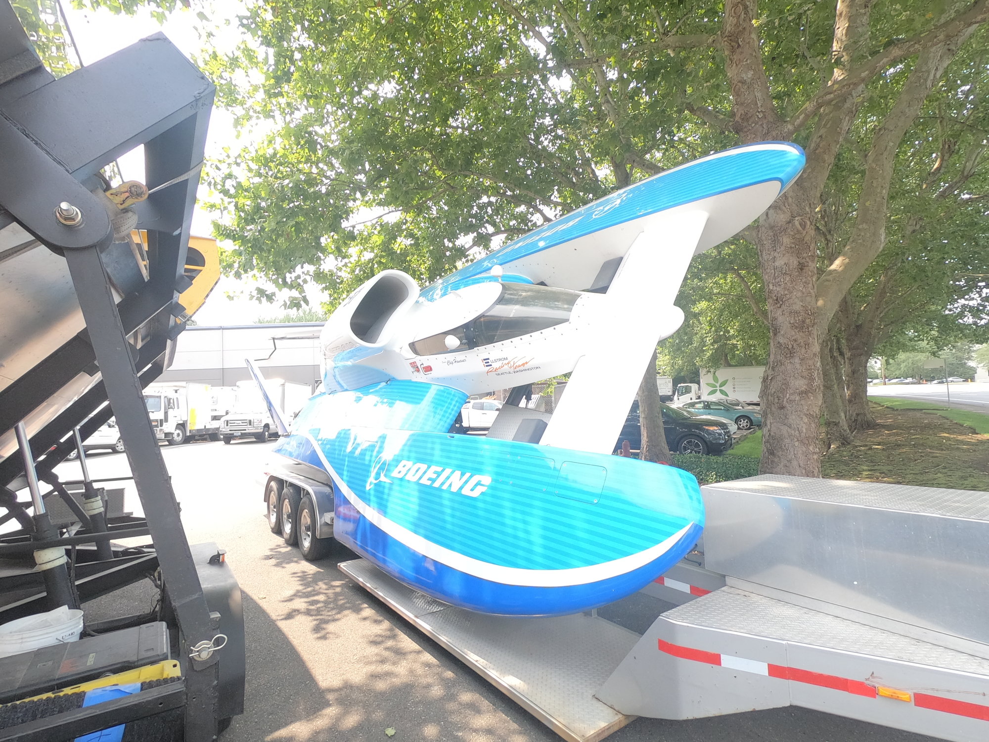
One last shot, this time of the boat I posted a picture of earlier. Six posts back, I posted a picture of my 2000 Elam Plus. This last picture is of the full-sized boat sporting the last paint job it ran with in 2007, a variation of the paint scheme used on the flight test versions of the 787 Dreamliner. It ran a demo heat with a replica of Bill Boeing's Miss Wahoo, powered by an experimental biofuel. It had earlier qualified for the event with the fastest average speed of any competition boat. This wasn't a real surprise to many as the driver for the qualification laps and demo run was "Chip" Hanauer. AFAIK, "Chip" was the last one to drive the boat, which itself hadn't been on the water, other than during biofuel tests, since the end of the 2000 season where Mark Evans drove it to a victory on the Columbia River at the race in Tri-Cities
To start with, I figured it would be nice to get a shot of the Pak, sitting on its trailer. Sorry about the engine and cockpit being covered, that was apparently due to the boat being readied to go on a road trip. One thing of interest is the different shade of orange the trailer was painted. The trailer actually has the correct orange for the boat. The painter didn't like it, compared to the black, so he darkened it slightly when painting the stripes and lettering
This shot shows the running surface and sponson transom of the left sponson. The right sponson was a mirror image of this one, other than the metal brackets used to secure the turn fin, when the boat was originally built back in 1972. When the right sponson was pretty much destroyed in 1981, it was replaced with a molded fiberglass sponson that is still on the boat today. What isn't well known is that the fiberglass sponson is actually 3" wider than the built up one shown above.
This picture shows the transom of the boat. Four things can be seen in this shot:
1) The vertical tails are directly above the engine bay walls as can be seen by the location of the screws through the transom directly below the tails. These screws show the locations of the brackets securing the engine bay walls to the transom.
2) The tail braces are secured to fittings on the transom, not to fittings on the deck as some believe. The top of the braces are connected to the wing's mounts at the top of the tails, visible in the first shot.
3) The rudder is mounted outside of the left engine bay wall. This is due to where the linkage is installed under the deck. The pushrod, visible to the left of the rudder, is connected to a large sprocket under the deck that is, in turn, wrapped with a heavy bicycle style chain that is connected to the steering cables from the cockpit.
4) Most model builders believe the bottom and sides of the boat are flush with the transom. On many boats, however, the aluminum honeycomb extends past the transom, as shown here. In the case of the Pak, the 1" thick honeycomb extends past the transom by an inch, preventing the water from pulling the boat down when it's travelling at slow speeds heading out from and back to the dock
One last shot, this time of the boat I posted a picture of earlier. Six posts back, I posted a picture of my 2000 Elam Plus. This last picture is of the full-sized boat sporting the last paint job it ran with in 2007, a variation of the paint scheme used on the flight test versions of the 787 Dreamliner. It ran a demo heat with a replica of Bill Boeing's Miss Wahoo, powered by an experimental biofuel. It had earlier qualified for the event with the fastest average speed of any competition boat. This wasn't a real surprise to many as the driver for the qualification laps and demo run was "Chip" Hanauer. AFAIK, "Chip" was the last one to drive the boat, which itself hadn't been on the water, other than during biofuel tests, since the end of the 2000 season where Mark Evans drove it to a victory on the Columbia River at the race in Tri-Cities
Last edited by Hydro Junkie; 12-31-2021 at 09:26 PM.
01-01-2022 | 09:47 PM
#11
Thread Starter
Needless to say, having a picture helped. My "guestimates" were way off. I found that, between previously taken measurements and the picture posted yesterday, the runner is much "flatter" than I thought. I know the actual sponson bottoms are set at 3 degrees but what I missed, and would have missed without the picture, is that there is a .75" difference in depth of the edges of the runners below the sponson bottom. The outer edge is further from the bottom than the inside edge. Since the rear of the runner is 14" wide, this would mean the runner is only at 1-2 degrees and not the 3 degrees I thought it was. Now I get to start over on drawing the runners, if I want them to be close to accurate. Can we say "FRUSTRATING!!!!!!!!"
01-04-2022 | 05:24 PM
#12
Thread Starter
And, once again, I got fooled. I redrew the left sponson bottom and found the runner had no dihedral at all, it's totally flat from side to side. That means I don't have to redraw the right sponson at all, it's already done
Now I get to start working on the forward cross frame the bulnose block, which will be made out of birch,will be epoxied to. This one should really be fun since I have to draw the whole thing from scratch
Now I get to start working on the forward cross frame the bulnose block, which will be made out of birch,will be epoxied to. This one should really be fun since I have to draw the whole thing from scratch
Last edited by Hydro Junkie; 01-04-2022 at 05:29 PM.
02-12-2022 | 05:53 PM
#13
Thread Starter
Finally, things at work have slowed down a bit, that is if you call multiple double(17hour) shifts slowing down. I've gotten most of the forward cross frame drawing done, just have to figure out the runner depth and angle. All of the extra hours at work did let me order a new toy that should speed up the build a little. This arrived today: 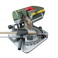
Should make the miter cuts I've always had to do with a Exacto saw and miter box a lot faster and more accurate. Hopefully, I'll get to try it out tomorrow, along with a table saw I haven't used yet
Should make the miter cuts I've always had to do with a Exacto saw and miter box a lot faster and more accurate. Hopefully, I'll get to try it out tomorrow, along with a table saw I haven't used yet
05-01-2022 | 04:32 PM
#14
Thread Starter
And, again, work has kept me away from the boats. I did manage to get the forward frame drawn out, just need to get it transferred to the plywood and cut out. Unfortunately, the "honey do" list got me for most of the weekend so, hopefully, I'll be able to get that done this evening and get some pictures posted in the next day or two.
05-28-2022 | 02:22 PM
#16
Thread Starter
FINALLY, A WEEKEND THAT'S DEDICATED TO BUILDING BOATS!!!!!
I actually have three days where I'm not wiped out from or having to worry about work where I can get something done on the boats. That said, I found, earlier today, that I need to get the sponson sheers cut out so that I can get the outer edges of the sponson frames properly sized. Fortunately, I have a copier/printer so that made quick work of making templates for those parts. Hopefully, I'll have pictures to post on some actual progress before the weekend's over.
I actually have three days where I'm not wiped out from or having to worry about work where I can get something done on the boats. That said, I found, earlier today, that I need to get the sponson sheers cut out so that I can get the outer edges of the sponson frames properly sized. Fortunately, I have a copier/printer so that made quick work of making templates for those parts. Hopefully, I'll have pictures to post on some actual progress before the weekend's over.
05-31-2022 | 04:05 PM
#17
Thread Starter
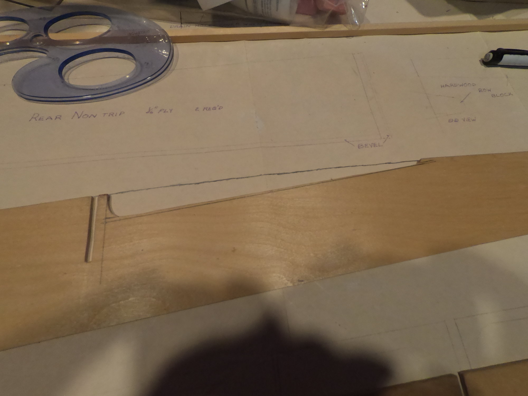
After getting my building time interrupted, it's back to work. Here's the first shot I was able to take of the sponson sheer pattern laid out
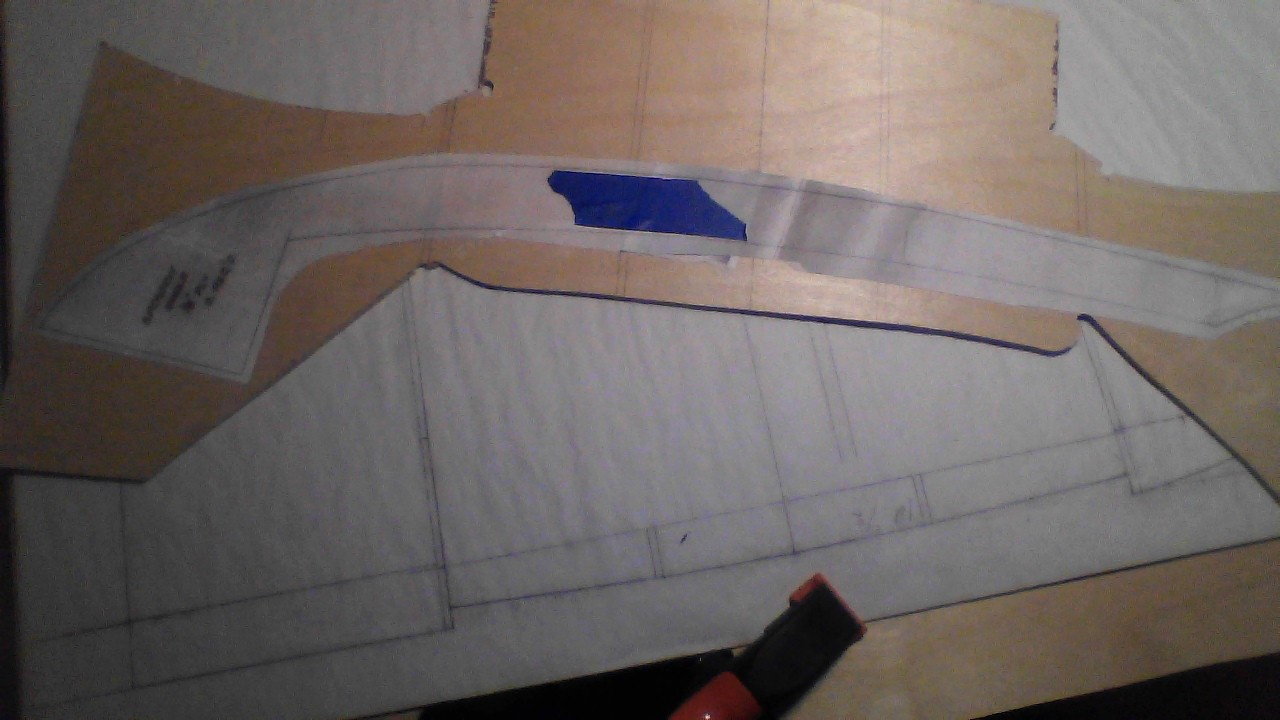
As you can see, it was glued to a piece of scrap 1/8" ply and is ready to be completed. Below the ply is a rough drawing of the forward most bulkhead. Before I can finish that drawing, I need to get the sheers made so I can fit the bulkhead properly.
As you can see, it was glued to a piece of scrap 1/8" ply and is ready to be completed. Below the ply is a rough drawing of the forward most bulkhead. Before I can finish that drawing, I need to get the sheers made so I can fit the bulkhead properly.
09-10-2022 | 10:06 PM
#18
Thread Starter
And, once again, work and other things have kept me away from the boats.
Tomorrow was supposed to be a race day but, due to my work schedule, I've decided to pass on the race and sleep in so I can be "somewhat awake" to go to work on the overnight shift. Instead of racing, I'll be spending my prework time working on the Pak. I have made a decision that will make the right sponson transom a bit harder to do. I've decided to make the transom a "sandwich" by using 1/16" aluminum to face it with on the outside, a 3/16" thick plywood center and a 3/16" thick inside aluminum plate with the two inner pieces lightened with lightening holes to keep the weight down as much as possible. I'm still trying to decide if I should screw the inner aluminum plate to the plywood core or just epoxy them together. I guess I'll have to see how well the glue holds the two together and go from there
Tomorrow was supposed to be a race day but, due to my work schedule, I've decided to pass on the race and sleep in so I can be "somewhat awake" to go to work on the overnight shift. Instead of racing, I'll be spending my prework time working on the Pak. I have made a decision that will make the right sponson transom a bit harder to do. I've decided to make the transom a "sandwich" by using 1/16" aluminum to face it with on the outside, a 3/16" thick plywood center and a 3/16" thick inside aluminum plate with the two inner pieces lightened with lightening holes to keep the weight down as much as possible. I'm still trying to decide if I should screw the inner aluminum plate to the plywood core or just epoxy them together. I guess I'll have to see how well the glue holds the two together and go from there
12-02-2022 | 06:18 AM
#19
Thread Starter
It's been almost three months since my last post and, as per usual, life has gotten in the way. Work has been the major culprit but the boat hasn't helped. Over the past several months, I've repeatedly reworked the bottom of the sponson transom, to no avail. For some reason, the numbers just didn't work. As frustration started to set in, I went back and looked at the following picture again:
Then it hit me:
I had been laying everything out with the vertical lines parallel to the sponson inside!!!!!
What if the ride pad supports were at 90 degrees to the actual sponson bottom? If that is the case, and the picture above seems to suggest that it is, could it be enough to throw off my work? Since I'm working today in South Seattle, it's only a few miles to the HARM so I'm going to head down after work and see if that's where the problem lies.
12-03-2022 | 06:52 PM
#20
Thread Starter
A day later than I had planned, I got down to the HARM. What I found is that the ride pad structure is indeed installed at 90 degrees to the actual bottom of the sponsons. With that said, I found something else that I hadn't taken into account. I rechecked the angle of the inner edge bevel and made a shocking discovery. I had assumed that the bevel was at 45 degrees for it's whole length. What I found today is that it's actually at 50 degrees at the sponson transom and 54 degrees at the forward most internal frame location of the model's sponson. That pretty much tells me why I couldn't get anything to line up properly when I was trying to redraw the sponson frames. At least, at this point, I don't have to start from scratch
12-04-2022 | 12:43 PM
#22
Thread Starter
Which part? Since I'm redesigning the boat, pretty much from the ground up due to inaccurate plans, the entire project is basically a draw/ check the fit/ revise process.
While I was at the HARM, I was talking to a guy working on the restoration of the Nitrogen II, known by many as the Miss Madison. This particular boat became famous when it won the 1971 APBA Gold Cup where it had to defeat many newer boats that were superior in both design and capability. Getting back to the conversation, I had commented on how good the woodworking looked in the boat's restoration. He surprised me when he told me his task was easier than mine since he was working the original framing so all he had to do was make all of the new parts fit. Next time I go down, I'll take a camera so I can take some pictures of the beautiful work being done on this historic boat
While I was at the HARM, I was talking to a guy working on the restoration of the Nitrogen II, known by many as the Miss Madison. This particular boat became famous when it won the 1971 APBA Gold Cup where it had to defeat many newer boats that were superior in both design and capability. Getting back to the conversation, I had commented on how good the woodworking looked in the boat's restoration. He surprised me when he told me his task was easier than mine since he was working the original framing so all he had to do was make all of the new parts fit. Next time I go down, I'll take a camera so I can take some pictures of the beautiful work being done on this historic boat
11-20-2023 | 06:05 PM
#23
Thread Starter
WOW!!!! Hard to believe it's been almost a year since my last post in this thread.
Between health issues, work and other commitments, I haven't had a chance to do anything on the boats. I'll finally be getting a chance, starting Wednesday, to really get something done on them. I Learned, earlier today, that a cashier's check that I mailed over a month ago to my fiberglass parts supplier finally arrived today. This means I'll be getting my parts, for two other builds, most likely in early to mid January. I'm getting a 5 day weekend, with nothing on the schedule(that I know of anyway), so I should be able to actually get some building done on the Pak over that time. I did, however, get to attach some copies of a few frames onto some plywood and (very)rough cut the parts out. A bit of sanding and adding some birch hardwood blocks and I can start epoxying some parts together
Between health issues, work and other commitments, I haven't had a chance to do anything on the boats. I'll finally be getting a chance, starting Wednesday, to really get something done on them. I Learned, earlier today, that a cashier's check that I mailed over a month ago to my fiberglass parts supplier finally arrived today. This means I'll be getting my parts, for two other builds, most likely in early to mid January. I'm getting a 5 day weekend, with nothing on the schedule(that I know of anyway), so I should be able to actually get some building done on the Pak over that time. I did, however, get to attach some copies of a few frames onto some plywood and (very)rough cut the parts out. A bit of sanding and adding some birch hardwood blocks and I can start epoxying some parts together
Last edited by Hydro Junkie; 11-20-2023 at 06:35 PM.
01-09-2024 | 01:06 AM
#24
Thread Starter
And, once again, I get held up by other things. Ended up in the hospital over Christmas and am now on very limited activity. I did find a box sitting on my front porch with fiberglass boat parts when I got home so the holidays weren't a total loss. Now, just have to wait for my medical staff to give me the okay to start working on projects again
10-14-2024 | 09:08 PM
#25
Thread Starter
And here I am, almost 10 months after getting out of the hospital. At this point, I'm not sure who's worse, the doctors or the wife. They all keep reminding me that I'm still healing up so I've been very limited on doing much beyond going to work(on limited duty no less) or sitting around the house. Needless to say, it's been driving me crazy
With that all said, I've had major change at work. Due to a labor dispute, I've been going to work in a ghost town. That's given me the chance to start working on boats at work, at least for now. While I still have my Pak to work on, it's not far enough along to bring to work. Due to that, I started bringing a partially framed up hull for a new 2000 Elam Plus(to replace the one pictured below) to work. The plan to try and get both it and the Pak done in time for the 2025 season.
I have all the FG parts needed, those having been the box sitting on my front porch back in December when I got home from my hospital stay so I won't have to wait for them to arrive. Today's tasks are to cut the glue blocks that will be used to fasten the nontrips(the rear side panels) to the framing. Having a mini power miter box and hobby sized belt/disc sander definitely makes the task quicker. If I don't have any fitting issues, I'll(hopefully) get everything glued down tomorrow. I'll try to post a couple of pictures in a few days so I'll be able to at least show some progress.

