


Phoenix Models 1/4 scale Lysander


 05-07-2017 | 10:48 PM
#4


My Feedback: (2)
Joined: Mar 2003
Posts: 244
Likes: 0
Received 0 Likes
on
0 Posts
From: Ferndale, MI
Mine has shipped, supposed to arrive Tuesday the 9th. Have a G-62 ready for trial fitment, may have to put some components toward the rear to balance. We will see. I could go electric if the weight and balance would be better.
By the way, the first shipment has sold out. Next is listed as late June.
Oh this is interesting: Zenoah G-62 magneto version = 82oz, plus 24oz fuel = 102oz
And........................: 2 x 6s 5000mAh Lipo + Rimfire 50cc motor = 102oz
Same weight, engine will be more nose heavy. Like I said, we'll see which balances better.
Last edited by Wile E; 05-08-2017 at 12:01 AM.
05-10-2017 | 07:14 PM
#5
OK, it showed up.
It was an adventure getting this into my basement, as it was too long so I had to stand it on end to make it around the corner through the top door. This cause several alarming thuds to issue from inside. Box seemed to be in pretty good condition; a few dings and punctures but nothing serious.
Please excuse the clutter, bad lighting and mediocre photography.
The great unboxing...

The box - this is REALLY big. That's a meter stick on top of it. As you will see, my workshop was unprepared for this, so this will be presented in stages.

The inside. Typical Vietnamese packing job - large pieces wrapped in fairly thick bubble wrap, other parts wrapped in foam wrap, everything loosely packed and stuck together with yards of packing tape.

Under the tailplanes and decal sheet are the wings...

The tail planes

Under the main wings and the main divider we find the fuse, wheel pants and cowl...

The cowl is closed off as a container for most of the smaller parts.

The wing struts were loose in the box, and probably the source of the loudest thuds. These are about a foot and a half long.

Wheel pants, main gear, tail gear and mounting hardware. The top three items were also tumbling around loose in the box.

Bag containing dummy motor and misc cowl mounting hardware.

The fuselage. OK, it would have taken me 15 minutes to clear enough bench space for this, so I just stood it up in the box top.

At the bottom of the box, the instruction manual. Seems pretty detailed...

The contents of the cowl - wheels, spinner, fuel tank, and motor mount.

Coming up - unwrapping.
It was an adventure getting this into my basement, as it was too long so I had to stand it on end to make it around the corner through the top door. This cause several alarming thuds to issue from inside. Box seemed to be in pretty good condition; a few dings and punctures but nothing serious.
Please excuse the clutter, bad lighting and mediocre photography.
The great unboxing...
The box - this is REALLY big. That's a meter stick on top of it. As you will see, my workshop was unprepared for this, so this will be presented in stages.
The inside. Typical Vietnamese packing job - large pieces wrapped in fairly thick bubble wrap, other parts wrapped in foam wrap, everything loosely packed and stuck together with yards of packing tape.
Under the tailplanes and decal sheet are the wings...
The tail planes
Under the main wings and the main divider we find the fuse, wheel pants and cowl...
The cowl is closed off as a container for most of the smaller parts.
The wing struts were loose in the box, and probably the source of the loudest thuds. These are about a foot and a half long.
Wheel pants, main gear, tail gear and mounting hardware. The top three items were also tumbling around loose in the box.
Bag containing dummy motor and misc cowl mounting hardware.
The fuselage. OK, it would have taken me 15 minutes to clear enough bench space for this, so I just stood it up in the box top.
At the bottom of the box, the instruction manual. Seems pretty detailed...
The contents of the cowl - wheels, spinner, fuel tank, and motor mount.
Coming up - unwrapping.
05-11-2017 | 04:13 PM
#7
My Feedback: (2)
Joined: Mar 2003
Posts: 244
Likes: 0
Received 0 Likes
on
0 Posts
From: Ferndale, MI
Drat, you guys beat me to it. I arrived home to find a coffin-size box at my side door, the UPS driver must have had fun getting it up the driveway. Took it in the back door and unboxed in the living room. Lots of bubble wrap and foam sheets. Found some loose bolts which turned out to be for the landing gear, one bolt and some washers missing, so off to the well-stocked hardware store. The shipping carton is shown standing next to a 6 foot fence in the photo, another "cardboard condo". Mods to the firewall begin for mounting the Zenoah G-62. More to come.
05-11-2017 | 11:35 PM
#9
So the unpacking is complete... I gave up on trying to clear enough space to photograph in the shop, so I moved the big parts to the front lawn get get them in a good enough position.
Despite the dings in the box and the loose items, the only damage I found to anything was the cowl ring being cracked (no biggy, as you'll see).
The fuselage appears to be entirely ply, balsa and sheeting, covered with Oracover. they did a really nice job of the covering. No dings or wrinkles are apparent. The cockpit is a removable hatch, that is held on by a spring loaded latch on the top. As has been said, this thing is huge...

The interior is indeed cavernous.

My big hands will fit way back in there with no problems at all.

The surfboards, er, wings are also nicely covered, with no dings or wrinkles. Pull strings are threaded through to the servo hatches.

The wingtip nav lights are crying out for a lighting system. They are faked here by little painted bumps, but both sides are red.

The canopy glass is pretty fuzzy. This isn't all bad as the instrumentation is not even the right colors, let alone accurate, and the pilot figure is a joke. This is the biggest disappointment for me.


The motor mount is substantial, and has a fair amount of right thrust built in it. It doesn't appear to have down thrust built in.


The tail has another hatch with spring loaded retaining latch, to allow easy access to the tail gear mounting and steering hardware. The horizontal stab mounts appear majorly over-engineered to me.


A horizontal stab half, again nicely covered and without wrinkles. All control surfaces are hinged, but not glued.

The wheel pants are very substantial fiberglass parts. I wouldn't even bother to reinforce these. The landing lights again contain red painted bumps for bulbs.


The cowl is monstrous, I believe you might even be able to get a G62 in there without cutting. It is very thick and nicely painted, with a few very minor defects.I want to add the very obvious exhaust to the outside of it that the prototype has, and this will be a challenge to make as nicely as the rest of the cowl.

There is an included two-piece dummy radial, a plywood cowl ring (that cracked in half in transit; because of the way it is mounted to the fuse this really makes no difference).

Here are the very substantial main landing gear legs, which appear to be thickly painted very stiff aluminum. Also in this picture is the mounting hardware, the tail gear (which is sprung), a nice tail wheel, a very sturdy plastic spinner, very nice control horns and mounting hardware, what looks to be about a 20oz fuel tank, and the control rods (which run in pre-mounted tubes in the fuse). Looking at this so far, I won't be replacing any of it.

Also included is an electric motor mount set, including aluminum standoffs, for those of you crazy enough to fly something this size on batteries... Also here are the sturdy aluminum wing tubes and stab tube.

Finally, we have the main wheels. They are about 5", and rather than the cheezy foam we've been seeing on models like this, appear to be foam-filled plastic. They are very hard. If you're finicky, you might want to spend $75 on nice rubber ones, but I won't bother to start with.

So on with the assembly!
Despite the dings in the box and the loose items, the only damage I found to anything was the cowl ring being cracked (no biggy, as you'll see).
The fuselage appears to be entirely ply, balsa and sheeting, covered with Oracover. they did a really nice job of the covering. No dings or wrinkles are apparent. The cockpit is a removable hatch, that is held on by a spring loaded latch on the top. As has been said, this thing is huge...
The interior is indeed cavernous.
My big hands will fit way back in there with no problems at all.
The surfboards, er, wings are also nicely covered, with no dings or wrinkles. Pull strings are threaded through to the servo hatches.
The wingtip nav lights are crying out for a lighting system. They are faked here by little painted bumps, but both sides are red.
The canopy glass is pretty fuzzy. This isn't all bad as the instrumentation is not even the right colors, let alone accurate, and the pilot figure is a joke. This is the biggest disappointment for me.
The motor mount is substantial, and has a fair amount of right thrust built in it. It doesn't appear to have down thrust built in.
The tail has another hatch with spring loaded retaining latch, to allow easy access to the tail gear mounting and steering hardware. The horizontal stab mounts appear majorly over-engineered to me.
A horizontal stab half, again nicely covered and without wrinkles. All control surfaces are hinged, but not glued.
The wheel pants are very substantial fiberglass parts. I wouldn't even bother to reinforce these. The landing lights again contain red painted bumps for bulbs.
The cowl is monstrous, I believe you might even be able to get a G62 in there without cutting. It is very thick and nicely painted, with a few very minor defects.I want to add the very obvious exhaust to the outside of it that the prototype has, and this will be a challenge to make as nicely as the rest of the cowl.
There is an included two-piece dummy radial, a plywood cowl ring (that cracked in half in transit; because of the way it is mounted to the fuse this really makes no difference).
Here are the very substantial main landing gear legs, which appear to be thickly painted very stiff aluminum. Also in this picture is the mounting hardware, the tail gear (which is sprung), a nice tail wheel, a very sturdy plastic spinner, very nice control horns and mounting hardware, what looks to be about a 20oz fuel tank, and the control rods (which run in pre-mounted tubes in the fuse). Looking at this so far, I won't be replacing any of it.
Also included is an electric motor mount set, including aluminum standoffs, for those of you crazy enough to fly something this size on batteries... Also here are the sturdy aluminum wing tubes and stab tube.
Finally, we have the main wheels. They are about 5", and rather than the cheezy foam we've been seeing on models like this, appear to be foam-filled plastic. They are very hard. If you're finicky, you might want to spend $75 on nice rubber ones, but I won't bother to start with.
So on with the assembly!
Last edited by RickVB; 05-12-2017 at 12:06 AM.
05-12-2017 | 01:46 AM
#10
My Feedback: (2)
Joined: Mar 2003
Posts: 244
Likes: 0
Received 0 Likes
on
0 Posts
From: Ferndale, MI
RickVB
I see you are in Novi. I'm in Ferndale, club is Skymasters.
Anyway, purchased some 5 1/2" DuBro inflatable treaded wheels for some cushioning in the landing gear, also went with a 2" aluminum hubbed tail wheel. Sent an order request to Cal-Grafx for some custom numbers per the attached photo so we won't all have the same markings. Fake engine is glued up into the cowling and G-62 fitment trials will begin.
05-12-2017 | 04:38 AM
#11
My Feedback: (2)
Joined: Mar 2003
Posts: 244
Likes: 0
Received 0 Likes
on
0 Posts
From: Ferndale, MI
Firewall pre-drilled bolt holes were filled with dowels. New mounting points for the G-62 were drawn and drilled. A 1/8" aluminum backing plate was constructed for the back side of the firewall to spread the load of the through bolts (all will be thoroughly epoxied and braced on the inside, also). Engine was bolted up to the firewall and the cowling slid into place. TADA! Engine fits inside cowling, may need a bump for the spark plug cap. Specs for a custom Bisson wraparound muffler have been sent for a quote, the mod would raise the assembly to almost level for inside cowl clearance.
 05-12-2017 | 11:14 AM
#13
WileE,
Yes, I believe we've conversed online before regarding the Top Flite P6-E Hawk. (That's not done yet, either .)
.)
How does the cowl look with the engine mounted? Wondering if all that right thrust built in causes it to look cockeyed...
After thinking about it, I might want to change over to balloon tires too, as the gear setup seems very unforgiving and a lot of shock will be transferred to those long, thin wings.
Yes, I believe we've conversed online before regarding the Top Flite P6-E Hawk. (That's not done yet, either
.)How does the cowl look with the engine mounted? Wondering if all that right thrust built in causes it to look cockeyed...
After thinking about it, I might want to change over to balloon tires too, as the gear setup seems very unforgiving and a lot of shock will be transferred to those long, thin wings.
05-12-2017 | 04:10 PM
#14
Got the motor mounted today. I also had to fill holes and re drill. My cowl mounting ring was broken also but like you said, it's no problem. Cowl not mounted yet as the dummy radial is curing. I also don't care for the hard foam wheels bit I have a pair of Du Bro 5" that I think will work fine. I am doing the Canadian Forces plane also and graphics are ordered. Also ordered landing lights and new spinner for 3 blade prop.
05-13-2017 | 06:11 PM
#16
My Feedback: (2)
Joined: Mar 2003
Posts: 244
Likes: 0
Received 0 Likes
on
0 Posts
From: Ferndale, MI
Another Cal-Grafix order for numbers? I just got my quote back for $36.50 for the 416 number set, will be confirming the order. I purchased a TruTurn 3" Cub Style Hub for use with a 3-blade prop. It sits on the prop face and can be used with different props. I have a Mejzlik 3-blade 20 x 10 already, but will look for a XOAR WWII painted version. I may have to add weight to the tail, so am considering elevator servo mounting methods, one per stab.
05-13-2017 | 07:08 PM
#17
My Feedback: (2)
Joined: Mar 2003
Posts: 244
Likes: 0
Received 0 Likes
on
0 Posts
From: Ferndale, MI
Flying the Shuttleworth Collection's LYSANDER: https://haa-uk.aero/document/flying-...w-ii-lysander/
RC LYSANDER stall testing:
(not mine)
DO NOT STALL THIS AIRCRAFT AT LOW ALTITUDE!!
RC LYSANDER stall testing:
DO NOT STALL THIS AIRCRAFT AT LOW ALTITUDE!!
Last edited by Wile E; 05-15-2017 at 05:08 PM. Reason: Brain fart, wrote Lancaster instead of Lysander
05-14-2017 | 02:48 PM
#19
My Feedback: (2)
Joined: Mar 2003
Posts: 244
Likes: 0
Received 0 Likes
on
0 Posts
From: Ferndale, MI
G-62 engine fitment:
Using the Toni Clark cast aluminum 90 degree bend carb adapter: https://www.aeroscale.shop/collectio...um-intake-bend
and 7 mm thermal block : https://www.aeroscale.shop/collectio.../thermal-block as a spacer along with the regular carb block,
and an 18 mm intake tube:https://www.aeroscale.shop/collectio...nt=40161414791 from Vogelsang Aeroscale, plus some fine work with a Dremel tool, the carb lays nicely along the motor box. A choke rod will come out of the cowl ring and be hidden by the cowl flaps. An ignition kill switch will also be hidden in the cowl flap opening.
Last edited by Wile E; 05-14-2017 at 02:53 PM. Reason: Forgot photos
05-16-2017 | 01:57 PM
#22
So I have a much more complicated engine mount story, confounded by my inability to "just put it together" without alterations...
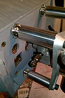
I am using the Saito FG-60R3 radial, and the mount spacing is such that the holes in the firewall will be very close to the edge at the top, even if I were to mount it upright and square (which I don't plan to, as you will see). I just bolted the standoffs to the mount plate to eyeball the position on the firewall, and you can see it's probably tight (note that the fuse is inverted in this photo)...
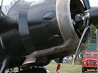
To further complicate matters, I stubbornly wish to add what I consider the most glaringly obvious omission on the model, and that's the external exhaust extension on the outside of the cowl:
I could just make it cosmetic, but where'd be the fun in that...") So I need to route the actual engine exhaust out through the cowl bottom side, so it can exit in the scale position. However (again), I have an exhaust ring that outputs on the bottom, which means I'd have to route it sideways, then back, etc. Which I could do, but where's... well you know.
So I need to route the actual engine exhaust out through the cowl bottom side, so it can exit in the scale position. However (again), I have an exhaust ring that outputs on the bottom, which means I'd have to route it sideways, then back, etc. Which I could do, but where's... well you know.
So it occurred to me that I could rotate the engine 1 scale cylinder (as in 1/9 of the circle or 40*) have have the exhaust in the exact right spot. Problem is, that makes the mount spacing even worse...

You can see if I am to mount it in this manner, I will need a new larger firewall to mount it to. One more wrinkle is that the instructions call for the firewall-to-thrustwasher distance to be 170mm, and I measure stock mount on the engine to the thrust washer as about 180mm already. So just doing something like cutting of the front edges of the motor box and slapping a larger firewall on it won't work unless I significantly shorten the standoffs, which will probably result in other interference problems.
To make things even worse, this motor mount is put together like a Chinese puzzle. The firewall has tabs that stick through the sides and top of the motorbox, and the sides are actually two extended plies that continue through the front former and the next two formers inside the fuse (being joined by a third ply in the process). See the single-headed arrows in the pictures below. Thus, disassembling this mess is out of the question, and some cutting must be done.

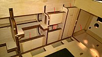
I am thinking of just cutting the whole front off the box, right behind the current firewall, along the double headed arrows above, and in the photo below. Then I think some 3/4 ply might be just the right size, and glued and pinned it might be strong enough. What do you all think?

I am using the Saito FG-60R3 radial, and the mount spacing is such that the holes in the firewall will be very close to the edge at the top, even if I were to mount it upright and square (which I don't plan to, as you will see). I just bolted the standoffs to the mount plate to eyeball the position on the firewall, and you can see it's probably tight (note that the fuse is inverted in this photo)...
To further complicate matters, I stubbornly wish to add what I consider the most glaringly obvious omission on the model, and that's the external exhaust extension on the outside of the cowl:
I could just make it cosmetic, but where'd be the fun in that...
So I need to route the actual engine exhaust out through the cowl bottom side, so it can exit in the scale position. However (again), I have an exhaust ring that outputs on the bottom, which means I'd have to route it sideways, then back, etc. Which I could do, but where's... well you know.So it occurred to me that I could rotate the engine 1 scale cylinder (as in 1/9 of the circle or 40*) have have the exhaust in the exact right spot. Problem is, that makes the mount spacing even worse...
You can see if I am to mount it in this manner, I will need a new larger firewall to mount it to. One more wrinkle is that the instructions call for the firewall-to-thrustwasher distance to be 170mm, and I measure stock mount on the engine to the thrust washer as about 180mm already. So just doing something like cutting of the front edges of the motor box and slapping a larger firewall on it won't work unless I significantly shorten the standoffs, which will probably result in other interference problems.
To make things even worse, this motor mount is put together like a Chinese puzzle. The firewall has tabs that stick through the sides and top of the motorbox, and the sides are actually two extended plies that continue through the front former and the next two formers inside the fuse (being joined by a third ply in the process). See the single-headed arrows in the pictures below. Thus, disassembling this mess is out of the question, and some cutting must be done.
I am thinking of just cutting the whole front off the box, right behind the current firewall, along the double headed arrows above, and in the photo below. Then I think some 3/4 ply might be just the right size, and glued and pinned it might be strong enough. What do you all think?
Last edited by RickVB; 05-17-2017 at 06:52 AM.
05-17-2017 | 10:56 AM
#23
My Feedback: (2)
Joined: Mar 2003
Posts: 244
Likes: 0
Received 0 Likes
on
0 Posts
From: Ferndale, MI
I am thinking of just cutting the whole front off the box, right behind the current firewall, along the double headed arrows above, and in the photo below. Then I think some 3/4 ply might be just the right size, and glued and pinned it might be strong enough. What do you all think?
Yes, it would have been nice if the firewall had been just a bit bigger, although in my case, any wider would have been a problem. Any new firewall should be at least layers of 5-ply aircraft birch, 2 layers of 3/8" ply if you want to go 3/4". Regular 3/4 ply would tend to be soft and allow the blind nuts to draw into it, unless you bolt from inside like I did, then a backing plate would work. I made the backing plate because there was no room for wide washers.
I have all the correct length bolts for the engine intake side, so the carb and adapters are all attached. Have confirmed the order for a custom Bisson Muffler, so that is in the production queue.
Last edited by Wile E; 05-17-2017 at 11:00 AM. Reason: Fixed quote
05-17-2017 | 11:47 AM
#24
I received my Lysander on May 12 I believe. It comes in one giant box which was indicated to be 97 lbs. but I believe that is the way to charge for the oversize package as it certainly didn't weigh that much. The packaging was very well thought out and protective and I had no damage from shipping. I was like a kid in a candy store unwrapping the huge model aircraft encased in the box and went right away to working on it. There is on area that you really need to pay attention to and that is where to wing tubes slide into the pockets and the same whee the stab plugs in. Any covering that intrudes into these pockets or any glue smudges or irregularities need to be cut down as the fit is very tight where the structure plugs in. I would suggest that you take a piece of steel wool or schotchbrite and polish the aluminum tubes as they are a very close fit.
I had purchased an EVO 777 radial engine about a year ago and have been looking for an airframe for this engine and ordered the Westland Lysander hoping the radial engine would fit and I couldn't be happier with the fit, the look and the ease of installation. I made a mounting plate of 1/4" aluminum and cut down some of the standoffs to mount the engine to the firewall and it is a perfect fit. I am going to include some pictures of it sitting in my living room and will try to send some better detail pictures later. I have been building models for 67 years and this is the best yet.
I had purchased an EVO 777 radial engine about a year ago and have been looking for an airframe for this engine and ordered the Westland Lysander hoping the radial engine would fit and I couldn't be happier with the fit, the look and the ease of installation. I made a mounting plate of 1/4" aluminum and cut down some of the standoffs to mount the engine to the firewall and it is a perfect fit. I am going to include some pictures of it sitting in my living room and will try to send some better detail pictures later. I have been building models for 67 years and this is the best yet.
05-17-2017 | 01:57 PM
#25
In a "duh" moment, it occurred to me that it would be much easier to accomplish the same thing (mounting the engine rotated by 40*) if I just made a new back mount plate for the engine with the screw holes moved 40*... duh. So I'm going to figure that out tonight. Hopefully I have the right thickness of aluminum stock to cut it from (no mill here...).

