


BJCraft BISIDE
 08-14-2013 | 08:24 AM
#151
Senior Member
This electric stuff is sounding more and more complex every day. Whatever happened to kiss--ing your equipment? (Awright now, remove the innuendo!! LOL)
I mean, why all of this incompatibility??
I mean, why all of this incompatibility??
 08-14-2013 | 08:38 AM
#152

Joined: Mar 2006
Posts: 325
Likes: 0
Received 0 Likes
on
0 Posts
From: Houston,
TX
You're right. I got it backwards. Sorry about that. I am running the exact setup you mention g_moch. What I do is have my Tech aero regulator set for 6.8V. The BEC on the Mezon is set for 6.2V. You could easily reverse these so that the BEC is primary and the PLR5 is the backup. You can check in the ESC after a flight with a Jeti Box whether or not it had to draw from the BEC. I have turned on only the BEC side to verify it works, and it works great, but I like having the redundancy and a way to tell if it was ever used.
Arch
Arch
Is there any issue with one being linear and the other switching regulator?
08-14-2013 | 10:58 PM
#155
Junior Member
Joined: Dec 2008
Posts: 27
Likes: 0
Received 0 Likes
on
0 Posts
From: Germany, GERMANY
Hi to all,
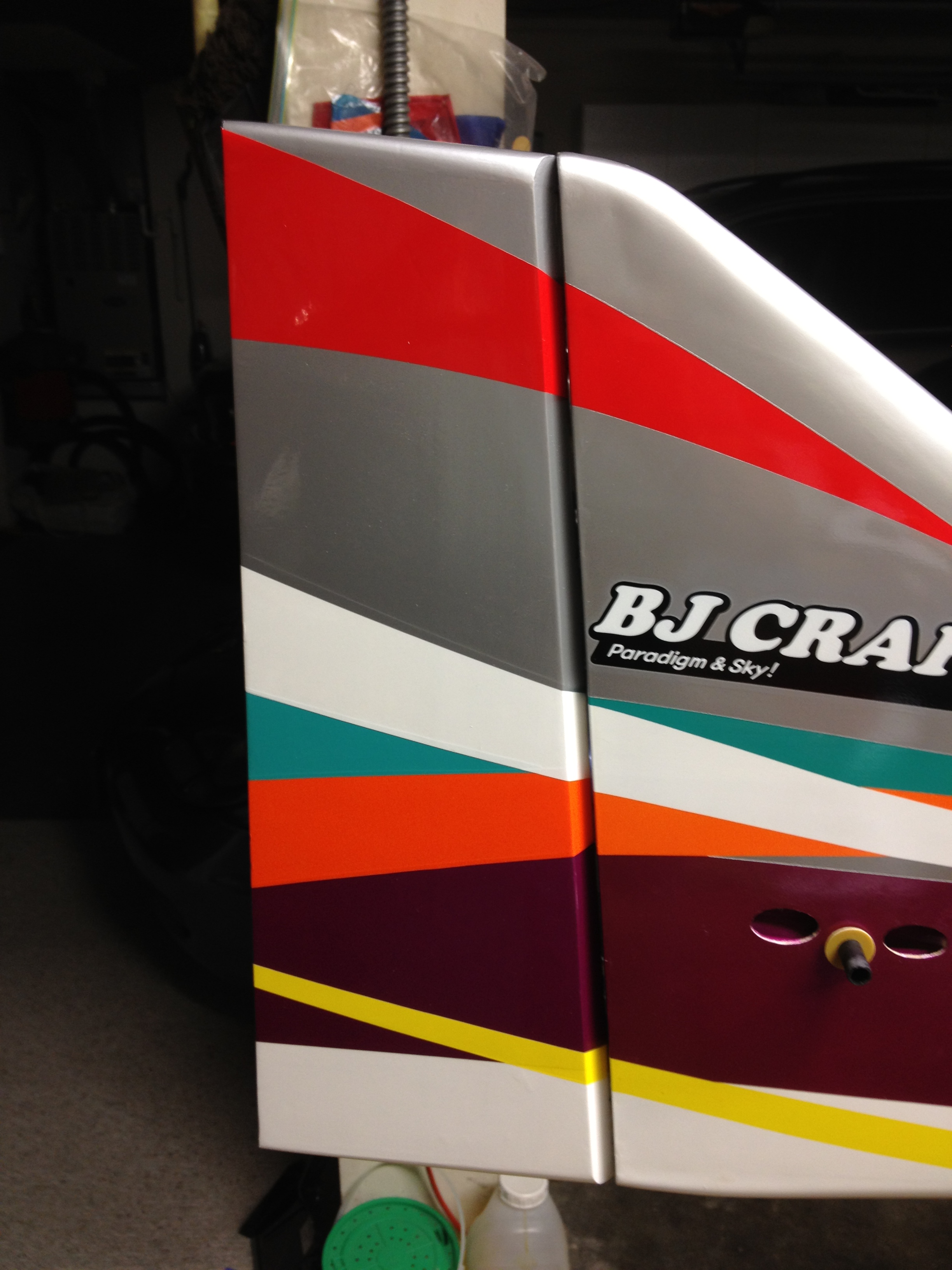
one point for me to the painting of the fuselage. At the top you have "silver colour". For my point of view "silver" in the air is not good; you will have reflexions/blinkings from the sun and "silver" will give no good visible view/line for pilot and judge.
We just had it with the Seba MythoS 2x2 m; at the buttom is red with silver and gold stripes. Depending on the sun in every roll combination the silver strips under the wing is blinking and giving reflexions. So I removed all this strips and did 3 normal whites stripes at the tipp of the wings and as well stab. Now no reflexions from the sun and the 3 white strips makes the plane better visible and gives a better line in the air,
Silver or gold colours are for my point of view no good colours; looking fine at the ground, but making some troubles in the air (sun reflexions etc.) for pilots AND judges.
I think the fixing of the top wing only with one srew is not a perfect solution, even if there were no problems during the test flights. The actuall modification is ... mmmhhh... a smal step in the correct way. The best way is - as at all F3A biplanes - to fix the top wing with two srews at the fuselage. But this is only my personal opinion.
Anyway a really interesting plane.
Corresponding the speed controller:
we are using the Jeti DC-16 together with the Hacker Q80 (Falcon Prop) and the Mezon 95 speed controller; the stuff works great and really fantastic to programm the Mezon whireless via the Jeti DC-16 TX and having all datas (rpm, ampere, voltage, temperature etc.) at the display of the Jeti DC-16 and if you want to have all this datas comming via voice announcement.
Also we have set a voice alarm to 4000 mA (10s battery is Hacker 4500 EcoEx); so if reaching 4000 mA, the Jeti TX says "alarm 4000 mA).
A really perfect combination !
Regards
PW
www.jeti-forum.de
Last edited by P. Wessels; 08-14-2013 at 11:08 PM.
08-15-2013 | 09:43 AM
#156
My Feedback: (45)
Arch
08-15-2013 | 09:59 AM
#158
Joined: Mar 2006
Posts: 325
Likes: 0
Received 0 Likes
on
0 Posts
From: Houston,
TX
FedEx came by yesterday had an extra box that didn't want to take back so they left it with me.
Here is what I found inside:
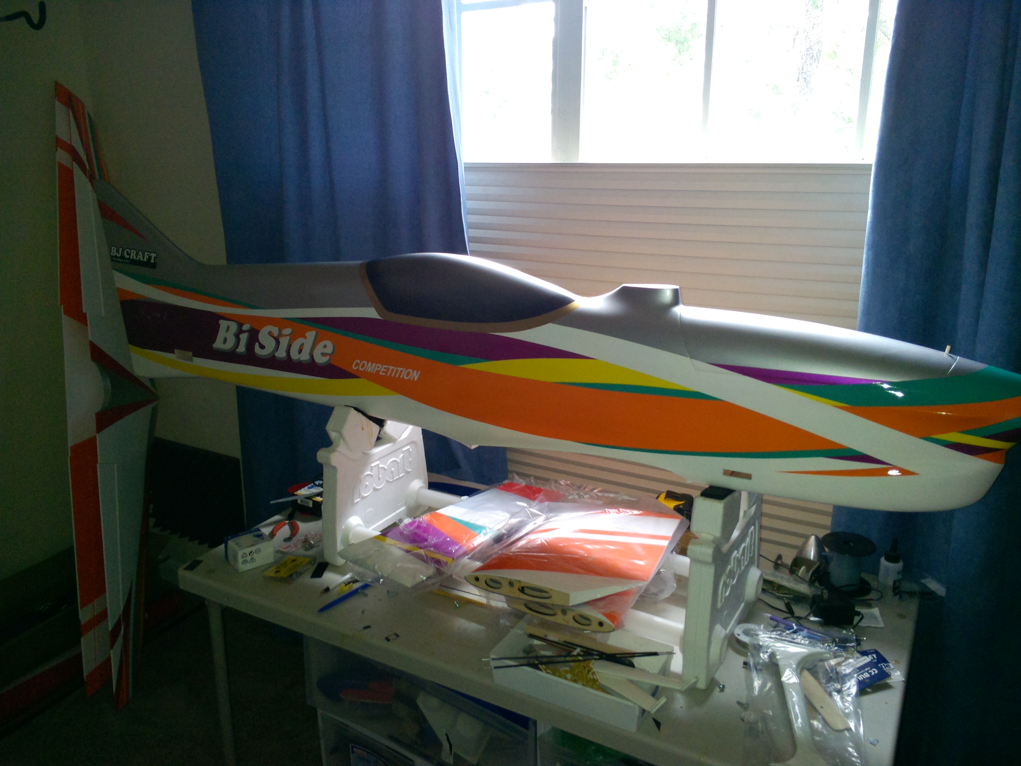
Here are the weight:
Fuselage: 959
Top wing: 377
Bottom wing: 381
Left ele: 74
Right ele: 70
Rudder: 51
All Harware: 330 (struts, landing gear: wheel pants, pushroads, control horns, etc)
Total ARF weight: 2242
Here is what I found inside:
Here are the weight:
Fuselage: 959
Top wing: 377
Bottom wing: 381
Left ele: 74
Right ele: 70
Rudder: 51
All Harware: 330 (struts, landing gear: wheel pants, pushroads, control horns, etc)
Total ARF weight: 2242
08-15-2013 | 11:32 AM
#159
My Feedback: (41)
FedEx came by yesterday had an extra box that didn't want to take back so they left it with me.
Here is what I found inside:
Here are the weight:
Fuselage: 959
Top wing: 377
Bottom wing: 381
Left ele: 74
Right ele: 70
Rudder: 51
All Harware: 330 (struts, landing gear: wheel pants, pushroads, control horns, etc)
Total ARF weight: 2242
Here is what I found inside:
Here are the weight:
Fuselage: 959
Top wing: 377
Bottom wing: 381
Left ele: 74
Right ele: 70
Rudder: 51
All Harware: 330 (struts, landing gear: wheel pants, pushroads, control horns, etc)
Total ARF weight: 2242
08-15-2013 | 12:36 PM
#160
My Feedback: (45)
Probably both. Very interested to really have some time on one of these. I played with the one at the NATS for a minute and it clearly flew well. Once again, like the Episode, the is most likely an FAI airplane. Masters maybe, but other than that, the rudder is very effective. Looks cool though. I definitely want one to play with and see what I think. Couldn't be happier with my Episode currently. Number 2 should be ready to fly in a week or so.
Arch
08-15-2013 | 02:34 PM
#162
Joined: Mar 2006
Posts: 325
Likes: 0
Received 0 Likes
on
0 Posts
From: Houston,
TX
Dana,
Probably both. Very interested to really have some time on one of these. I played with the one at the NATS for a minute and it clearly flew well. Once again, like the Episode, the is most likely an FAI airplane. Masters maybe, but other than that, the rudder is very effective. Looks cool though. I definitely want one to play with and see what I think. Couldn't be happier with my Episode currently. Number 2 should be ready to fly in a week or so.
Arch
08-15-2013 | 04:37 PM
#164


My Feedback: (8)
[QUOTE] Originally Posted by MTK
This electric stuff is sounding more and more complex every day. Whatever happened to kiss--ing your equipment? (Awright now, remove the innuendo!! LOL)
I mean, why all of this incompatibility??
[\QUOTE]
[QUOTE]
Certainly no more difficult Matt than matching the right motor to the right pipe. As some new stuff comes out, some people have to make some updates. The Castle stuff has been bullet proof with everything else. They are working to make it work with this one motor and they will have it sorted out soon.
Arch[\QUOTE]
It is as simple as you want to make it. Nothing says you can't use Lipo power packs and a 4.8v nickel Rx pack without a regulator. Maybe there are more things to mess with on electric? I don't know - what about a glow engine, pump, and a servo actuated mixing valve for the motor/pump? I've seen those!
Edit: probably better for it's own post
Last edited by Jetdesign; 08-15-2013 at 04:40 PM.
08-16-2013 | 07:57 AM
#166
Thread Starter
My Feedback: (5)
Sorry for the delay in posting build info. I was going to fit the firewall next but I ran into a snag with my new motor. The prop nut/bolt was seized in the prop shaft. There was absolutely no way to get it out. So, it went back into the container and I am waiting for instructions from Plettenberg.
Back to the tail assembly. I forgot to upload the final pics for flying stab mounting. The remainder of the job is very straight forward.
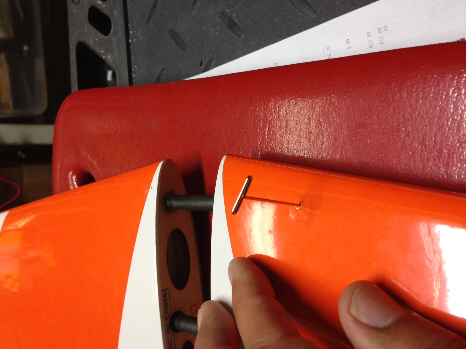
- assemble the stab halves with tubes. I checked the tube alignment with the pre-installed hard point in the LE of the stab. It looked like it was right in line with the center of the tube. No surprise there.
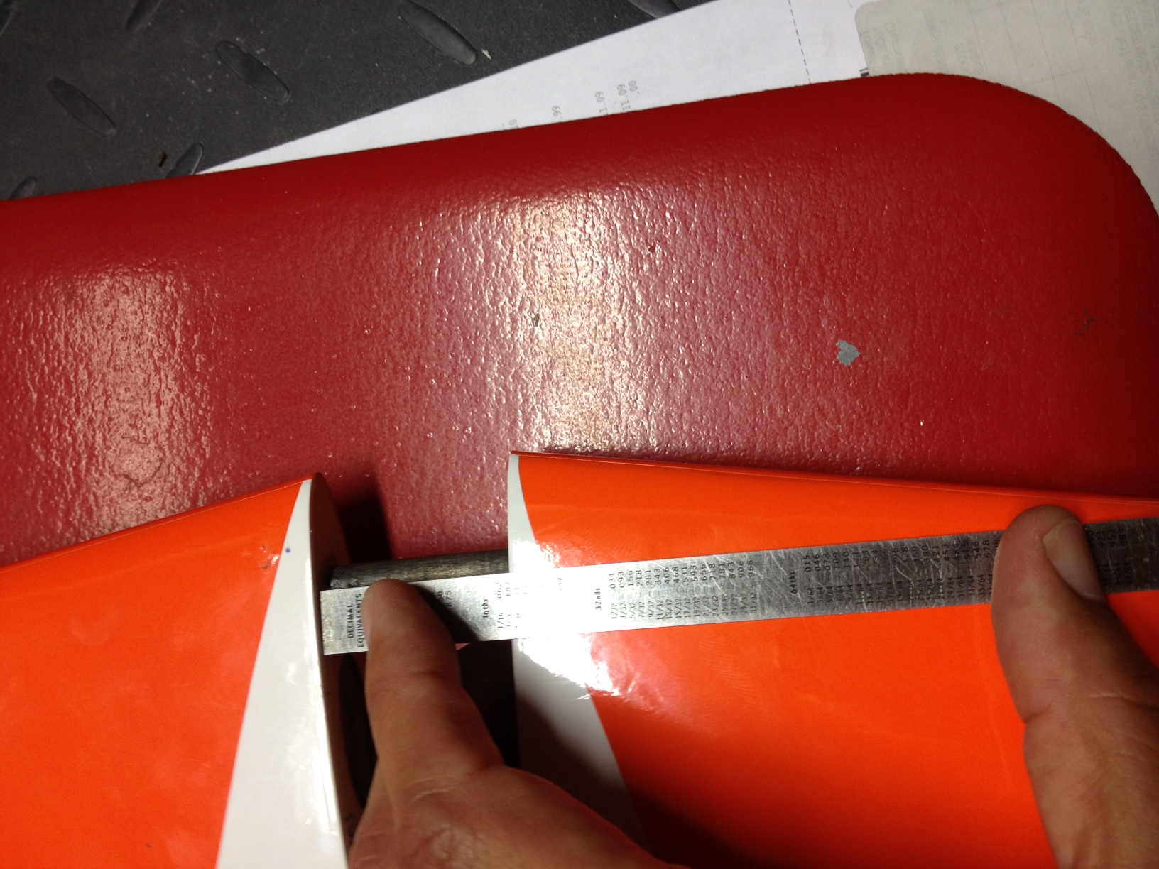
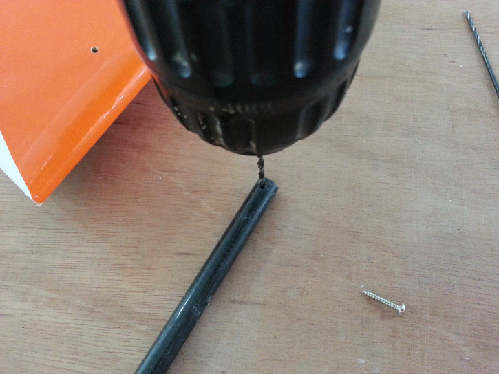
- Next I inserted a T Pin at the proper angle through the hardpoint and into the CF tube on the stab. This will give a bit of a score on the tube so that when you drill it the bit won't walk around at all.
- Then, drill through the tube. I checked the alignment prior to drilling into the stab tube
.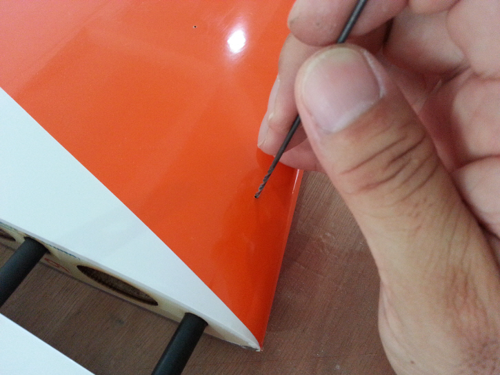
- Finally, clean up the tube hole and then install the supplied screw. That's it.
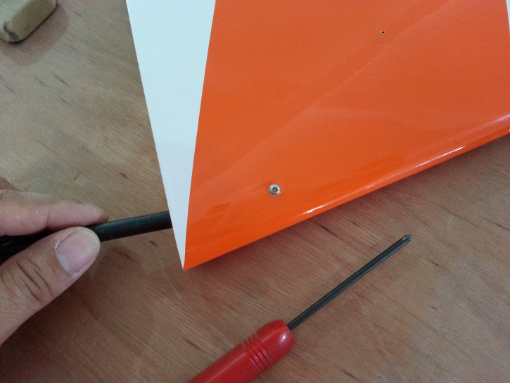
I also mounted the rudder. Check the hinge locations. I had to move a couple of them slightly to make sure it was centered. I use Great Planes CA hinges rather than the supplied hinges. Just a personal preference of mine.
Back to the tail assembly. I forgot to upload the final pics for flying stab mounting. The remainder of the job is very straight forward.
- assemble the stab halves with tubes. I checked the tube alignment with the pre-installed hard point in the LE of the stab. It looked like it was right in line with the center of the tube. No surprise there.
- Next I inserted a T Pin at the proper angle through the hardpoint and into the CF tube on the stab. This will give a bit of a score on the tube so that when you drill it the bit won't walk around at all.
- Then, drill through the tube. I checked the alignment prior to drilling into the stab tube
.
- Finally, clean up the tube hole and then install the supplied screw. That's it.
I also mounted the rudder. Check the hinge locations. I had to move a couple of them slightly to make sure it was centered. I use Great Planes CA hinges rather than the supplied hinges. Just a personal preference of mine.
08-16-2013 | 11:06 AM
#168
Thread Starter
My Feedback: (5)
I probably won't bother with stab bags since I never take them off. But I'll see if my wife will make me some wing bags. She made me a set for my Nuance (standard and DTFS) out of some quilted type material. So, since she has the hang of it maybe she can make these as well.
 08-19-2013 | 07:21 PM
#170
Thread Starter
My Feedback: (5)
Wow, you work a lot faster than I do... or you have a lot more time.... Ha Ha
As for my construction: I completed the motor installation activity. That is always my least favorite part of building a new plane. The mount fabrication was pretty easy since it is basically circular in shape. I am installing the Plettenberg Advance 30-10 so the procedure is pretty similar to what I did for the Episode. However the size of the mount is different since the Bi Side nose is a bit larger. It is sized for a 3” spinner.
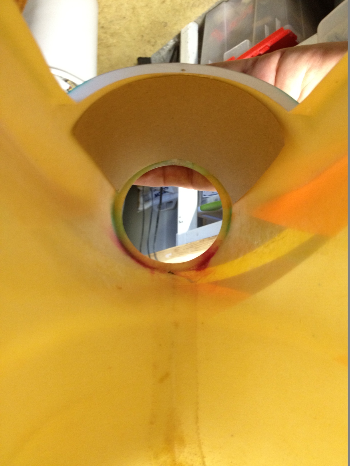
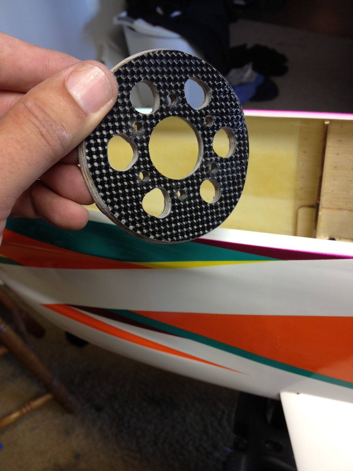
The steps I took are as follows
- First make a cardboard template just to check the diameter required. I cut two pieces of cardboard so that I would have a thickness close to the 3/16” plywood I am using. The front cardboard template was 82mm and the rear was 85mm.
- Next I cut out the plywood mount and cut the cooling holes. I used the 40mm bolt circle template for drilling the 4mm mounting bolt holes and the 27mm center cutout. I have a PDF of the bolt circle template (not the full motor mount, just the bolt pattern) for anyone that is interested, but I can't figure out how to attach the PDF to this thread. You can PM me.
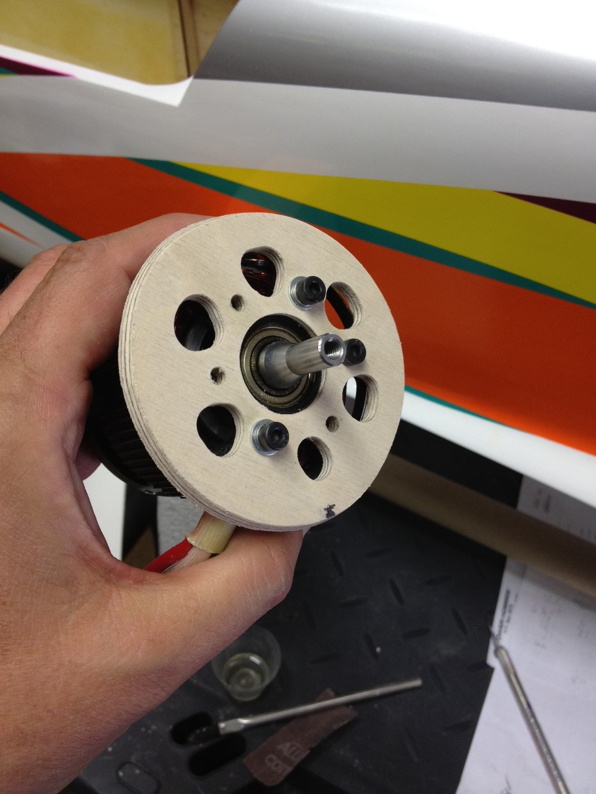
- As I was installing and fitting the mount I noticed that the nose had a bit more flex than the Nuance or Episode. So I elected to add some CF reinforcing. B.J. said that he did not do this on his Neu powered prototype. But the Plettenberg is going to be hard mounted and it has a larger rotor than the Neu so I felt it might be wise to beef up the nose a bit. I would extend the reinforcing if running a Hacker Q80 or other outrunner. I installed 3oz CF from the hatch to nose and then some strips running down to the chin. It really firmed it up. In order to fit the piece to the nose I made a template out of paper and used it to cut the CF mat. That helped a lot.
- I finished the fitting of the firewall then laminated it with CF
- Next I mounted the motor to the firewall and finished the fitting. Then I tacked it in with some CA The CF reinforcement looks ugly, but it will do the job.
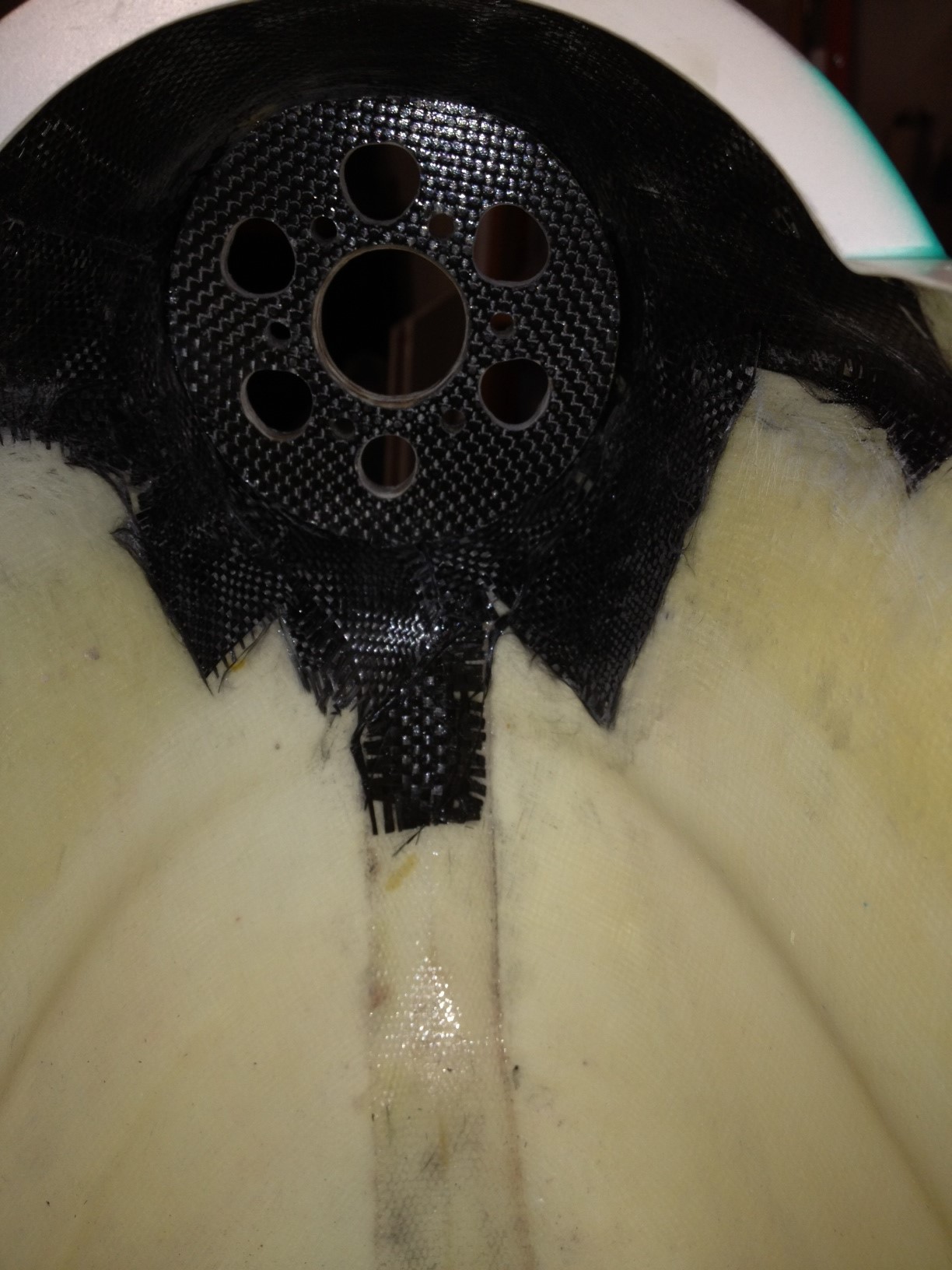
- Lastly, I added the Aeropoxy fillet to the front and backside of the firewall.
I hope to have mine in the air next weekend, that is if I can get out of work at a reasonable hour every night and put in an hour or so. The major stuff is done so now it is a matter of installing control horns and servos and the rest of the gear.
As for my construction: I completed the motor installation activity. That is always my least favorite part of building a new plane. The mount fabrication was pretty easy since it is basically circular in shape. I am installing the Plettenberg Advance 30-10 so the procedure is pretty similar to what I did for the Episode. However the size of the mount is different since the Bi Side nose is a bit larger. It is sized for a 3” spinner.
The steps I took are as follows
- First make a cardboard template just to check the diameter required. I cut two pieces of cardboard so that I would have a thickness close to the 3/16” plywood I am using. The front cardboard template was 82mm and the rear was 85mm.
- Next I cut out the plywood mount and cut the cooling holes. I used the 40mm bolt circle template for drilling the 4mm mounting bolt holes and the 27mm center cutout. I have a PDF of the bolt circle template (not the full motor mount, just the bolt pattern) for anyone that is interested, but I can't figure out how to attach the PDF to this thread. You can PM me.
- As I was installing and fitting the mount I noticed that the nose had a bit more flex than the Nuance or Episode. So I elected to add some CF reinforcing. B.J. said that he did not do this on his Neu powered prototype. But the Plettenberg is going to be hard mounted and it has a larger rotor than the Neu so I felt it might be wise to beef up the nose a bit. I would extend the reinforcing if running a Hacker Q80 or other outrunner. I installed 3oz CF from the hatch to nose and then some strips running down to the chin. It really firmed it up. In order to fit the piece to the nose I made a template out of paper and used it to cut the CF mat. That helped a lot.
- I finished the fitting of the firewall then laminated it with CF
- Next I mounted the motor to the firewall and finished the fitting. Then I tacked it in with some CA The CF reinforcement looks ugly, but it will do the job.
- Lastly, I added the Aeropoxy fillet to the front and backside of the firewall.
I hope to have mine in the air next weekend, that is if I can get out of work at a reasonable hour every night and put in an hour or so. The major stuff is done so now it is a matter of installing control horns and servos and the rest of the gear.
Last edited by shannah; 08-19-2013 at 07:23 PM.

