


First ever Simmer 600 build on RCU!!!
 03-30-2015 | 05:07 PM
#1

Thread Starter
Senior Member
Joined: Dec 2008
Posts: 164
Likes: 0
Received 0 Likes
on
0 Posts
From: Blackstock, SC
Rynchops Niger ~ Black Skimmer
https://www.youtube.com/watch?v=Ek_oL-Qq6fM&t=100
 Soarus Electricus ~ Electric Glider (RC)
https://www.youtube.com/watch?v=Ek_oL-Qq6fM&t=100
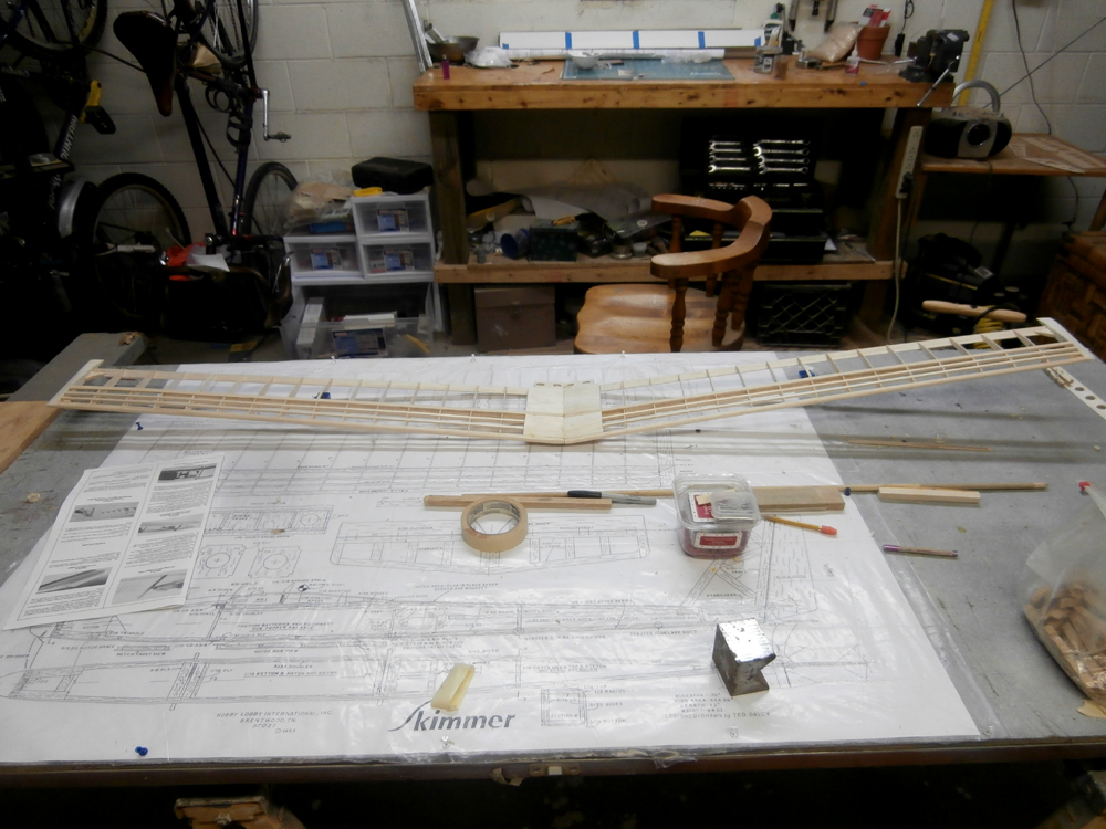
Soarus Electricus ~ Electric Glider (RC)According to the search function, there isn't a single Skimmer 600 build thread anywhere in RCUniverse! Or for that matter, a build thread of any size Skimmer (at least not of the aircraft)! So I guess this is the first build thread of this plane here.

This isn't the first Skimmer I've built though, I made the 400 version some years back, but my dog found it before I could maiden her. I'll spare you the gory details, but safe to say it wasn't repairable (All the King's horses and all the King's men...:sad
 . This one will be her larger brother, the Skimmer 600. This is the bird I should have made back then. I can already see it is going to be a lot easier, if only because there is a lot more room inside, and moving things around is going to be a lot easier.
Naturally, it will be modified. instead of the large 600 can motor I will be using a modern brushless (almost four times smaller!) the 6-7 nickel cells which normally sit under the wing will be replaced with a LiPo pack, which I can fit just about anywhere. As the plane is designed and balanced for a much larger and heavier motor I will probably be moving the pack forward, hopefully right behind the smaller brushless. That motor will be a Hyperion Zs2213 series outrunner. Batteries will be a 11.1V 1300MAH LiPo, (Mfg. rated at 30C).
I will also be lightening this bird as much as possible, mostly in the tail, as I need to re-balance the now lighter nose anyway. The lumber that came in the box is certainly not contest grade (thank goodness, I tried working with that dried sea foam on another plane!
 ), but is good enough. A least to me barely trained eye.
 ops: The solid pieces, like the rudder, elevator and tapered TE pieces will be drilled out, the clumsy 1/4 Sq. balsa pushrods replaced with modern, 'streamlined' .070 carbon rods. These may not be that much lighter, but they will make installation a lot easier. Advertised weight for this bird is 44oz. Wing Loading @ 12 oz./ft. MotoCalc tells me with just the new motor and batteries it will already be much lighter; 33oz AUW, 9 oz/ft WL. Hopefully I will be able to beat even that.
Other mods will be on the main wing, which as designed is a 70" (1.8M) single piece dihedral. Almost as long as my truck bed, which as I don't have a cover for it is probably not the best place store an RC sailplane wing while transporting this bird to the field. So I will be breaking it into two pieces. Also I will be replacing the 1" x 35" tapered trailing edge piece with a 1.25" x 35" tapered TE which will be cut and hooked up with servos to give me camber/reflex control, or 'CambFlex' (hey, it's better than "Refer"
 >). Since both control surfaces will be working in unison they will be connected to the same channel (5) via a reversing Y harness. These will not be ailerons, The basic controls will remain as designed; Rudder/Elevator/Throttle. They will not be flaps or spoilers (although they can easily be modified to provide such). I hear flaps are pretty much useless on this plane anyway. http://www.rcgroups.com/forums/showt...ps#post4044841
Last edited by FlyWheel; 04-01-2015 at 04:20 AM. Reason: speling airer in tytel
 03-30-2015 | 05:14 PM
#2
Thread Starter
Senior Member
Joined: Dec 2008
Posts: 164
Likes: 0
Received 0 Likes
on
0 Posts
From: Blackstock, SC
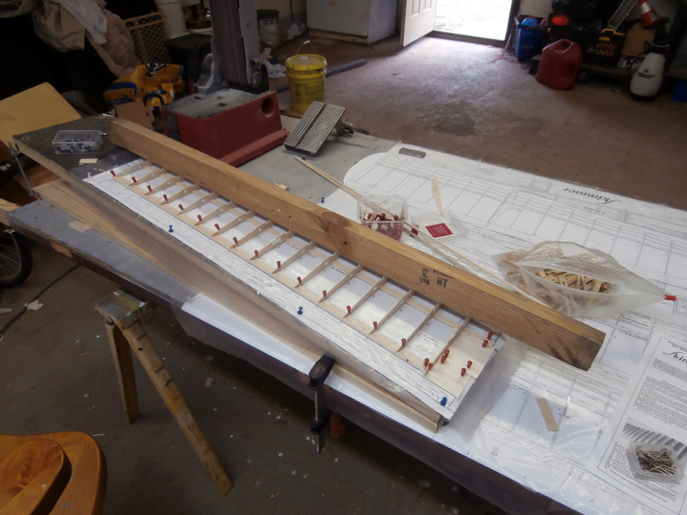
The instructions say to start with the wing, but I am intending to build a special jig for building that so I decided to start with the tail feathers instead. Nothing in their basic construction requires that something else be built first, and seeing as they are the simplest part anyway, it seems a good route on the way to getting my hands dusty again.
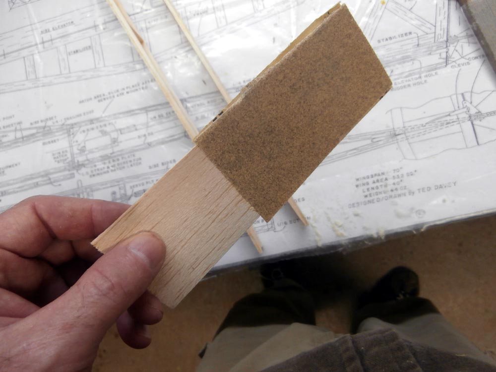
First thing I did was to plane the TE taper in the rudder and elevator pieces. Then I got the hole saws I bought and start drilling them out. I found the hole saws worked best when I screwed the pilot drill into the proper size and then used them as hand tools, twisting them back and forth slowly boring until I was halfway through one side, then turning the piece over and using the same pilot hole to cut the rest of the way through from that side. Doing it this way resulted in a nice clean hole with a minimum of feathering left in the wood, What little there was was easily sanded away with some 220 grit sandpaper.
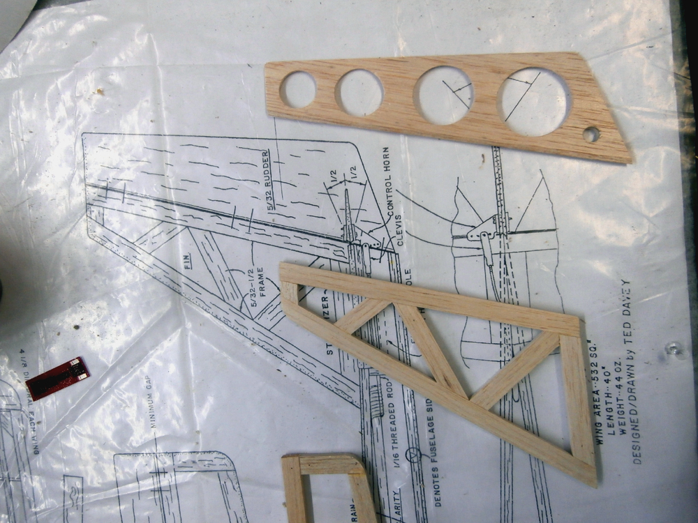
Unfortunately the hole saw set I bought only went down to 1" diameter, which was too big for the elevator pieces. So I am going to have to find something smaller. Say 1/2". I didn't get to the 1.25" tapered TE pieces drilled out; I'm really not sure if I should use the 1" hole saw on that anyway (perhaps a 1/2" or 3/4"?). Or for that matter if I should even drill those out at all! The full span of the 'CambFlexer' pieces are over 31" long, and even with the control horn mounted at the center that makes for a long span to be full of holes.
I did get the horizontal and vertical tailfins built up though. Once they are cured i will sand them to shape. Last thing I did was to put the elevators together with the bent music wire connector piece. I could have used CF, but after weighing the steel piece and a short piece of cf tubing that was even bigger that what I would have used i found both weighed less than 1 gram (the least my postage scale could detect), so I figured any weight difference would be so negligible as not to be worth the effort. So I epoxied the music wire in place.
First thing I did was to plane the TE taper in the rudder and elevator pieces. Then I got the hole saws I bought and start drilling them out. I found the hole saws worked best when I screwed the pilot drill into the proper size and then used them as hand tools, twisting them back and forth slowly boring until I was halfway through one side, then turning the piece over and using the same pilot hole to cut the rest of the way through from that side. Doing it this way resulted in a nice clean hole with a minimum of feathering left in the wood, What little there was was easily sanded away with some 220 grit sandpaper.
Unfortunately the hole saw set I bought only went down to 1" diameter, which was too big for the elevator pieces. So I am going to have to find something smaller. Say 1/2". I didn't get to the 1.25" tapered TE pieces drilled out; I'm really not sure if I should use the 1" hole saw on that anyway (perhaps a 1/2" or 3/4"?). Or for that matter if I should even drill those out at all! The full span of the 'CambFlexer' pieces are over 31" long, and even with the control horn mounted at the center that makes for a long span to be full of holes.
I did get the horizontal and vertical tailfins built up though. Once they are cured i will sand them to shape. Last thing I did was to put the elevators together with the bent music wire connector piece. I could have used CF, but after weighing the steel piece and a short piece of cf tubing that was even bigger that what I would have used i found both weighed less than 1 gram (the least my postage scale could detect), so I figured any weight difference would be so negligible as not to be worth the effort. So I epoxied the music wire in place.
03-31-2015 | 02:44 PM
#3
Thread Starter
Senior Member
Joined: Dec 2008
Posts: 164
Likes: 0
Received 0 Likes
on
0 Posts
From: Blackstock, SC
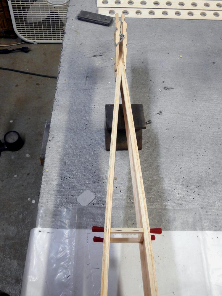
This will not only let me construct the wings with washout built in, but will also let me accurately set the dihedral angle. I made it a bit bigger than necessary for this bird so it can accommodate larger wing sections in the future. Each side measures 10" x 48" and can be unfolded (completely flat if necessary) to accommodate two wing sections. It was fabricated from two 1" x 10" x 48" pieces of pine, a continuous hinge cut to 10", four 1/2" corner brackets, Two 1/4-20 x 8" carriage bolts, six 1/4-20 nuts and of course the pin-board and assorted wood screws. Construction is simple and straightforward enough that anyone should be able to copy the design from the photos.


Last edited by FlyWheel; 03-31-2015 at 02:46 PM. Reason: Added title
04-03-2015 | 02:58 PM
#6
Thread Starter
Senior Member
Joined: Dec 2008
Posts: 164
Likes: 0
Received 0 Likes
on
0 Posts
From: Blackstock, SC
I started the day (after my morning dose of caffeine, of course) with a trip to the Church of Our Lady of Miniature Vehicles, A.K.A. The Hobby Shop to get some .250" thin walled brass tubing to cut some holes in the ribs. Turns out they also had some larger sizes too. No .500", but they did have .625" so I got a short tube of that too. I guess I won't have to go searching at Lowe's or Michael's or Hobby Lobby for something to cut the midsize circles with. I Also got a pair of .750 tapered TE pieces for, well, the wing's trailing edge. Unfortunately all they had this in was "hard" balsa. Oh well. I also traded in one of the 1.250 tapered pieces I had gotten for the Cambflexers, as I noticed it was unstraightenably* warped. Proprietor said no problem. As he also sold UltraCote I asked him to order a couple of rolls each in the two colors that he didn't have in stock for the plumage that I plan to dress this bird in.
I'm still wondering if I should cover the fuse or just paint it? I have the color paints I wish to use.
I used a round file to sharpen one end of both the .250" and .625" TW tubes. I cut the .250 into a shorter piece as it was small enough that it could be chucked into my drill. I used it to bore the holes for the servo wires through the set of ribs with the spar slots lined up with a short piece of spruce. I will have to widen some of these to allow the plug to pass through, obviously. Once drilled I used that hole to clamp them all together with a 1/4-20 bolt and wing-nut so I could shape and sand out the irregularities of the die cut (which were rather nice, I might add, I guess the dies were sharp for this batch of wood).


I then marked the 1.250 cambflexers and used the .625" TWB tube as a hand 'hole saw' to drill it out. When I was finished I didn't notice any significant lessening in stiffness, so I guess with the covering they should work fine. Exactly how much lighter they will be I have no idea, all the 'holes' didn't weight much. Then again 1 penny isn't that much either, but enough pennies all together will buy you a house, right?


Last thing I did was to cut and file notches into the .750 TE and cut and trim the ends of the ribs to fit. At least those for the left wing.
Who knows? Tomorrow I may actually be able to start gluing it together.!
*Yes that's a real word. Because I typed it and I say it is!
I Also got a pair of .750 tapered TE pieces for, well, the wing's trailing edge. Unfortunately all they had this in was "hard" balsa. Oh well. I also traded in one of the 1.250 tapered pieces I had gotten for the Cambflexers, as I noticed it was unstraightenably* warped. Proprietor said no problem. As he also sold UltraCote I asked him to order a couple of rolls each in the two colors that he didn't have in stock for the plumage that I plan to dress this bird in. I'm still wondering if I should cover the fuse or just paint it? I have the color paints I wish to use.
I used a round file to sharpen one end of both the .250" and .625" TW tubes. I cut the .250 into a shorter piece as it was small enough that it could be chucked into my drill. I used it to bore the holes for the servo wires through the set of ribs with the spar slots lined up with a short piece of spruce. I will have to widen some of these to allow the plug to pass through, obviously. Once drilled I used that hole to clamp them all together with a 1/4-20 bolt and wing-nut so I could shape and sand out the irregularities of the die cut (which were rather nice, I might add, I guess the dies were sharp for this batch of wood).
I then marked the 1.250 cambflexers and used the .625" TWB tube as a hand 'hole saw' to drill it out. When I was finished I didn't notice any significant lessening in stiffness, so I guess with the covering they should work fine. Exactly how much lighter they will be I have no idea, all the 'holes' didn't weight much. Then again 1 penny isn't that much either, but enough pennies all together will buy you a house, right?
Last thing I did was to cut and file notches into the .750 TE and cut and trim the ends of the ribs to fit. At least those for the left wing.
Who knows? Tomorrow I may actually be able to start gluing it together.!
*Yes that's a real word. Because I typed it and I say it is!
04-05-2015 | 02:57 PM
#7
Thread Starter
Senior Member
Joined: Dec 2008
Posts: 164
Likes: 0
Received 0 Likes
on
0 Posts
From: Blackstock, SC
I did a bike ride yesterday and had to mow the lawn this morning, so I didn't get back into the shop until 2 PM today.
Ok, First there's maybe a little more cutting, drilling, shaping and sanding that needs to get done before I can get out the glue. First thing I did was to get out my 5/8" TWB hole saw and put some holes into the elevator (forgot to do that the other day when I did the cambflexers ).

Also used the #1 rib that came with the kit as a template to make a pair of light ply copies. Normally the two 1/16" balsa ribs at the wing center get laminated together in the construction of the wing as a single piece. But I'm not making this wind as a single piece, so those two ribs are not going to be laminated. Therefore I'm substituting light ply to make up for the lack of strength.
 The violet tube is the substitute for the plywood dihedral brace (also shown) that would have been glued in place. Most people use brass for this, but I found an alumini(u)m Heli boom that is just as stiff, if not stiffer, and it's also much lighter than brass. Heck, it's even a whole gram lighter than the plywood brace it's replacing.
I had a little trouble with the wing, my fault really; I pinned the rear spar too far back and didn't realize this until everything was pinned in place and the glue had almost dried So I had to remove it, shorten the back end of the ribs while still glued to the rest of the structure, re-notch the spar and re-glue it all back together. As such I was only able to get the bottom half of the left wing done.
Ok, First there's maybe a little more cutting, drilling, shaping and sanding that needs to get done before I can get out the glue. First thing I did was to get out my 5/8" TWB hole saw and put some holes into the elevator (forgot to do that the other day when I did the cambflexers
).Also used the #1 rib that came with the kit as a template to make a pair of light ply copies. Normally the two 1/16" balsa ribs at the wing center get laminated together in the construction of the wing as a single piece. But I'm not making this wind as a single piece, so those two ribs are not going to be laminated. Therefore I'm substituting light ply to make up for the lack of strength.
I had a little trouble with the wing, my fault really; I pinned the rear spar too far back and didn't realize this until everything was pinned in place and the glue had almost dried
So I had to remove it, shorten the back end of the ribs while still glued to the rest of the structure, re-notch the spar and re-glue it all back together. As such I was only able to get the bottom half of the left wing done.
04-06-2015 | 05:16 AM
#9
Thread Starter
Senior Member
Joined: Dec 2008
Posts: 164
Likes: 0
Received 0 Likes
on
0 Posts
From: Blackstock, SC
Balsa, for all it's strength to weight benefits is also a very brittle wood. It doesn't mind sharp cutting blades but will shred if attacked with anything with anything but the finest of teeth; that's why razor saws have such fine teeth. I use a round file to sharpen one end of the tube, but don't strop the edge, instead leaving the fine serrations making them, in effect circular razor saws. The only real drawback is I do have to periodically re-file the edge back in as brass is not a real hard metal and dulls fast.
Smaller ones I can chuck up in my drill for boring through real thick wood or thick stacks. For larger holes I just turn it with my hands, easing up as it starts to break through, or even turning the wood over and finishing the cut through the 'back'. The regular hole saws I used for the rudder I turned by hand for better control. The holes do not end up as clean as they look in the pictures, there is a little feathering, but that is easily sanded clean.
P.S. It is a kit that I am modifying (the original design is just RET). The Skimmer has always to my knowledge been a kit, but hasn't been manufactured for years now. http://aerocraftrc.com made them for Hobby Lobby at first.
Last edited by FlyWheel; 04-06-2015 at 03:41 PM.
04-06-2015 | 03:31 PM
#10
Thread Starter
Senior Member
Joined: Dec 2008
Posts: 164
Likes: 0
Received 0 Likes
on
0 Posts
From: Blackstock, SC
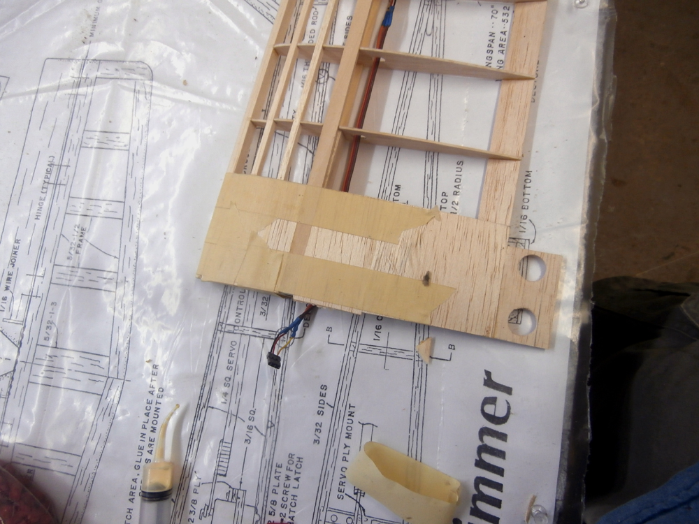
Anyone know if you can buy the triple wires used for servo leads? All I need is the wires, as the ones that came with the servo are to short! I know there are longer wings than this so there should be. Anyway, I also got the light ply mounting plate made for the servos and the door that will give me access to the servos made up. I'll attach them when I get the top spar done.

I also got the two turbulators glued onto the front of the wing. Yeah, I know. They're not really turbulators, but that's what they call them.") I used a long 2x3 piece of fir to clamp them down while the glue dried. In the meantime I got out the tail feathers and sanded them to shape.
I used a long 2x3 piece of fir to clamp them down while the glue dried. In the meantime I got out the tail feathers and sanded them to shape.


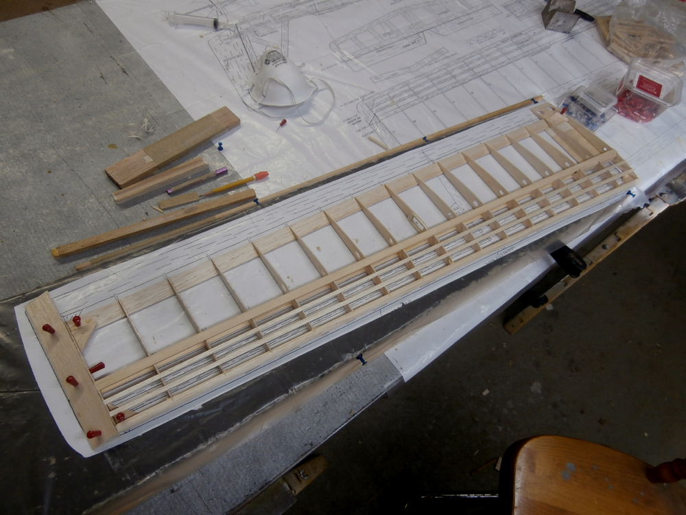
Here is the glued wing. The instructions say to attach the top spar and glue the shear webs onto the side of the spars, but I'm doing things a bit different. on this page at http://www.airfieldmodels.com it is claimed that the webs fit between the spars is stronger than when glued to the sides.it makes sense so I'm going to cut and fit each web on the center of each spar before gluing the top spar on. At the very least it will lighten the wing an itty bit because there will be a wee bit less glue and wood.
I also got the two turbulators glued onto the front of the wing. Yeah, I know. They're not really turbulators, but that's what they call them.
I used a long 2x3 piece of fir to clamp them down while the glue dried. In the meantime I got out the tail feathers and sanded them to shape.Here is the glued wing. The instructions say to attach the top spar and glue the shear webs onto the side of the spars, but I'm doing things a bit different. on this page at http://www.airfieldmodels.com it is claimed that the webs fit between the spars is stronger than when glued to the sides.it makes sense so I'm going to cut and fit each web on the center of each spar before gluing the top spar on. At the very least it will lighten the wing an itty bit because there will be a wee bit less glue and wood.
Last edited by FlyWheel; 04-06-2015 at 03:49 PM. Reason: Tring to get the $#@&% links to work right
04-06-2015 | 05:22 PM
#12

My Feedback: (-1)
I buy servo wire at Hobby People when it's on sale, most hobby shops stock it. I just clip the servo wire and solder in whatever length I need. I buy my shrink wrap tubes from Lowe's, I can buy packs of the sizes I want instead of the mixed sizes you find at radio shack. I have read of guys using phone extension cords but it looked too small to me.
04-07-2015 | 04:37 PM
#13
Thread Starter
Senior Member
Joined: Dec 2008
Posts: 164
Likes: 0
Received 0 Likes
on
0 Posts
From: Blackstock, SC
I buy servo wire at Hobby People when it's on sale, most hobby shops stock it. I just clip the servo wire and solder in whatever length I need. I buy my shrink wrap tubes from Lowe's, I can buy packs of the sizes I want instead of the mixed sizes you find at radio shack. I have read of guys using phone extension cords but it looked too small to me.
).I picked up some while my tenant was at her doctor's Appt. Thanks for the reply anyway though. Today I started by gluing some sandpaper around the scrap piece of the heli boom I used for the dihedral brace, and used it to sand a half circle groove in the sides of some balsa stock which I will laminate together to form a channel that will be fitted into the wing.
* * * * * * * * * * * * * * * *
When I got back from lunch I fitted in the #1 rib that I had made out of ply, using a right triangle to get the proper angle (the build board is already set at the correct dihedral - the wing tip 4-1/8" higher than the root as per the instructions).
Last but not least I trimmed off the ends of the spars and turbulators flush with the first and last ribs and left everything to cure completely. Tomorrow I will remove it from the jig.
Last edited by FlyWheel; 04-09-2015 at 01:33 PM. Reason: rotated image
04-09-2015 | 01:20 PM
#14
Thread Starter
Senior Member
Joined: Dec 2008
Posts: 164
Likes: 0
Received 0 Likes
on
0 Posts
From: Blackstock, SC
V Look familiar, Stu?
 I got the left wing off the board and shaped the LE, then glued on the tip piece.
Once it was dried I sanded it to shape using my belt sander, razor plane and sandpaper
Great. Now that the left wing is more or less done, all the mistakes have been made. I can now sit down and make the other wing correctly! I reset the warp in the board for the washout in the right wing and pinned down the plan under plastic. As I cut and shaped each one to fit, but before gluing them in place, I also traced out each of the ribs. I used the backside of the plan to do this (the remaining piece from the copy I cut up and am using for the wings) Now if (read: When) I crash I can cut out new ones!
Once it was dried I sanded it to shape using my belt sander, razor plane and sandpaper
Great. Now that the left wing is more or less done, all the mistakes have been made. I can now sit down and make the other wing correctly!
I reset the warp in the board for the washout in the right wing and pinned down the plan under plastic. As I cut and shaped each one to fit, but before gluing them in place, I also traced out each of the ribs. I used the backside of the plan to do this (the remaining piece from the copy I cut up and am using for the wings) Now if (read: When) I crash I can cut out new ones!
Last edited by FlyWheel; 04-09-2015 at 01:27 PM.
04-10-2015 | 01:29 PM
#15
Thread Starter
Senior Member
Joined: Dec 2008
Posts: 164
Likes: 0
Received 0 Likes
on
0 Posts
From: Blackstock, SC
Sometimes your way is the better way!
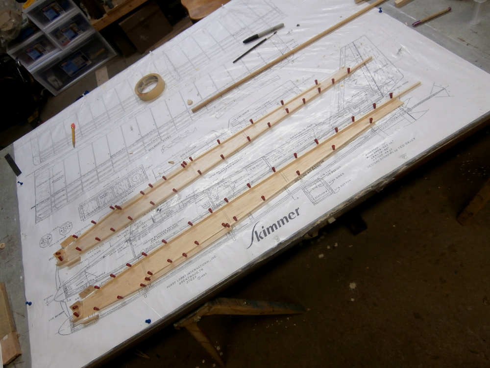
The instructions say to first put the trailing edge on the plan, mark then notch it where the ribs are. Then pin the bottom spar onto the plan and glue on all the ribs. Then sand the ends of the ribs to the same length, glue on the TE, then do the same for the front of the ribs and glue on the leading edge (which isn't notched). This IMO is a recipe for disaster. When I took the left wing off the plan I found that some of the ribs weren't even touching the LE! I had to carefully cut the glue and redo them using thin balsa shims.
Here's how I did the right wing, (after learning that their way doesn't work!)...
First I marked the trailing edge where the ribs were and notched it. Then I did the same for the leading edge and pinned it, the TE and the spar (all three) to the plan and cut, trimmed, sanded and installed each rib individually, so they all fit perfectly in place. The results, need I say are much nicer. The wing went together a lot nicer too.
04-11-2015 | 02:52 PM
#16
Thread Starter
Senior Member
Joined: Dec 2008
Posts: 164
Likes: 0
Received 0 Likes
on
0 Posts
From: Blackstock, SC
Started the day by picking up six (count em, six!) young chicks. As such I didn't get too much done on the plane. I did get the shear webs sanded and the top spar attached. Once they were sufficiently cured I planed and sanded the leading edge, root and tip ribs smooth and and put on the tip piece.
Oh, the chicks? They're doing fine. They're resting in their new home out back.
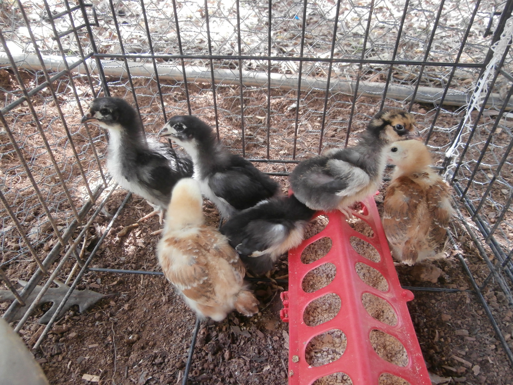
(What kind of chicks did you think I was talking about? )
Oh, the chicks? They're doing fine. They're resting in their new home out back.
(What kind of chicks did you think I was talking about?
)
04-14-2015 | 02:07 PM
#18
Thread Starter
Senior Member
Joined: Dec 2008
Posts: 164
Likes: 0
Received 0 Likes
on
0 Posts
From: Blackstock, SC
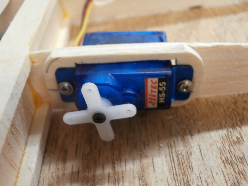
Today I soldered the extension wires onto the servos, fed them through the holes in the wing ribs and screwed in the servos. A drop of CA on the sheeting at the root holds the wires straight. I didn't bother with the soda straw trick, this looks Just as clean and I didn't have to figure out how I was going to solder the extensions on through the straws, as the joint is about halfway along the line (I couldn't find any straws wide enough for the three wires anyway ). I also installed a locating pin on the root rib to keep the two wings from twisting Re: to each other and sheeted the root section. Lastly I planed/sanded the 'leading edge' of the cambflexers. I'm going to use a 'UltraCote hinge' to hold them on the wing.


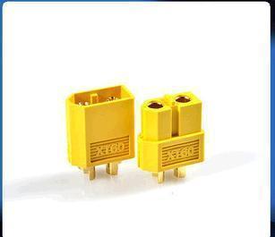
P.S. Is there a 'accepted standard' for soldering XT-60 connectors, like negative @ the pointy edge or something like that?
). I also installed a locating pin on the root rib to keep the two wings from twisting Re: to each other and sheeted the root section. Lastly I planed/sanded the 'leading edge' of the cambflexers. I'm going to use a 'UltraCote hinge' to hold them on the wing.P.S. Is there a 'accepted standard' for soldering XT-60 connectors, like negative @ the pointy edge or something like that?
Last edited by FlyWheel; 04-14-2015 at 02:11 PM.
04-16-2015 | 04:02 PM
#19
Thread Starter
Senior Member
Joined: Dec 2008
Posts: 164
Likes: 0
Received 0 Likes
on
0 Posts
From: Blackstock, SC
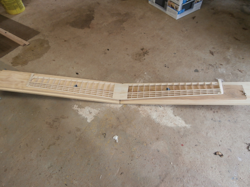
Finished the wings, sanding the sheeting down smooth with the root ribs. When I put them together they fit together nicely enough, with almost no gap, and after weighting one tip so that wing laid flat on the table the other tip measured at 8.125" from the table top. That's measured from chord center, I built in the washout, remember?  Normally they would have been epoxied together with each tip elevated 4.125", so it seems I'm off by about .125" (0.0625" per side). Close enough; I guess my dihedral fixture works.

Now for the fuselage...
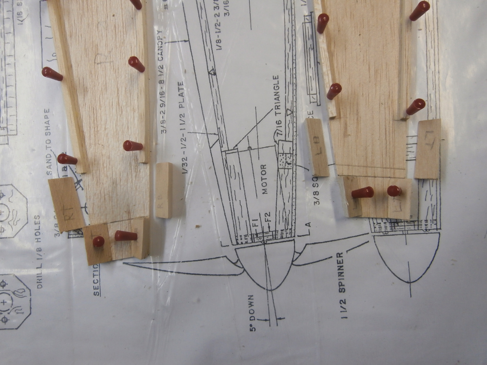
Construction of this starts with the large angle pieces at the nose. Normally these form a backing for the firewall which is mounted at the very front of the plane with the motor mounted behind that, the shaft sticking through. However I know from experience that not only does this leave damn little shaft left for the prop/spinner to grab onto, but it also makes for a fragile front end once all the shaping is done. So I am moving the firewall further back into the fuselage and mounting an outrunner to the front of it. This will make for a stronger mount, give the prop more shaft to clamp onto and as an extra bonus it will alleviate the problem of routing the wires around the spinning motor's bell housing.
 The rest of the triangle stock will be behind the plywood firewall, which obviously I will have to custom make as the pieces that came with the kit are now too small; these will be sandwiched in between the front and back pieces. I'm using plywood instead of an alumin(i)um 'X' mount so I can blend the front of the fuselage to match the round shape of the spinner. The remaining fuse section in front of the firewall will basically be a cowl.
 The rest of today's construction consisted of adding the 0.1875" Sq. stock that makes the inside corners of the fuselage, the wing cradle doublers and the two 'formers', which I personally think should actually be called bulkheads, as they don't 'form' anything; they only hold the two fuse sides apart and separate it into sections. You'll notice I have changed these slightly, the bottom of the front one has been removed as I will probably have to move the battery pack to balance the plane. Normally it sits under the wing right at the CoG, but because I'm not using the brushless outrunner I will probably have to move it forward.
I did this ->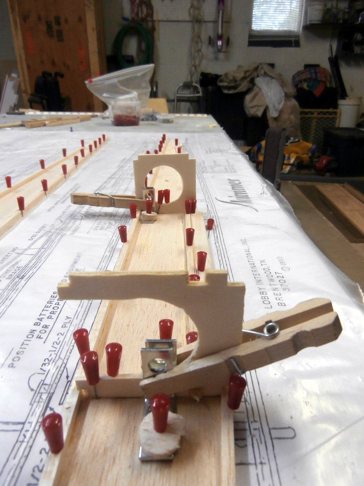
because this ->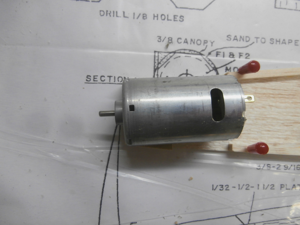 ...is being replaced by this ->
Removing the lower portion of the bulkhead will make balancing the plane easier in case the proper balance point puts the pack partway 'through' it. This section is not really needed as the latch for the removable bottom panel sits here and it will make up for the missing portion of the bulkhead.
That's it for today. my NSLHS (Not So Local Hobby Shop) called the other day, the covering I ordered is in. As I am headed up that way anyways I'm going to pick it up tomorrow along with some ply and more 0.1875 square stock, as it seems they didn't supply enough in the kit.
Normally they would have been epoxied together with each tip elevated 4.125", so it seems I'm off by about .125" (0.0625" per side). Close enough; I guess my dihedral fixture works. Now for the fuselage...
Construction of this starts with the large angle pieces at the nose. Normally these form a backing for the firewall which is mounted at the very front of the plane with the motor mounted behind that, the shaft sticking through. However I know from experience that not only does this leave damn little shaft left for the prop/spinner to grab onto, but it also makes for a fragile front end once all the shaping is done. So I am moving the firewall further back into the fuselage and mounting an outrunner to the front of it. This will make for a stronger mount, give the prop more shaft to clamp onto and as an extra bonus it will alleviate the problem of routing the wires around the spinning motor's bell housing.
I did this ->
because this ->
Removing the lower portion of the bulkhead will make balancing the plane easier in case the proper balance point puts the pack partway 'through' it. This section is not really needed as the latch for the removable bottom panel sits here and it will make up for the missing portion of the bulkhead.
That's it for today. my NSLHS (Not So Local Hobby Shop) called the other day, the covering I ordered is in. As I am headed up that way anyways I'm going to pick it up tomorrow along with some ply and more 0.1875 square stock, as it seems they didn't supply enough in the kit.
04-17-2015 | 02:56 PM
#20
Thread Starter
Senior Member
Joined: Dec 2008
Posts: 164
Likes: 0
Received 0 Likes
on
0 Posts
From: Blackstock, SC
The HS had my covering, but they came up one roll short on the transparent color. So I had them order another one JIC. Not sure I'll need it, but you know how these things come out: You always seem to need Just. Five. Inches. More... Also got some 3/16 square balsa* and 1/4 ply for an interior X-mount to replace the two 1/8 pieces that would have been laminated together and mounted on the front. After measuring and cutting the X-mount I used the alumin(i)um one that came with the motor to locate the mounting holes. Not the prettiest looking job I've done, but it's accurate. That done I started putting together the fuselage.


Once the glue was set I laminated some 100 grit sandpaper to both sides of a 1/8" sheet of balsa to sand the bevel into the tail, then glued and clamped them together.


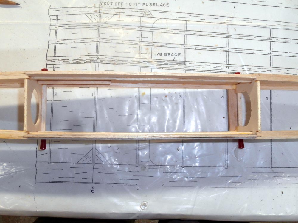
Lastly I added the cross braces and rails to hold the servo mounts. Actually, that part, amongst other things, probably should have been done before the fuse halves were joined (I guess that's what I get for reading the instructions! ). You'll notice the rails are mounted ahead of the rear bulkhead, instead of behind it (see plan in photo #2). This is partly for balance, but also the way 'they' had them mounted the servos would have been sealed under the rear turtledeck. This way I can get to them. Also note the piece of ply under the rear bulkhead, that is part of the latching mech. for the underside hatch (I told you the missing bottom of the BH would be taken care of! )

Once the glue was set I laminated some 100 grit sandpaper to both sides of a 1/8" sheet of balsa to sand the bevel into the tail, then glued and clamped them together.
Lastly I added the cross braces and rails to hold the servo mounts. Actually, that part, amongst other things, probably should have been done before the fuse halves were joined (I guess that's what I get for reading the instructions!
). You'll notice the rails are mounted ahead of the rear bulkhead, instead of behind it (see plan in photo #2). This is partly for balance, but also the way 'they' had them mounted the servos would have been sealed under the rear turtledeck. This way I can get to them. Also note the piece of ply under the rear bulkhead, that is part of the latching mech. for the underside hatch (I told you the missing bottom of the BH would be taken care of! )
04-17-2015 | 02:58 PM
#21
Thread Starter
Senior Member
Joined: Dec 2008
Posts: 164
Likes: 0
Received 0 Likes
on
0 Posts
From: Blackstock, SC
The HS had my covering, but they came up one roll short on the transparent color. So I had them order another one JIC. Not sure I'll need it, but you know how these things come out: You always seem to need Just. Five. Inches. More... Also got some 3/16 square balsa* and 1/4 ply for an interior X-mount to replace the two 1/8 pieces that would have been laminated together and mounted on the front. After measuring and cutting the X-mount I used the alumin(i)um one that came with the motor to locate the mounting holes. Not the prettiest looking job I've done, but it's accurate. That done I started putting together the fuselage.
Once the glue was set I laminated some 100 grit sandpaper to both sides of a 1/8" sheet of balsa to sand the bevel into the tail, then glued and clamped them together.
Lastly I added the cross braces and rails to hold the servo mounts. Actually, that part, amongst other things, probably should have been done before the fuse halves were joined (I guess that's what I get for reading the instructions! ). You'll notice the rails are mounted ahead of the rear bulkhead, instead of behind it (see plan in photo #2). This is partly for balance, but also the way 'they' had them mounted the servos would have been sealed under the rear turtledeck. This way I can get to them. Also note the piece of ply under the front bulkhead, that is part of the latching mech. for the underside hatch (I told you the missing bottom of the BH would be taken care of! )
*The kit actually came with everything on the parts list, I guess they just underestimated the amount of 3/16 stock needed.
Once the glue was set I laminated some 100 grit sandpaper to both sides of a 1/8" sheet of balsa to sand the bevel into the tail, then glued and clamped them together.
Lastly I added the cross braces and rails to hold the servo mounts. Actually, that part, amongst other things, probably should have been done before the fuse halves were joined (I guess that's what I get for reading the instructions!
). You'll notice the rails are mounted ahead of the rear bulkhead, instead of behind it (see plan in photo #2). This is partly for balance, but also the way 'they' had them mounted the servos would have been sealed under the rear turtledeck. This way I can get to them. Also note the piece of ply under the front bulkhead, that is part of the latching mech. for the underside hatch (I told you the missing bottom of the BH would be taken care of! )*The kit actually came with everything on the parts list, I guess they just underestimated the amount of 3/16 stock needed.
Last edited by FlyWheel; 04-17-2015 at 03:07 PM.
04-19-2015 | 01:26 PM
#22
Thread Starter
Senior Member
Joined: Dec 2008
Posts: 164
Likes: 0
Received 0 Likes
on
0 Posts
From: Blackstock, SC
...is that on really wet days it takes f-o-r-e-v-e-r to dry (it's pouring rain today)! As such I couldn't get much done. I got the X mount glued into the nose and when it was dry I added the remaining portions of the triangle stock behind it. This will of course be rounded out to blend the square fuselage with the round spinner. I also bonded the 1/16" panels together for the hatch cover and built the frame. It looks off in the picture because I'm making it a little longer than called for on the plan to make use of the ply I added at the base of the forward bulkhead. Eventually (once it had finally cured enough to handle) I glued the frame to the hatch cover, I will trim and shape it tomorrow. Last thing I did was to add the servo mounts and make a guide out of 1/8" ply for the CF control rods. Nothing is bolted in yet, they are just sitting there while the glue dries (if it ever does!).
04-19-2015 | 03:40 PM
#23
My Feedback: (-1)
Epoxy shouldn't be bothered with outside moisture or humidity. I did find if I mixed with a stick instead of a brush it didn't mix as well and took longer to cure. I buy acid brushed by the gross just for mixing. When I was making gun stocks I did have a problem with the finish not drying when I did one on a rainy day. That was with poly U.
04-20-2015 | 03:36 PM
#24
Thread Starter
Senior Member
Joined: Dec 2008
Posts: 164
Likes: 0
Received 0 Likes
on
0 Posts
From: Blackstock, SC
Pretty much says it all. I cut the Dean's clone T connectors off my battery packs and soldered on some XR-60s. Also soldered the male half onto the ESC I'm planning to use for this bird (I'm going to have to change the one in my Miss Stik too, eventually).

Set up the dihedral table to the proper angle, mixed up some 20 minute epoxy and glopped some into one wing side, slipped the connector in and twisted it in to spread the epoxy. Then used the table to hold the wings at the proper angle while it cured. This will hold the tube in place and at the correct angle. making assembly of the wing halves at the field a lot easier.
Finally I trimmed the hatch, tack glued the canopy on and skinned the bottom of the fuselage with the 1/16 balsa sheet. I'm going to replace the drilled TE pieces at the wing root with something solid, which I will then have to glass (note to self: Get some finishing epoxy!). So since I'm going to need the wing to determine where the turtle deck will start I didn't skin it yet.
04-21-2015 | 04:18 PM
#25
Thread Starter
Senior Member
Joined: Dec 2008
Posts: 164
Likes: 0
Received 0 Likes
on
0 Posts
From: Blackstock, SC
Goodness knows I have enough dust on me!
Today, as implied by the title, was mostly about sanding. The wing root, bottom of the fuselage, nose and the canopy/hood. I limited the use of my razor plane to the canopy/hood, as I didn't feel comfortable with the thought of dragging it along the 1/16" cross grain fuse skin. So the 1/2" radius' had to be made with sandpaper and elbow grease. Turns out I could have been a little more generous with the glue in a few spots too...
That done, I carefully cut through the glue spots to release the canopy/hood so I could cut them apart and form the rear which will fit over the LE of the wing, as this will be part of the system that will be holding it down. Which reminds me, I have to get some more finishing resin.

