


KAOS AND RELATED PLANES AND INFO

 04-20-2015, 08:50 AM
#827
Senior Member
Hey Matt,
That sounds like an interesting variation on the Kaos! A twin 40 cc with plug-in wings - nice. Are you planning on keeping the 300% thick foils...
I went down to 14% from the originals something which lends itself well to a plug-in approach as it leaves some fuselage below the wing on which the panel can make contact.
Where do you plan to put the pipes? Slung right underneath the fuse? If so, then plug-in panels sound like a must. Removing one pipe each time the wing is bolted on or removed is chore enough. Having to do two pipes...")
BTW, which pipes work well on that engine? I am thinking of that very engine for another 2m build. Not sure if I can get the pipes into the design though.
David
That sounds like an interesting variation on the Kaos! A twin 40 cc with plug-in wings - nice. Are you planning on keeping the 300% thick foils...
I went down to 14% from the originals something which lends itself well to a plug-in approach as it leaves some fuselage below the wing on which the panel can make contact.
Where do you plan to put the pipes? Slung right underneath the fuse? If so, then plug-in panels sound like a must. Removing one pipe each time the wing is bolted on or removed is chore enough. Having to do two pipes...
BTW, which pipes work well on that engine? I am thinking of that very engine for another 2m build. Not sure if I can get the pipes into the design though.
David
David,
A liitle off the Kaos topic. Are 90 sized 2 stroke engines allowed in Vintage pattern events? I just started running the OS GT15 (gas) in my grandson's TeaCup (mod T-Clips). A sweeter runner I have not experienced. It's on muffler only so far (I will check it out on a pipe at some point too) turning a 14-8 apc at around 9000. Very good performance for an 8 lb airframe and extremely quiet (engine is soft mounted); I'd guess overall output to be similar to a well tuned glow 60 but not exactly a good comparison.
04-20-2015, 12:25 PM
#829

My Feedback: (3)
Join Date: Apr 2008
Location: Montreal,
QC, CANADA
Posts: 5,200
Likes: 0
Received 5 Likes
on
5 Posts
Electrify Rimfire 46, 5s 3600-4500, APC 10x7/11x6e. Probably 75-80A switching ESC. It'll move out!
Performance similar to an OS 55AX.
Separate 2s LiFe/LiPo battery for the radio.
David
P.S. The key is in the Kv of the motor as well of course to its power rating.
Last edited by doxilia; 04-20-2015 at 12:28 PM.
04-20-2015, 01:20 PM
#830
My Feedback: (3)
Join Date: Apr 2008
Location: Montreal,
QC, CANADA
Posts: 5,200
Likes: 0
Received 5 Likes
on
5 Posts
David,
A liitle off the Kaos topic. Are 90 sized 2 stroke engines allowed in Vintage pattern events? I just started running the OS GT15 (gas) in my grandson's TeaCup (mod T-Clips). A sweeter runner I have not experienced. It's on muffler only so far (I will check it out on a pipe at some point too) turning a 14-8 apc at around 9000. Very good performance for an 8 lb airframe and extremely quiet (engine is soft mounted); I'd guess overall output to be similar to a well tuned glow 60 but not exactly a good comparison.
A liitle off the Kaos topic. Are 90 sized 2 stroke engines allowed in Vintage pattern events? I just started running the OS GT15 (gas) in my grandson's TeaCup (mod T-Clips). A sweeter runner I have not experienced. It's on muffler only so far (I will check it out on a pipe at some point too) turning a 14-8 apc at around 9000. Very good performance for an 8 lb airframe and extremely quiet (engine is soft mounted); I'd guess overall output to be similar to a well tuned glow 60 but not exactly a good comparison.
glad to hear it! I've been interested in the GGT15 as it might reduce the engine weight somewhat given the lack of the ignition unit.
I'm not really the person to ask about regulations and restrictions imposed by the different pattern associations as I don't participate in them given I'm in Canada. That might change some day.
That said, I believe in order of restrictions, the VRCS followed by the SPA and lastly the CPA are increasingly tolerant (or decreasingly restrictive) to power and model specs. I believe the SPA restricts power to 1400 W (glow or electric) but whether gas power is allowed or not I don't know. If I'd have to guess, I'd say it isn't. But surely some SPA member can offer better insight on this. The CPA, would likely allow it provided the power output is comparable to a piped glow 60 which I suspect it is. There is more emphasis on model design in the CPA, from what I understand, than there is on power plants. I believe span is limited to 6' = 72". Scott can answer re the CPA in detail but I think the gas 15's might be doable.
David
04-22-2015, 08:20 AM
#831
Senior Member
Matt,
glad to hear it! I've been interested in the GGT15 as it might reduce the engine weight somewhat given the lack of the ignition unit.
I'm not really the person to ask about regulations and restrictions imposed by the different pattern associations as I don't participate in them given I'm in Canada. That might change some day.
That said, I believe in order of restrictions, the VRCS followed by the SPA and lastly the CPA are increasingly tolerant (or decreasingly restrictive) to power and model specs. I believe the SPA restricts power to 1400 W (glow or electric) but whether gas power is allowed or not I don't know. If I'd have to guess, I'd say it isn't. But surely some SPA member can offer better insight on this. The CPA, would likely allow it provided the power output is comparable to a piped glow 60 which I suspect it is. There is more emphasis on model design in the CPA, from what I understand, than there is on power plants. I believe span is limited to 6' = 72". Scott can answer re the CPA in detail but I think the gas 15's might be doable.
David
About 25 years ago we ran stretched pipe 60's (Rossi's and YS's) turning 12x12, 13x10 props at around 9500 give or take on the 70-74" spanned models of the day. The GT15 is putting similar output to those set-ups on its muffler but is quieter because of the soft iso mount.
04-23-2015, 05:18 AM
#832
My Feedback: (3)
Join Date: Apr 2008
Location: Montreal,
QC, CANADA
Posts: 5,200
Likes: 0
Received 5 Likes
on
5 Posts
Thanks for the info David. I had the GG15 on order for a month and a half and it just wasn't happening. So I opted for the GT15 and got it promptly so here I am. There is a 4 ounce penalty for the IBEC/CDI modules but no extra ignition battery required. It should make a very nice power plant for Escapes, UFO's or slightly enlarged Kaos.
BTW, why is there no need for an ignition battery on the ignition GT? Are you using the same battery used for the radio?
About 25 years ago we ran stretched pipe 60's (Rossi's and YS's) turning 12x12, 13x10 props at around 9500 give or take on the 70-74" spanned models of the day. The GT15 is putting similar output to those set-ups on its muffler but is quieter because of the soft iso mount.
Thanks, David
04-23-2015, 09:43 AM
#833
Senior Member
I take it the GGT is quite popular then. If you get any feedback on them from users including pipe response and performance, please drop me a line. But... a sensible gas 15 would certainly be a good option to a 4-stroke 90. Correct me if I'm wrong but I believe the gas 15's have the same mounting pattern (dimensions) as OS 60 size engines (FSR, SF, FX, AX), yes?
BTW, why is there no need for an ignition battery on the ignition GT? Are you using the same battery used for the radio?
Sounds good. Let me know what you find on it once piped.
Thanks, David
BTW, why is there no need for an ignition battery on the ignition GT? Are you using the same battery used for the radio?
Sounds good. Let me know what you find on it once piped.
Thanks, David
I'm not sure if the GG15 is popular. That goes for the GT15. The first batch of GG15's sold off and they have been waiting for the next batch.
The GT15 ignition engine is electrified through a Tech Aero IBEC (ignition battery eliminator). It uses the airborne battery/switch for the radio to power the ignition. This device has key features that make it superior to any other IBEC on the market. But safety and convenience are two very important ones to me. Activates and deactivates the ignition from the TX. It weighs about 1/2 ounce and consumes about 100ma per 20 minutes. And at only 40$ it's inexpensive.
04-23-2015, 01:53 PM
#834

My Feedback: (5)

Join Date: Nov 2007
Location: Vacaville,
CA
Posts: 275
Likes: 0
Received 0 Likes
on
0 Posts
Alan,
Electrify Rimfire 46, 5s 3600-4500, APC 10x7/11x6e. Probably 75-80A switching ESC. It'll move out!
Performance similar to an OS 55AX.
Separate 2s LiFe/LiPo battery for the radio.
David
P.S. The key is in the Kv of the motor as well of course to its power rating.
Electrify Rimfire 46, 5s 3600-4500, APC 10x7/11x6e. Probably 75-80A switching ESC. It'll move out!
Performance similar to an OS 55AX.
Separate 2s LiFe/LiPo battery for the radio.
David
P.S. The key is in the Kv of the motor as well of course to its power rating.
04-24-2015, 06:52 PM
#835
My Feedback: (3)
Join Date: Apr 2008
Location: Montreal,
QC, CANADA
Posts: 5,200
Likes: 0
Received 5 Likes
on
5 Posts
thanks in advance for the info when you have it. I just read in MAN this evening that the only difference between the GGT and the GT is the head and glow plug. In other words, one can convert a GT to a GGT by picking up a new head and plug and dispense with the IBEC as much as it sounds cool. I guess 4 oz hit is not huge on a model that size. The glow plug is probably just more compact and doesn't expose what might be an unsightly spark plug ignition chord. Not a problem with a larger scale aerobat (or a cowled model) but a little more so on a classic. Tower is showing the GGT15 to be in stock at the moment.
I also noticed that they will have a GGT10 in late May! Maybe an interesting 45 methanol glow replacement?
It's becoming increasingly clear that OS put its R&D pennies into gas and electric rather than ethanol as it appeared they were planning to do a few years ago with their "green" engines.
David
04-25-2015, 08:07 AM
#837
My Feedback: (5)
Join Date: Nov 2007
Location: Vacaville,
CA
Posts: 275
Likes: 0
Received 0 Likes
on
0 Posts
I will definitely post some pics. I've unexpectedly been bitten by the electric bug after buying my daughter a delta ray! I'm on the fence about selling all my glow engines now!
04-25-2015, 10:23 PM
#838
Senior Member
Matt,
thanks in advance for the info when you have it. I just read in MAN this evening that the only difference between the GGT and the GT is the head and glow plug. In other words, one can convert a GT to a GGT by picking up a new head and plug and dispense with the IBEC as much as it sounds cool. I guess 4 oz hit is not huge on a model that size. The glow plug is probably just more compact and doesn't expose what might be an unsightly spark plug ignition chord. Not a problem with a larger scale aerobat (or a cowled model) but a little more so on a classic. Tower is showing the GGT15 to be in stock at the moment.
I also noticed that they will have a GGT10 in late May! Maybe an interesting 45 methanol glow replacement?
It's becoming increasingly clear that OS put its R&D pennies into gas and electric rather than ethanol as it appeared they were planning to do a few years ago with their "green" engines.
David
And my apologies again for the sidetrack
05-04-2015, 08:45 AM
#839
I built my previous Kaos from a kit and have recently assembled one of the Tower Hobbies Kaos ARF. Made some modes installed my radio gear and started to balance it. I consulted the manual that came with the arf and it indicates a balance point of 3-1/8" from the leading edge. After thinking about it for a while something didn't seem right. I pulled out the plans and book from the kit and the balance point indicated on the plans and in the manual is 4" from the leading edge. Wonder where the 7/8" of an inch discrepancy came from. Most of the dimensions between the arf and the kit built are identical. I'm thinking they made the nose a little shorter on the arf to accommodate electric motors. Tower seems to be marketing the Kaos arf as a trainer. Wondering if they jammed the cg that far forward to try and tame it down. Why the change? Should I split the difference between the two suggested cg's or use the cg indicated on the plans?
05-04-2015, 09:08 AM
#840
My Feedback: (3)
Join Date: Apr 2008
Location: Montreal,
QC, CANADA
Posts: 5,200
Likes: 0
Received 5 Likes
on
5 Posts
Bullseye,
the first thing I'd check is what the root and tip chords of the two wings (ARF & kit) are as well as the LE taper and sketch them to scale. The TE taper will be given by the closing of the frame between root and tip. If you draw it at ~20% scale (divide all dimensions by 5), each wing should fit on a sheet of 8.5x14. This will allow you to make a proper first view comparison between the two wings.
Once that is done, proceed to find the mean aerodynamic chord (MAC) of each wing. To do this, you need to place two lines the length of the root chord at the ends of the tip chord and vice versa (tips on root chord). Then draw two diagonal lines between the extremes of the added lines on either end of the root and tip chords. The intersection marks the location of the MAC on the wing. Then, locate the CG on the root of the respective wings (4" on the kit and 3-1/8" on the ARF divided by 5) and project this location with a spar parallel (perpendicular to the fuse centerline) line to the MAC. Measure the LE offset of the projected CG onto the MAC and see at what percentage these CG's are located on the MAC. Typically, the CG should be located anywhere between 25 and 33% of the MAC with the former being very conservative and the latter quite aggressive. For aerobatic models like the Kaos a 28-30% MAC CG is probably a good range.
You can compare the projected CG measurements vs the 28-30% MAC CG and see how much they differ. Whether kit or ARF, I would balance the model near the 28% mark for the first trim flights. You will likely be very close to or on the main spar of the wing.
Note that the model flies on the wing so regardless of the nose and tail moments, the distribution of mass about the wing must still check out. So whether an ARF has a shorter nose moment than the kit, it should not change the CG on the wing, only the distribution of mass about it. A shorter nose moement requires more weight in front of the CG in order to balance properly. For example, if one looks at WWI models with very short nose moments, the majority of the models mass is all kept up front with a very light tail. The converse is true as well for a model with very long nose moment or a heavy engine up front requiring more mass in the tail to balance. An example of this would be an SPA classic with an FS-91 up front. The tail boom of such models is typically stretched in order to counteract the heavier (than 60 2s) engine up front.
David
Last edited by doxilia; 05-04-2015 at 09:15 AM.
05-04-2015, 11:23 AM
#841
Thanks David
The root and the tip are virtually identical. The shape of the arf wing tip is slightly different but who knows who sanded them out. The root and tip chord as well as the length and sweep are the same. The arf matches the kit plans. If I calculate the MAC and the cg the 3-1/8" cg position is ~25%. When I work it out on the plan version it's about ~33%. I didn't see any obvious changes with the design and couldn't help but be curious as to why Tower chose such a forward cg. I think the ~28% - 30% cg range sounds like a good starting point and that's what I'm going to use.
I pulled all the covering off the arf, so when I had it in the bones I decided to lay it over the plans to see how accurate they kept the lines. The only real noticeable difference was the fuse forward of the firewall, it was shorter. We guessed it was either to fit it in the box better or to accommodate an electric motor. Either way the wing was the same which is where doubt creeped in. I wanted to make sure I wasn't missing the obvious. If anyone actually balanced it at 3-18" I wonder how it performed.
K
Bullseye,
the first thing I'd check is what the root and tip chords of the two wings (ARF & kit) are as well as the LE taper and sketch them to scale. The TE taper will be given by the closing of the frame between root and tip. If you draw it at ~20% scale (divide all dimensions by 5), each wing should fit on a sheet of 8.5x14. This will allow you to make a proper first view comparison between the two wings.
Once that is done, proceed to find the mean aerodynamic chord (MAC) of each wing. To do this, you need to place two lines the length of the root chord at the ends of the tip chord and vice versa (tips on root chord). Then draw two diagonal lines between the extremes of the added lines on either end of the root and tip chords. The intersection marks the location of the MAC on the wing. Then, locate the CG on the root of the respective wings (4" on the kit and 3-1/8" on the ARF divided by 5) and project this location with a spar parallel (perpendicular to the fuse centerline) line to the MAC. Measure the LE offset of the projected CG onto the MAC and see at what percentage these CG's are located on the MAC. Typically, the CG should be located anywhere between 25 and 33% of the MAC with the former being very conservative and the latter quite aggressive. For aerobatic models like the Kaos a 28-30% MAC CG is probably a good range.
You can compare the projected CG measurements vs the 28-30% MAC CG and see how much they differ. Whether kit or ARF, I would balance the model near the 28% mark for the first trim flights. You will likely be very close to or on the main spar of the wing.
Note that the model flies on the wing so regardless of the nose and tail moments, the distribution of mass about the wing must still check out. So whether an ARF has a shorter nose moment than the kit, it should not change the CG on the wing, only the distribution of mass about it. A shorter nose moement requires more weight in front of the CG in order to balance properly. For example, if one looks at WWI models with very short nose moments, the majority of the models mass is all kept up front with a very light tail. The converse is true as well for a model with very long nose moment or a heavy engine up front requiring more mass in the tail to balance. An example of this would be an SPA classic with an FS-91 up front. The tail boom of such models is typically stretched in order to counteract the heavier (than 60 2s) engine up front.
David
the first thing I'd check is what the root and tip chords of the two wings (ARF & kit) are as well as the LE taper and sketch them to scale. The TE taper will be given by the closing of the frame between root and tip. If you draw it at ~20% scale (divide all dimensions by 5), each wing should fit on a sheet of 8.5x14. This will allow you to make a proper first view comparison between the two wings.
Once that is done, proceed to find the mean aerodynamic chord (MAC) of each wing. To do this, you need to place two lines the length of the root chord at the ends of the tip chord and vice versa (tips on root chord). Then draw two diagonal lines between the extremes of the added lines on either end of the root and tip chords. The intersection marks the location of the MAC on the wing. Then, locate the CG on the root of the respective wings (4" on the kit and 3-1/8" on the ARF divided by 5) and project this location with a spar parallel (perpendicular to the fuse centerline) line to the MAC. Measure the LE offset of the projected CG onto the MAC and see at what percentage these CG's are located on the MAC. Typically, the CG should be located anywhere between 25 and 33% of the MAC with the former being very conservative and the latter quite aggressive. For aerobatic models like the Kaos a 28-30% MAC CG is probably a good range.
You can compare the projected CG measurements vs the 28-30% MAC CG and see how much they differ. Whether kit or ARF, I would balance the model near the 28% mark for the first trim flights. You will likely be very close to or on the main spar of the wing.
Note that the model flies on the wing so regardless of the nose and tail moments, the distribution of mass about the wing must still check out. So whether an ARF has a shorter nose moment than the kit, it should not change the CG on the wing, only the distribution of mass about it. A shorter nose moement requires more weight in front of the CG in order to balance properly. For example, if one looks at WWI models with very short nose moments, the majority of the models mass is all kept up front with a very light tail. The converse is true as well for a model with very long nose moment or a heavy engine up front requiring more mass in the tail to balance. An example of this would be an SPA classic with an FS-91 up front. The tail boom of such models is typically stretched in order to counteract the heavier (than 60 2s) engine up front.
David
05-04-2015, 12:21 PM
#842
My Feedback: (3)
Join Date: Apr 2008
Location: Montreal,
QC, CANADA
Posts: 5,200
Likes: 0
Received 5 Likes
on
5 Posts
unless you have a rather strange looking Kaos (which I doubt if we're talking about the ARF), the root and tip chord cannot be identical. The Kaos is a double taper design with a tip chord which is shorter than the root chord. Also, the chord and the length for a wing section are the same - they are synonyms. The Kaos wing also has no sweep (like say the Blue Angel does) - it only has taper. A swept wing is one which has taper on the LE and the TE in the same direction. The Kaos wing is referred to as double tapered since the shorter tip rib is located somewhere along the length of the root chord with the LE and TE tapering toward the tip rib. A Dirty Birdy has LE taper only as the TE is straight with the TE of the root and tip coinciding. The shape of the actual wing tip is of little consequence and is primarily aesthetic.
In order to calculate the MAC properly and consequently find out where the CG should be located, you need to measure the chord (length) of the wing perpendicular to the spar at both the root (wing center) and the tip rib (where the wing tip begins). The LE taper is the offset distance between the front of the wing at the root and the front at the tip. The TE taper, as mentioned in my prior post, is the closure of the trapezoid shape of the wing. We're talking planform here (as viewed from above). The shape of the wing in terms of airfoil is of no importance in the CG calculation for this application.
It sounds like you might need to re-measure and make up a new sketch to confirm the positions of the MAC and the 28-30% CG position. If your drawing is off and you have located the MAC incorrectly, placing the CG at 30% of that chord could result in a model with the CG too far forward or backward - generally speaking.
I hope this helps,
David
05-04-2015, 03:38 PM
#844
Sorry for the confusion. Yes the root and tip chord as well as the panel length of the arf are identical to the plan. I meant the shape of the tip is a little different than the plan. I wrote my own software to calculate the cg for given wing parameters many years ago. It still works and I can calculate the position for both the arf and the plan. My issue was with Tower using a starting cg of ~25% for a pattern model. I was wondering if there was a reason for the change in the recommended starting cg position. I'm going to disregard the arf directions and use the cg indicated on the plan version.
Thanks Much
Kevin
Thanks Much
Kevin
K,
unless you have a rather strange looking Kaos (which I doubt if we're talking about the ARF), the root and tip chord cannot be identical. The Kaos is a double taper design with a tip chord which is shorter than the root chord. Also, the chord and the length for a wing section are the same - they are synonyms. The Kaos wing also has no sweep (like say the Blue Angel does) - it only has taper. A swept wing is one which has taper on the LE and the TE in the same direction. The Kaos wing is referred to as double tapered since the shorter tip rib is located somewhere along the length of the root chord with the LE and TE tapering toward the tip rib. A Dirty Birdy has LE taper only as the TE is straight with the TE of the root and tip coinciding. The shape of the actual wing tip is of little consequence and is primarily aesthetic.
In order to calculate the MAC properly and consequently find out where the CG should be located, you need to measure the chord (length) of the wing perpendicular to the spar at both the root (wing center) and the tip rib (where the wing tip begins). The LE taper is the offset distance between the front of the wing at the root and the front at the tip. The TE taper, as mentioned in my prior post, is the closure of the trapezoid shape of the wing. We're talking planform here (as viewed from above). The shape of the wing in terms of airfoil is of no importance in the CG calculation for this application.
It sounds like you might need to re-measure and make up a new sketch to confirm the positions of the MAC and the 28-30% CG position. If your drawing is off and you have located the MAC incorrectly, placing the CG at 30% of that chord could result in a model with the CG too far forward or backward - generally speaking.
I hope this helps,
David
05-04-2015, 03:39 PM
#845
10-03-2015, 09:39 AM
#846
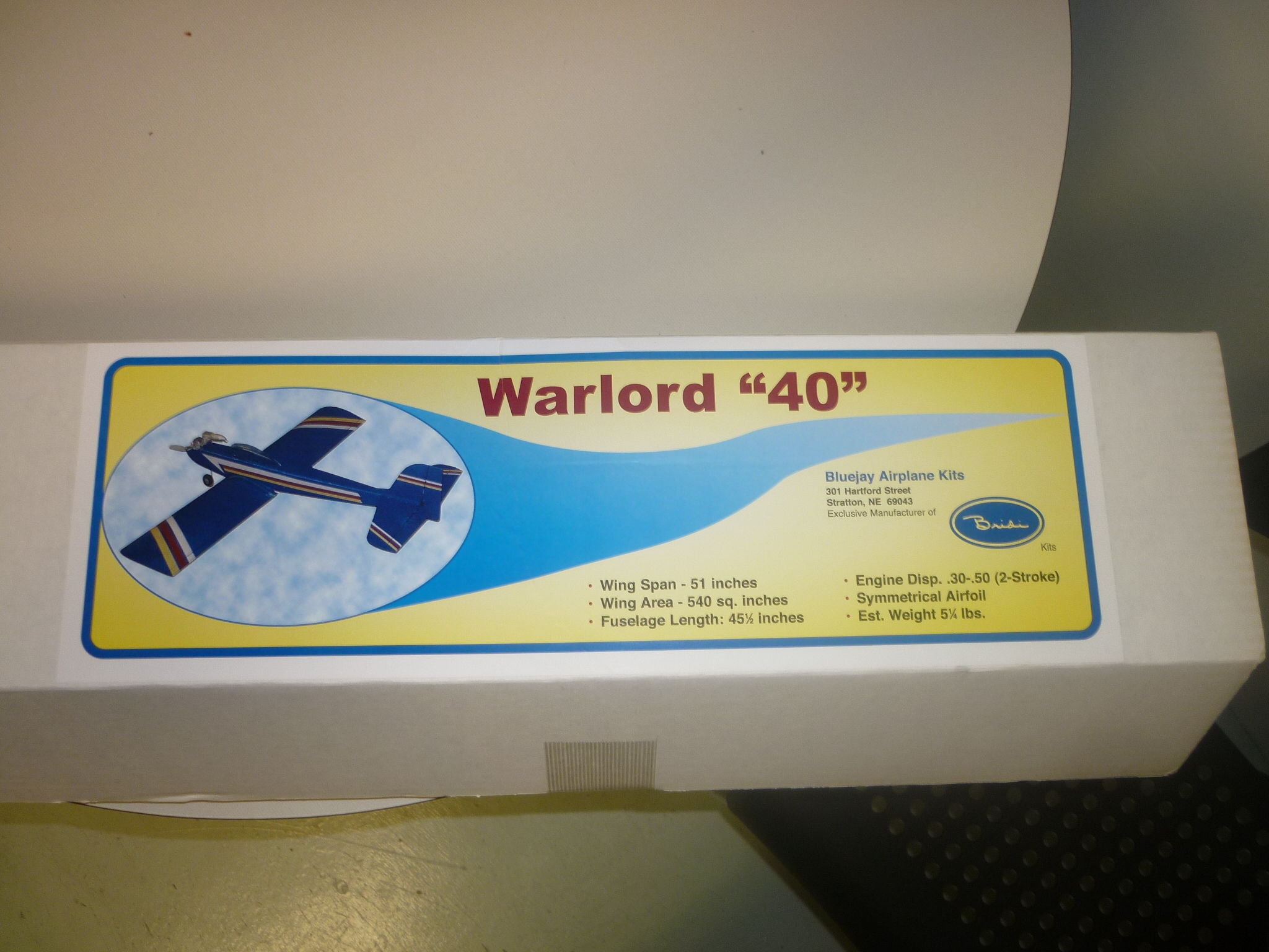
Just picked up a new Warlord 40 kit for Brent and I to build our the winter. It looks like a low wing version of the 4 Seasons 40. Old style build. Should be tough.
Jim
Jim
Last edited by Jim_Purcha; 10-03-2015 at 09:44 AM.
10-05-2015, 04:39 PM
#847
Join Date: Apr 2015
Posts: 40
Likes: 0
Received 0 Likes
on
0 Posts
A good friend of mine gave me his 30 year old super kaos 60 with a ys .60 and pipe.
After a little work freeing up the motor, brightening up the trim scheme converting to 2.4it flys
great! 1st plane with a tuned pipe wow! I have to be very judicious with the power!
It's a very smooth flying and aerobatic plane.much better flying than the chipmunk that met its end.
anyways here it is
10-06-2015, 02:32 AM
#848

You'll find nose high landings are really great! also its slow inverted flybys are great!! enjoy it its a great bird, ALL the "Kaos" line are great flyers..you'll see a slight tail wag on a high speed dive with a tail wind, its normal..
01-01-2016, 10:02 AM
#849

Earlier in the year I picked up a framed Kaos built from a Bridi Kit for a whopping 20.00. I immediately picked up a .61 FSR for it and then tucked them away for a couple months. After finishing a few other projects I pulled it out and began covering. I'm quite happy with the outcome. Truth be known it was an experiment on how well the color scheme was going to work as I plan to use the same scheme on a Reed Falcon. Unfortunately on initial run up it was discovered that the engine bearings are bad, will have to wait until the postman drops off the new set.
