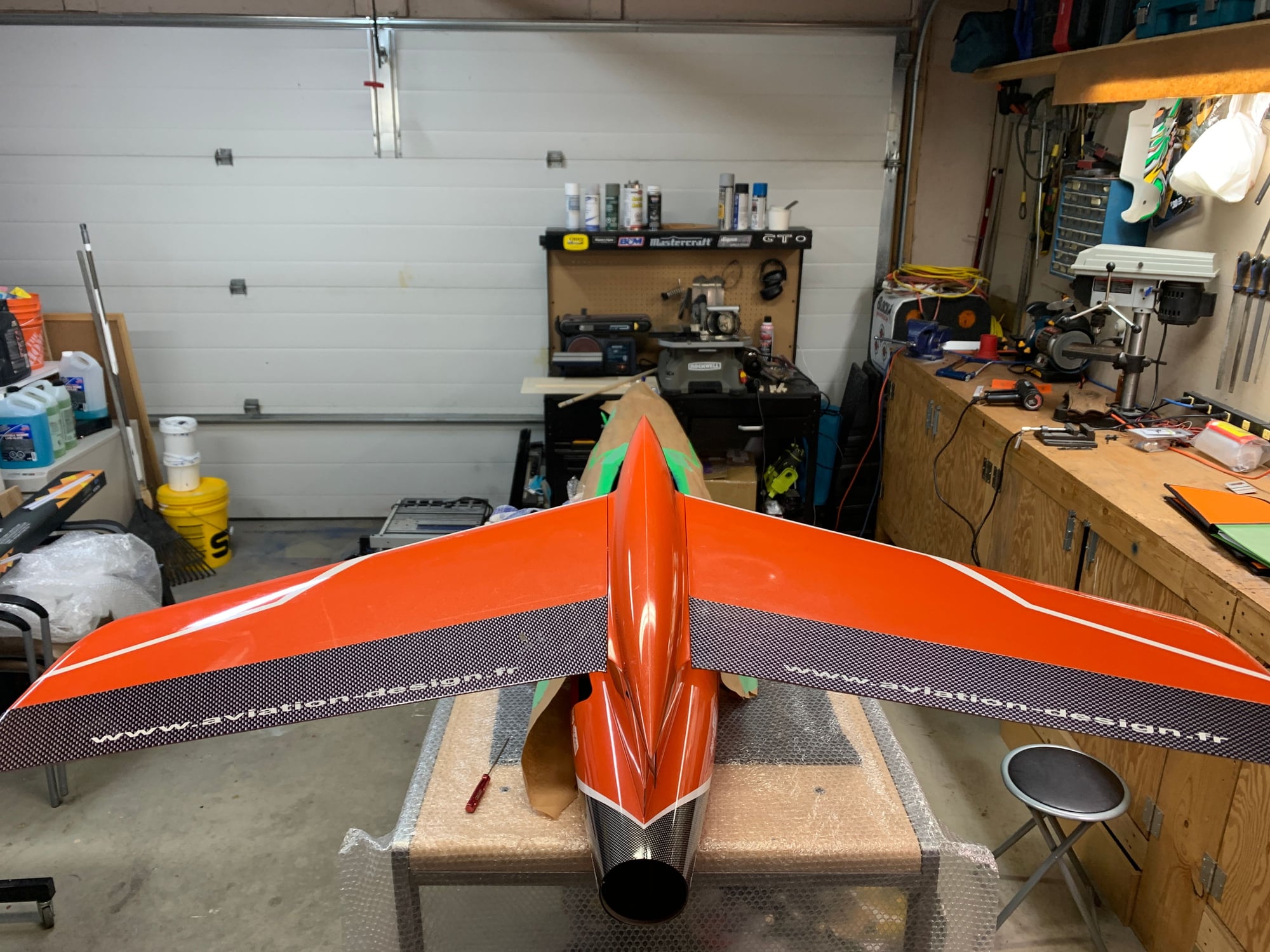
Aviation Design Diamond Assembly!


The following users liked this post:
Tom ling (11-23-2020)
 11-19-2020 | 07:52 AM
#28
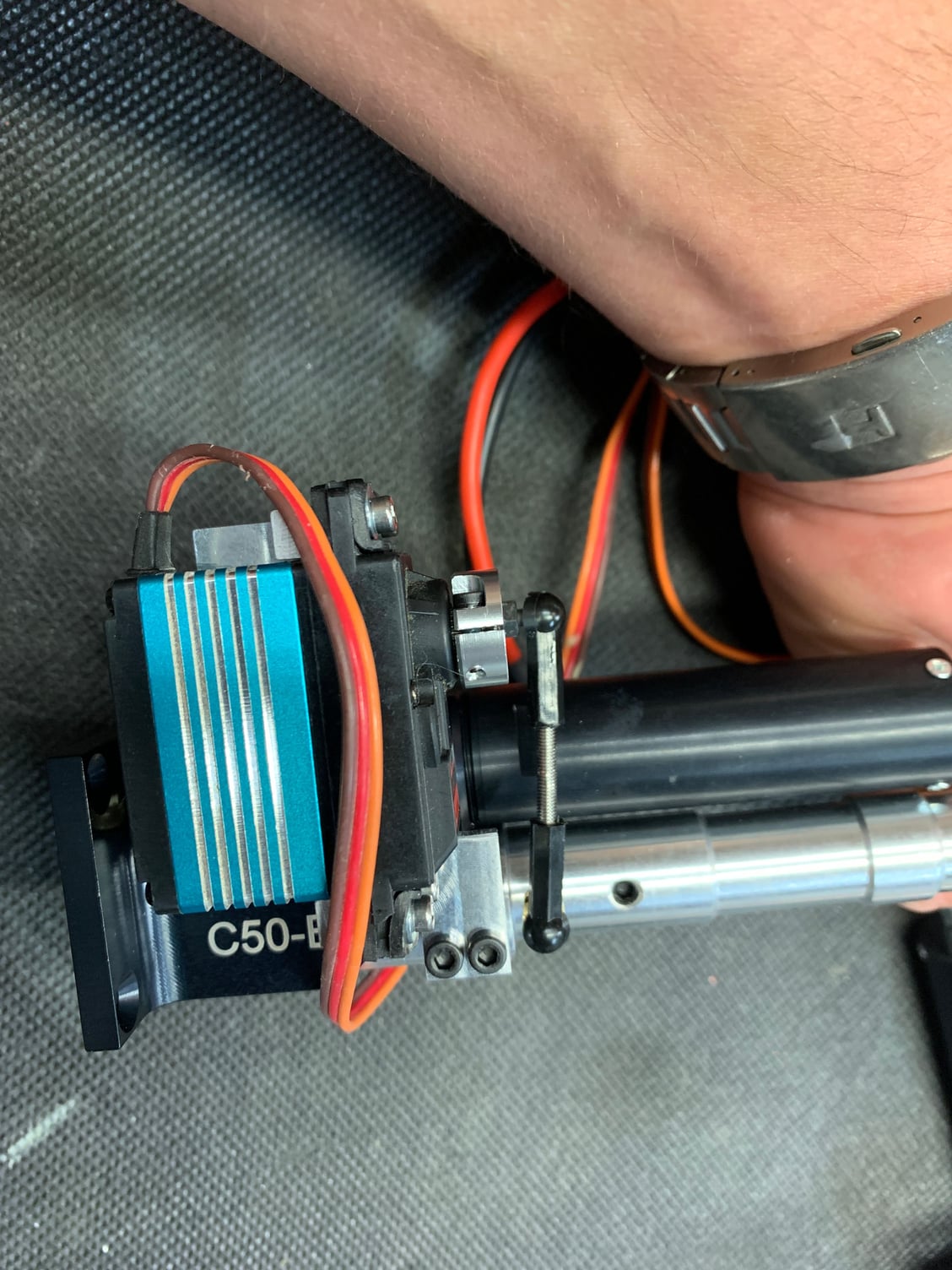
If you watch the video, I explain it but basically don't over tighten the set screw on the vertical risers for the servo mount. If you do it right you can get it at a 90 degree angle when it's fastened.
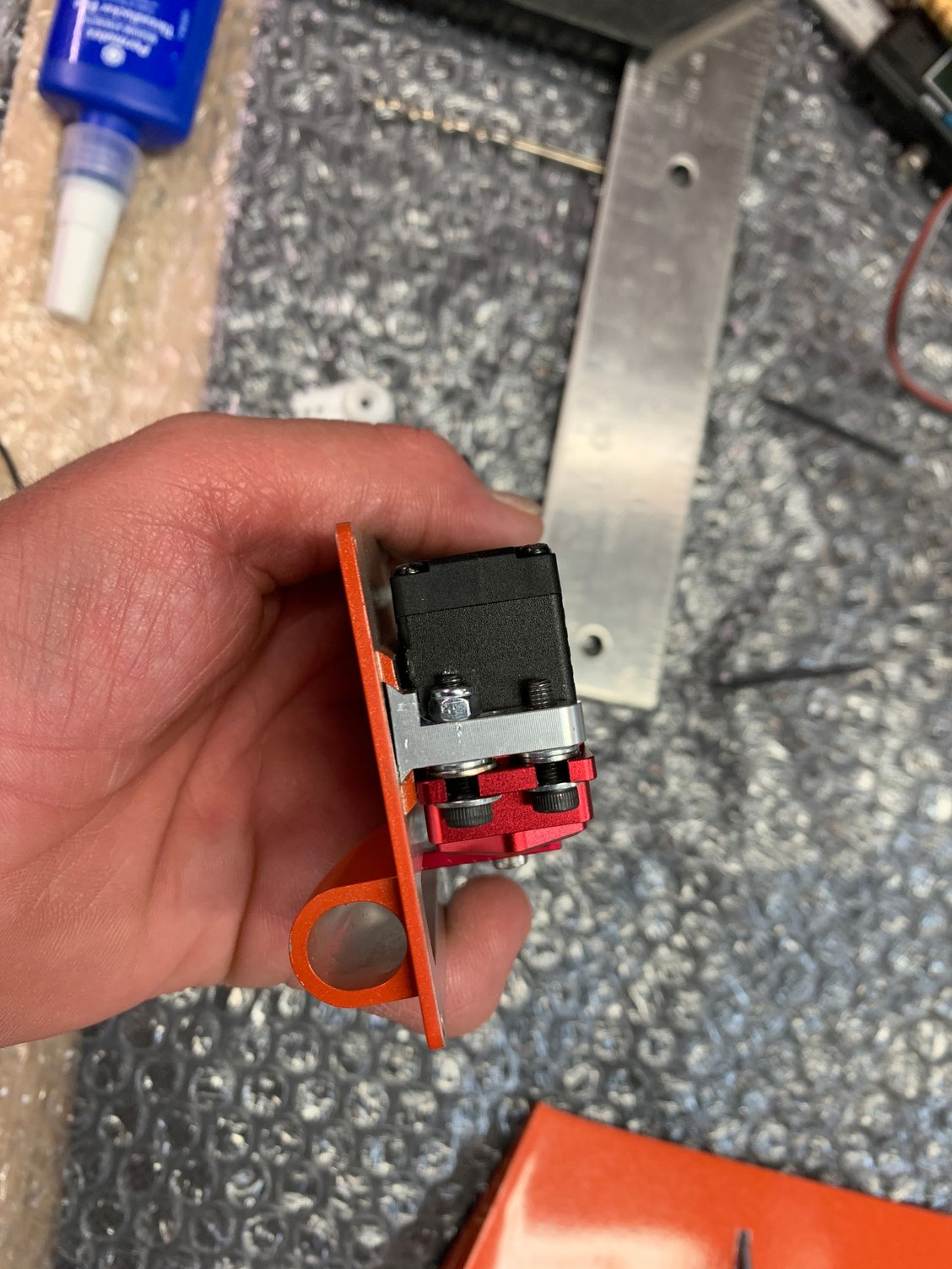
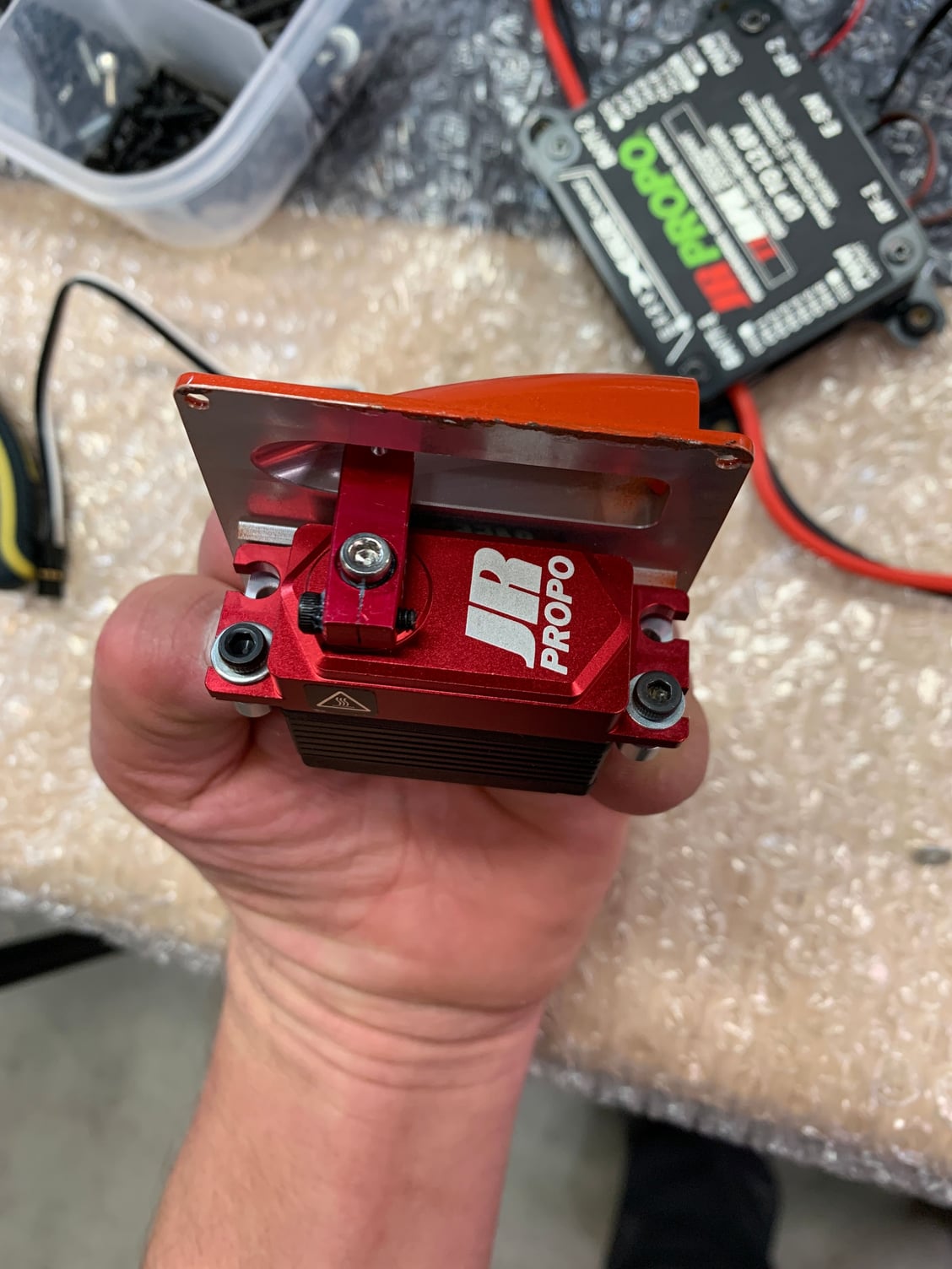
2 x 3mm washers needed behind servos to bring into proper alignment. This pictures shows the wrong adjustment on the servo mount. See the angle between the plate and the mount.
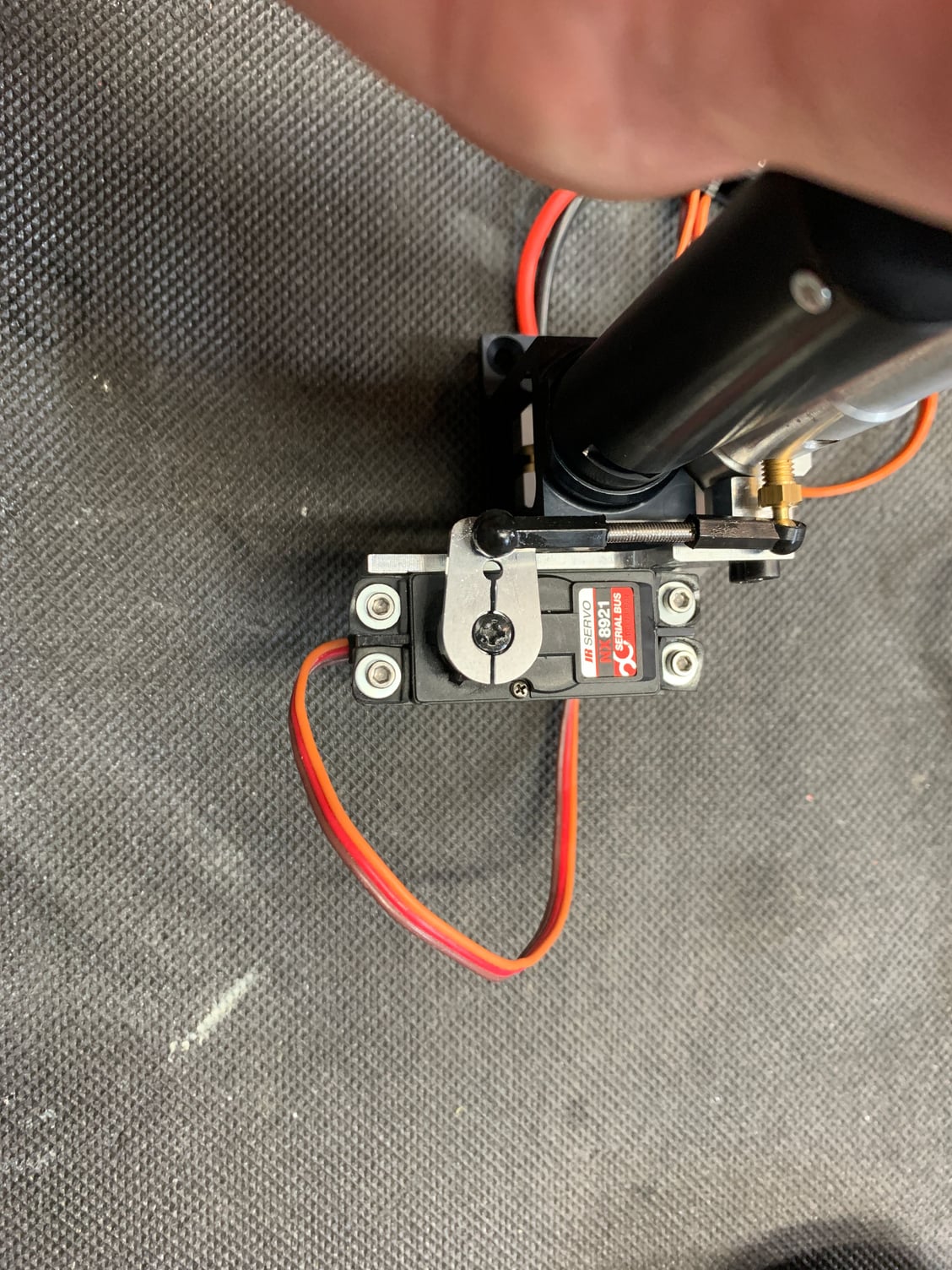
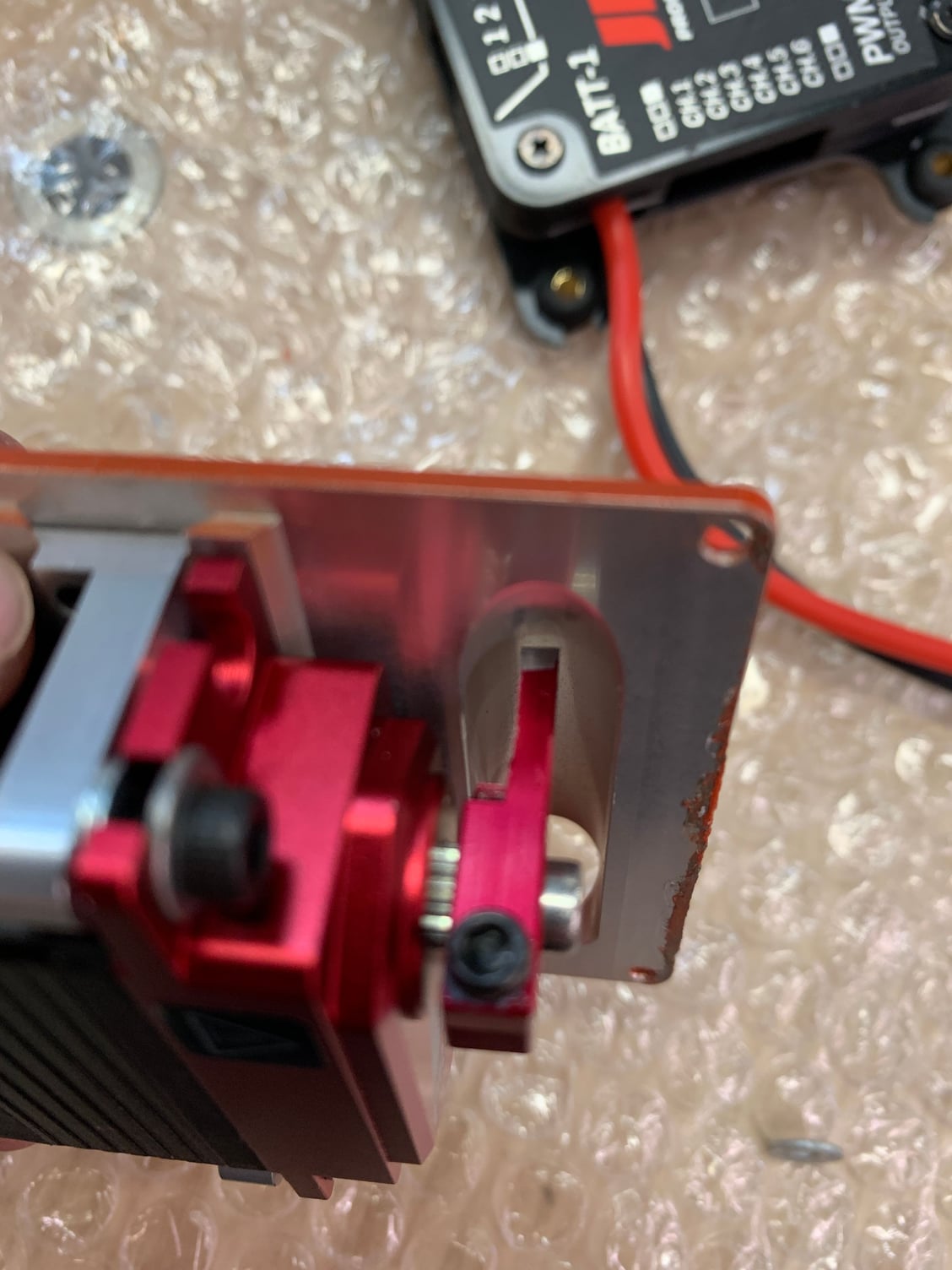
mount is nice and level.
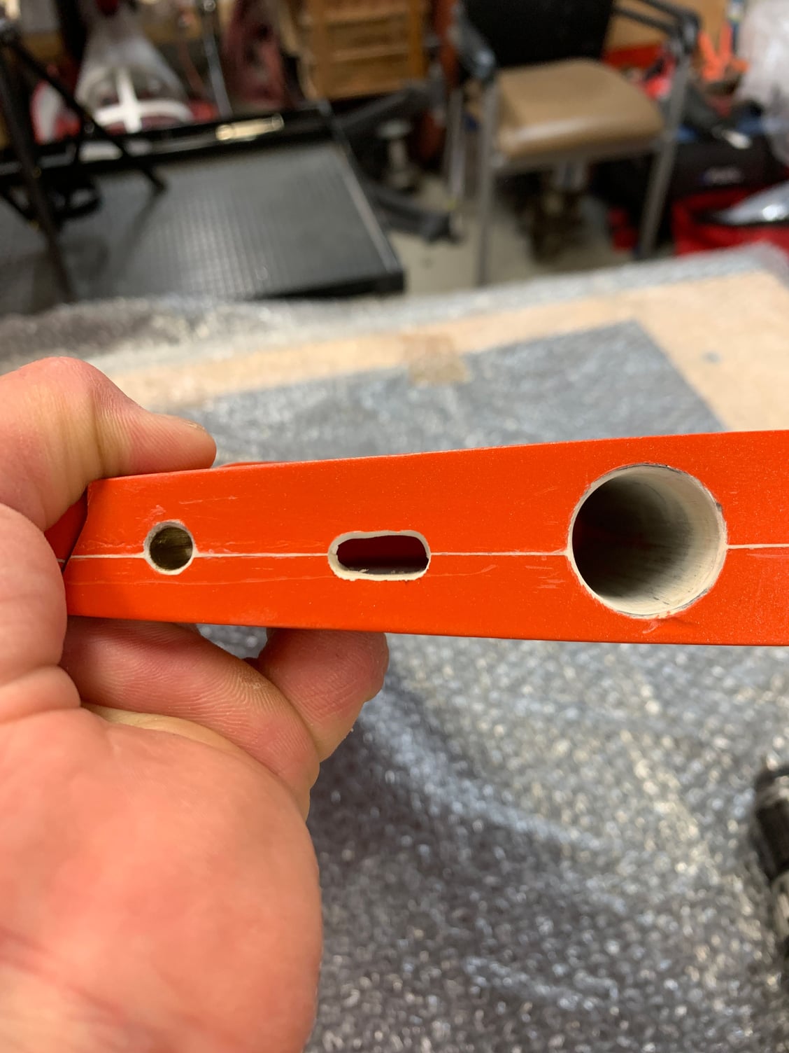
The top hole is sized correct to tap 3mm threads which makes lining everything up much easier. nut and bolt was used on bottom hole.
2 x 3mm washers needed behind servos to bring into proper alignment. This pictures shows the wrong adjustment on the servo mount. See the angle between the plate and the mount.
mount is nice and level.
The top hole is sized correct to tap 3mm threads which makes lining everything up much easier. nut and bolt was used on bottom hole.
11-19-2020 | 07:55 AM
#29
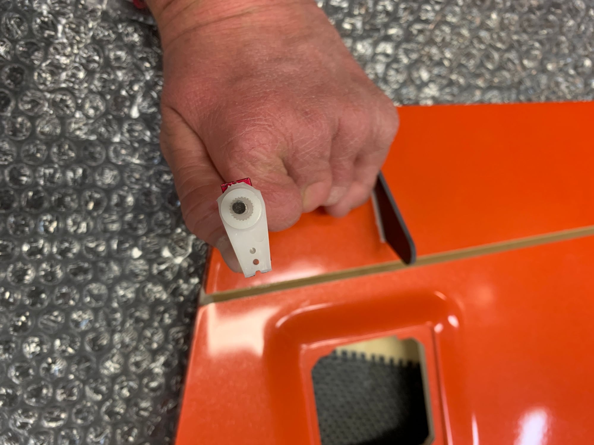
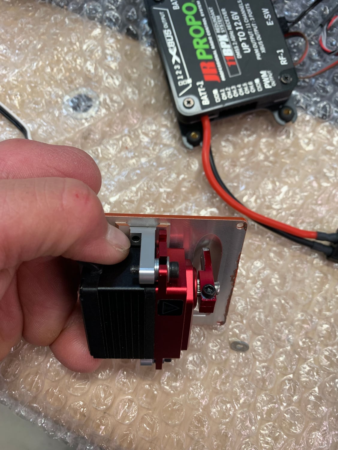
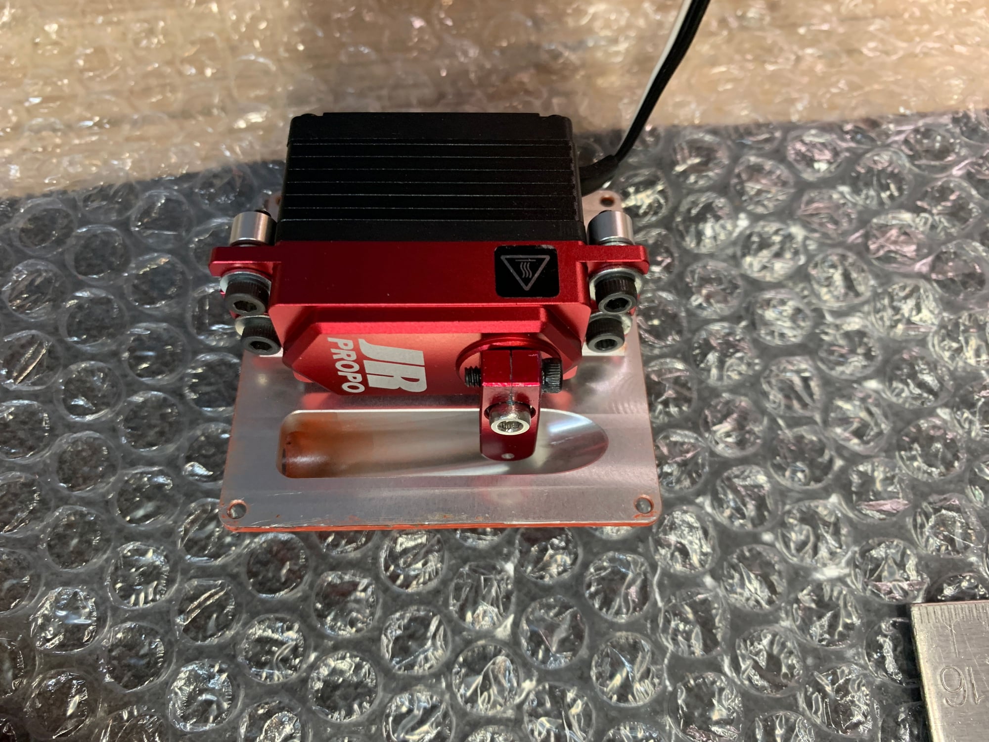
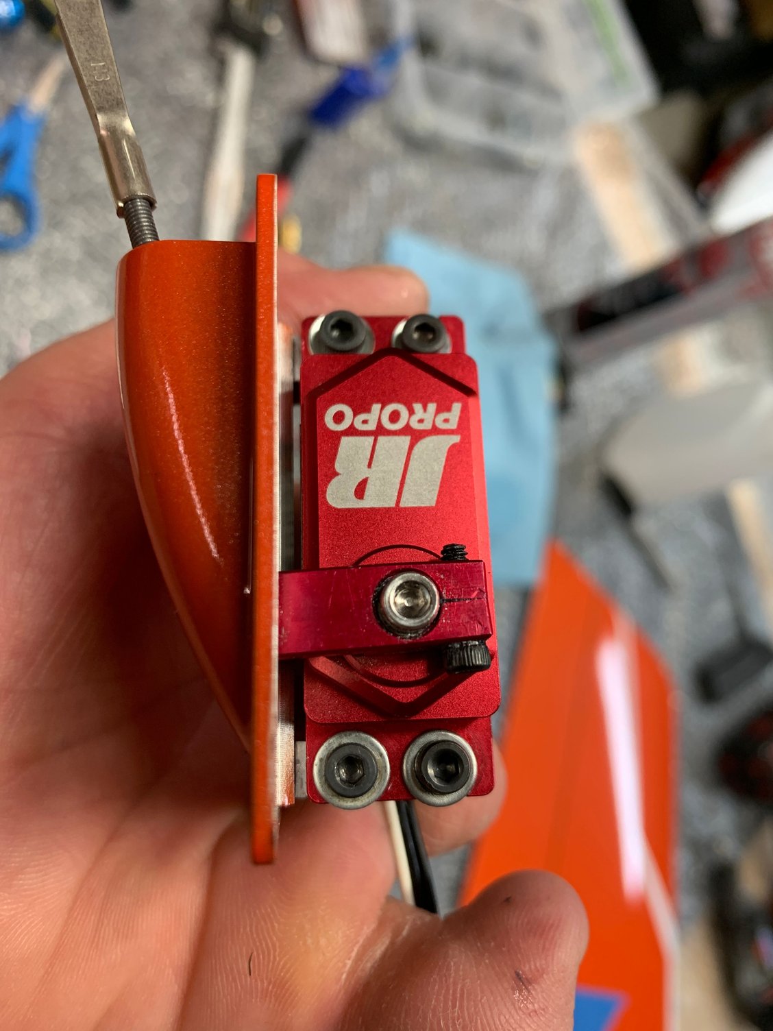
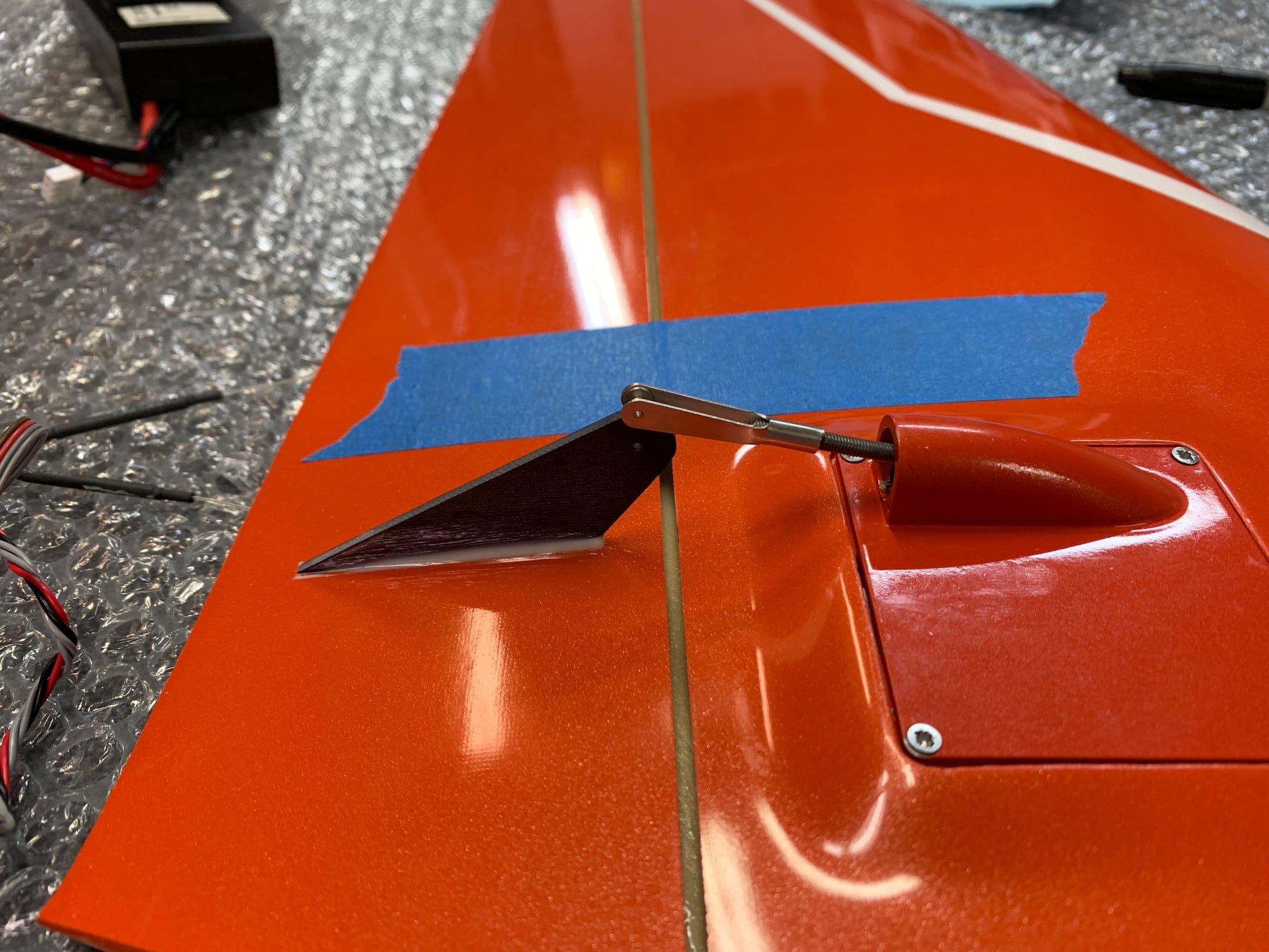
Servo does not need to be tight against the cover. If it is, you may run into clearance issues. there is room in the servo mount to adjust a few MM's away from the mount which makes everything work.

Servo tight against cover
servo spaced out from cover.
Servo tight against cover
servo spaced out from cover.
11-19-2020 | 07:59 AM
#30
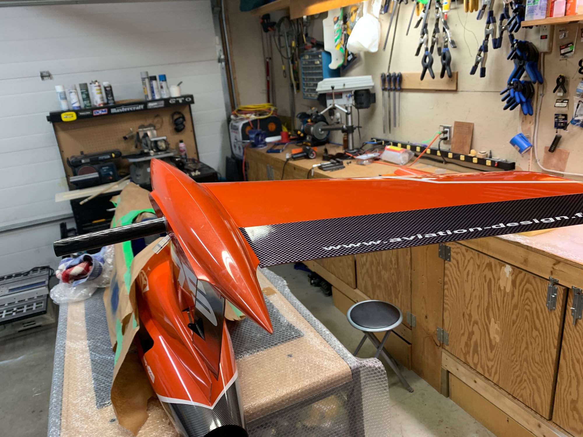
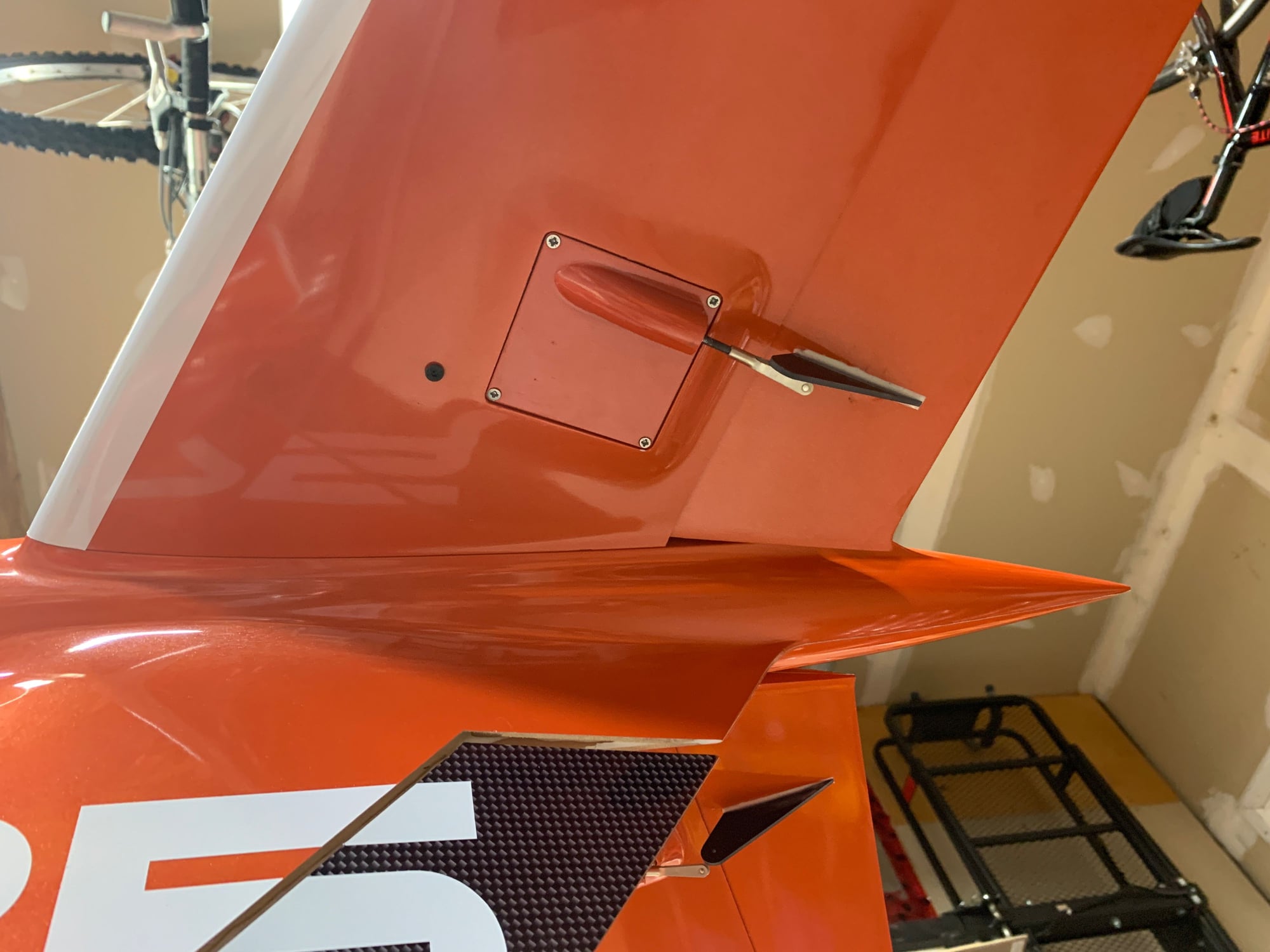
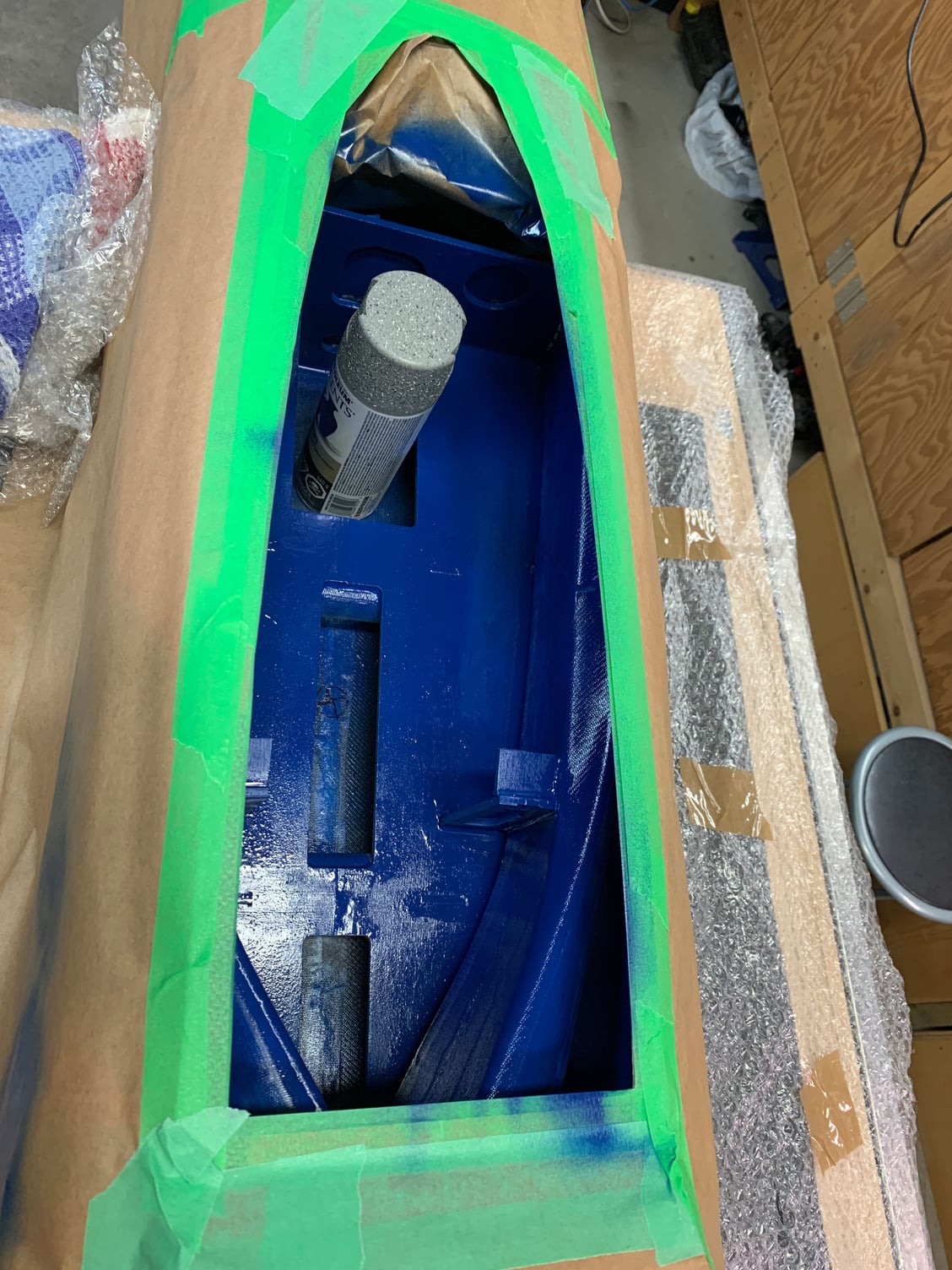
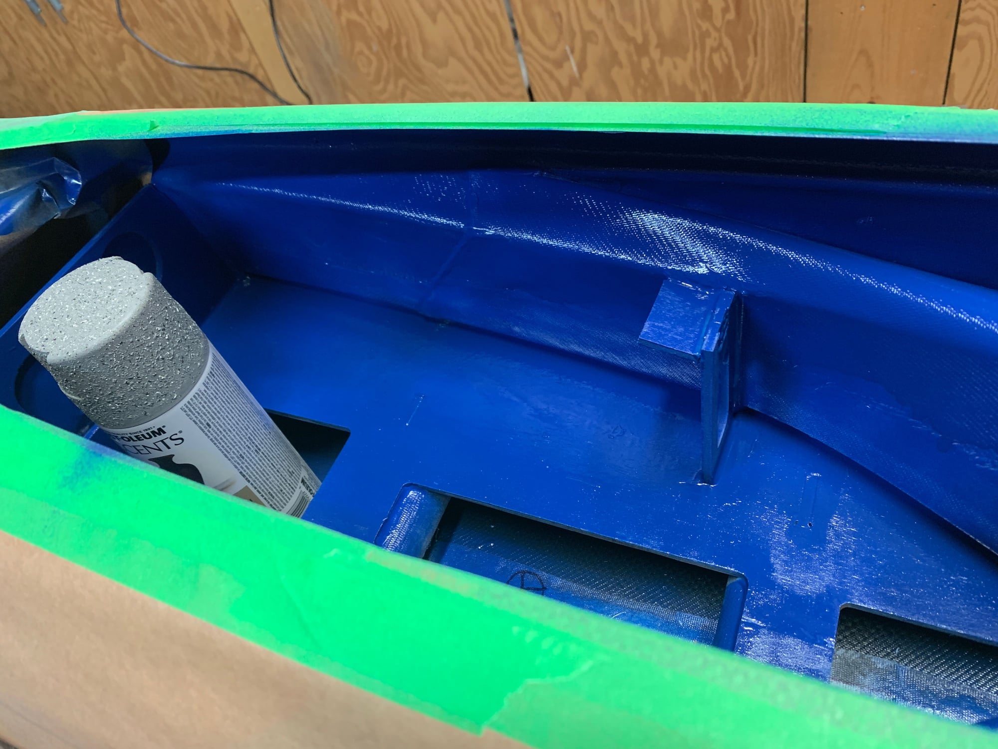
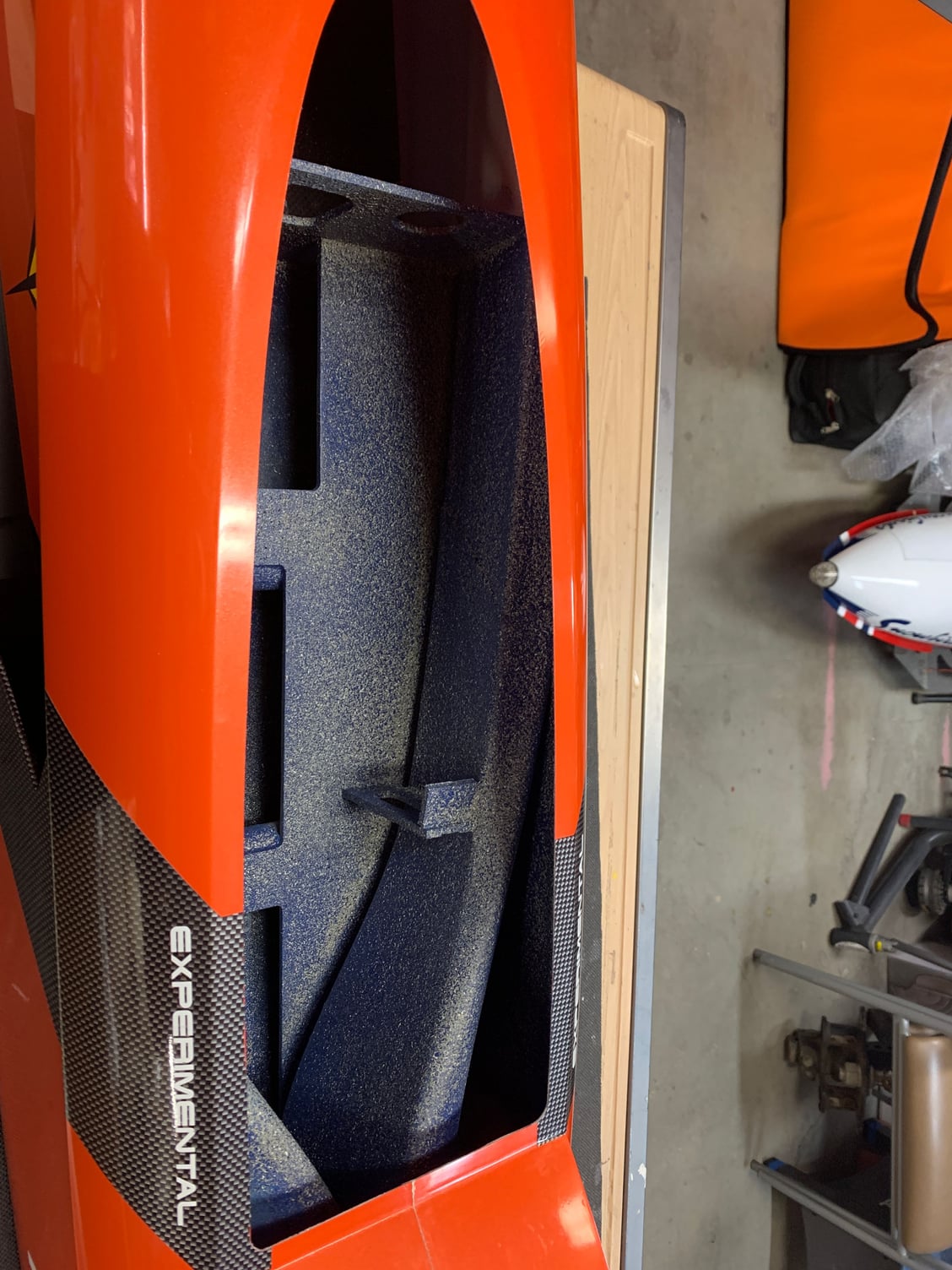
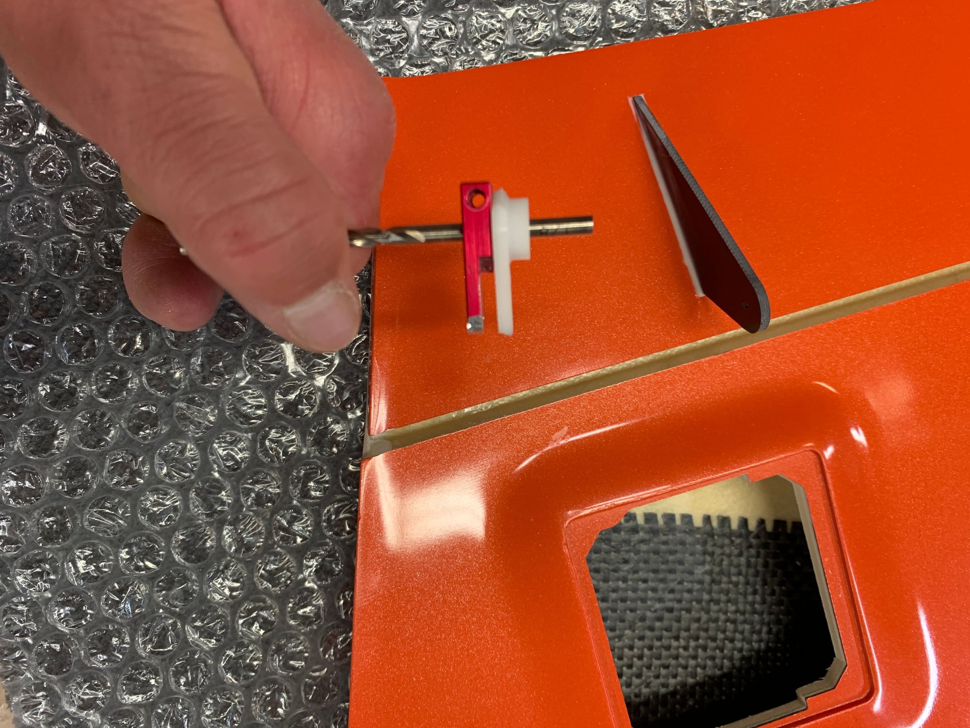
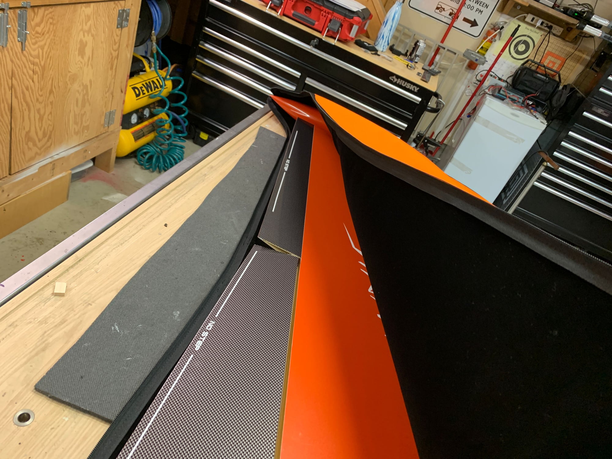
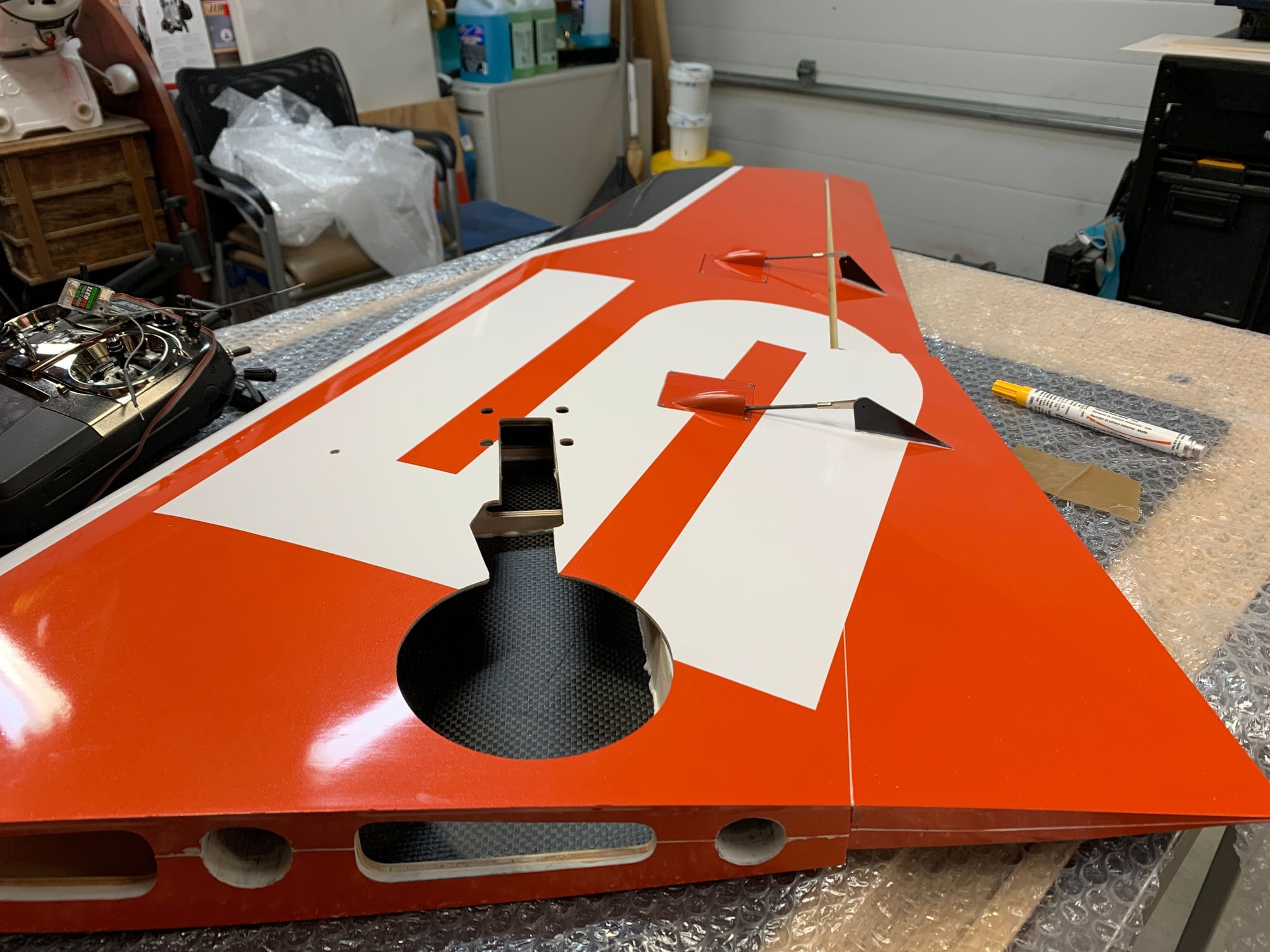
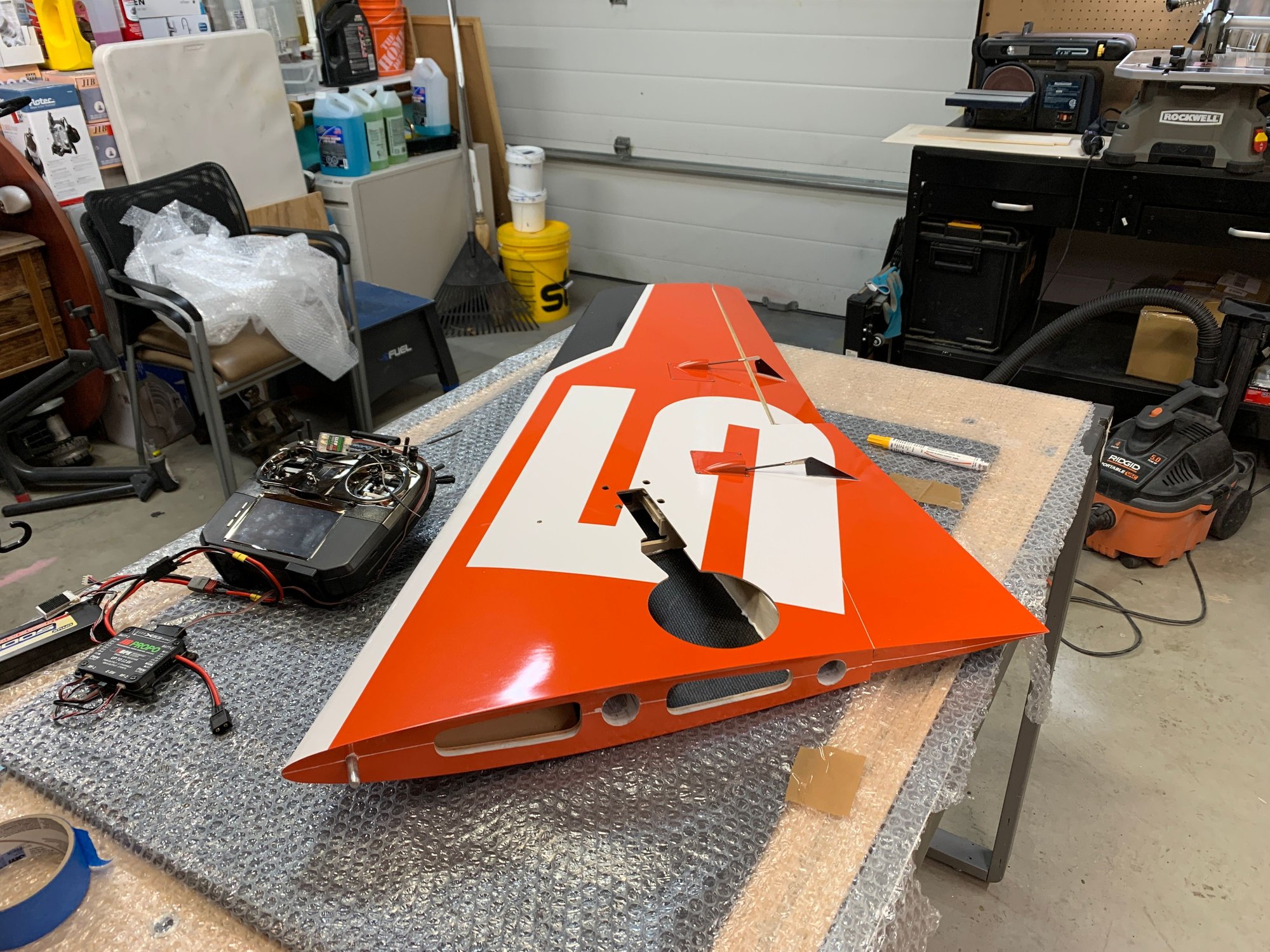
Last batch of pictures. servo mounting areas need to be opened up slightly to accept aluminum mounts and servos.
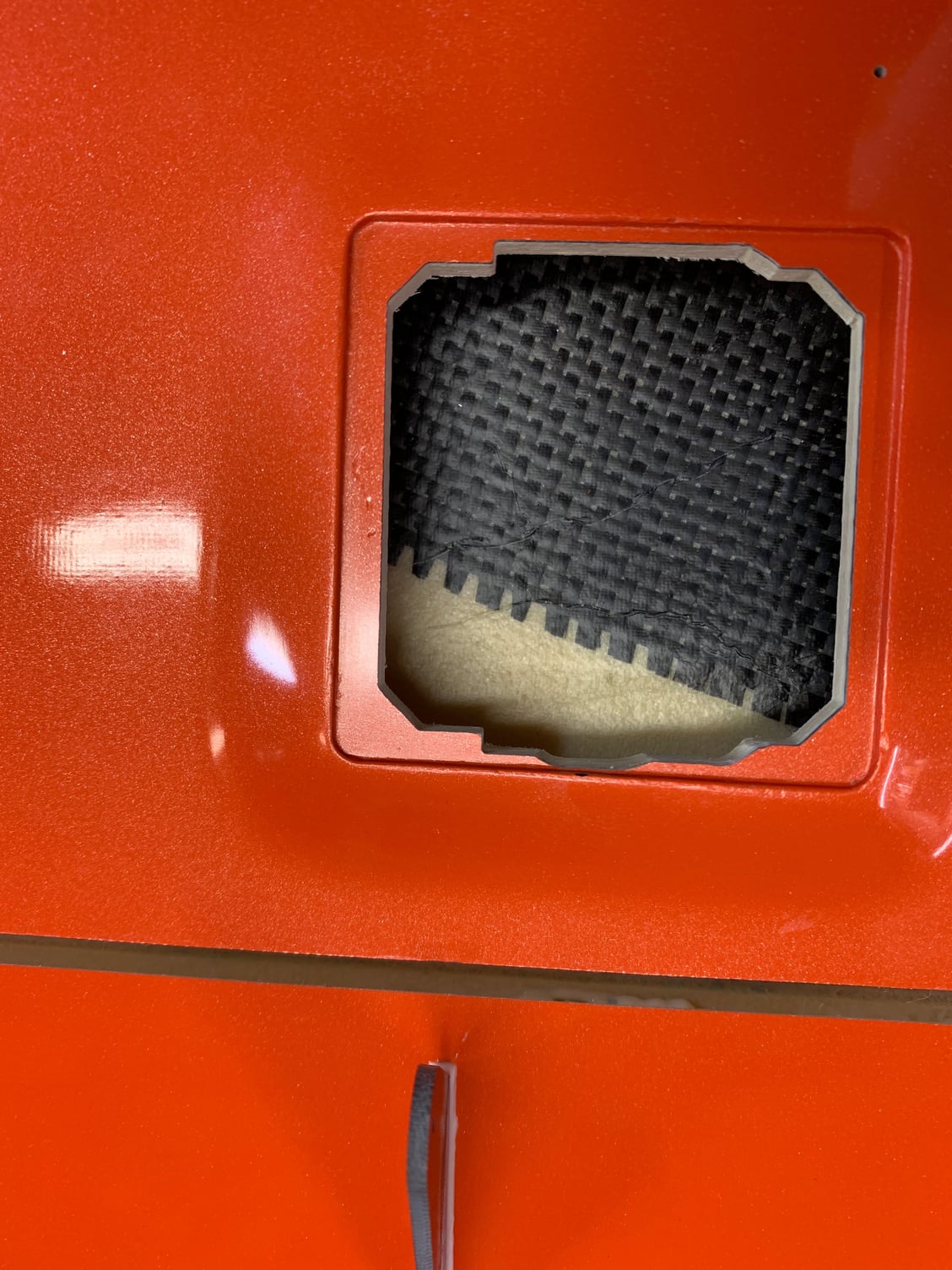
Opening in elevators. opened these up more later on.
Will do final clevis attachment/surface centering later.
Pitot Tube added for JR Speed Sensor!
Opening in elevators. opened these up more later on.
Will do final clevis attachment/surface centering later.
Pitot Tube added for JR Speed Sensor!

The following users liked this post:
Canadian Man (11-19-2020)


The following users liked this post:
Canadian Man (11-19-2020)
11-19-2020 | 01:26 PM
#34

I like how you can access the sbus settings for the servos and not have to have the servo directly connected to the radio. I don't think you showed it in this video, but I believe it was on one of the F18 videos. On my 18MZ I need to connect the servo to the back of the radio. Being able to make setting changes while the servos are installed is a game changer.
11-19-2020 | 07:25 PM
#36
I like how you can access the sbus settings for the servos and not have to have the servo directly connected to the radio. I don't think you showed it in this video, but I believe it was on one of the F18 videos. On my 18MZ I need to connect the servo to the back of the radio. Being able to make setting changes while the servos are installed is a game changer.
11-19-2020 | 07:30 PM
#37
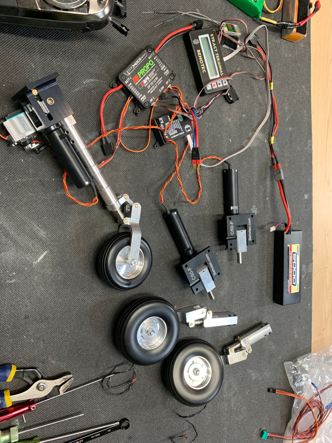
Yea Deeforce is the place. basically the radio comes with 16 stock channels and you can expand to get 28. So if you remove channel 16 you switch it to 4 more channels and now you have 19 Channels. Remove channel 15 and now you have 22 channels. The 11bpx that i'm using in this Diamond has 3 xbus outputs which can be 3 x bus channels or 6 xbus channels or 12 x but channels. The 16 bpx I used in the F18 Build is completely open xbus/pwm. A couple years ago I didn't understand it all but once I wrapped my head around how the Bus Systems work i love the simplicity of it.
Just look at our turbines now. They too are using a bus system so one cable from the data box (ECU or DRM) to the turbine and done.
Love this advancement in technology!
Just look at our turbines now. They too are using a bus system so one cable from the data box (ECU or DRM) to the turbine and done.
Love this advancement in technology!
11-22-2020 | 06:40 PM
#40
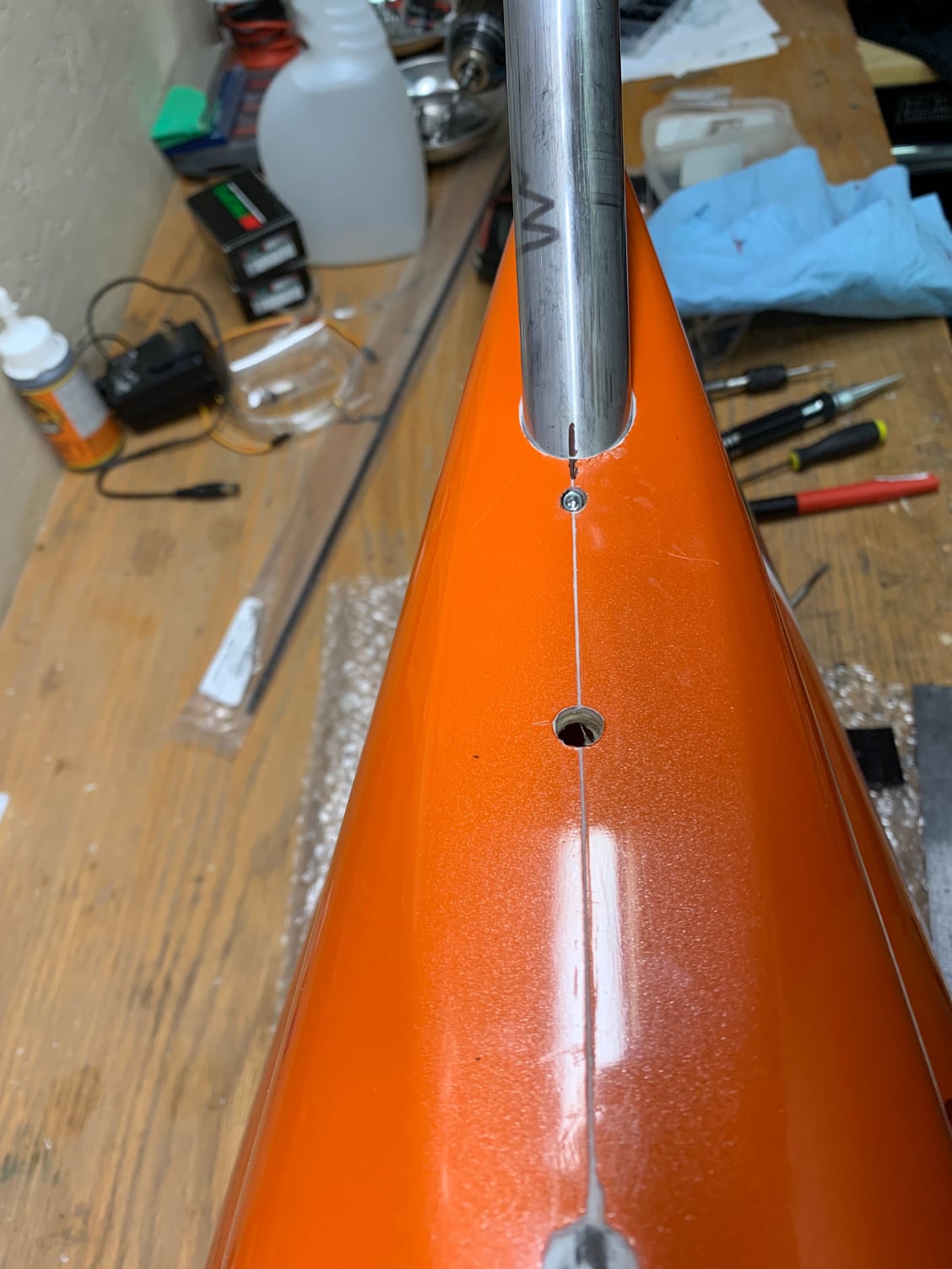
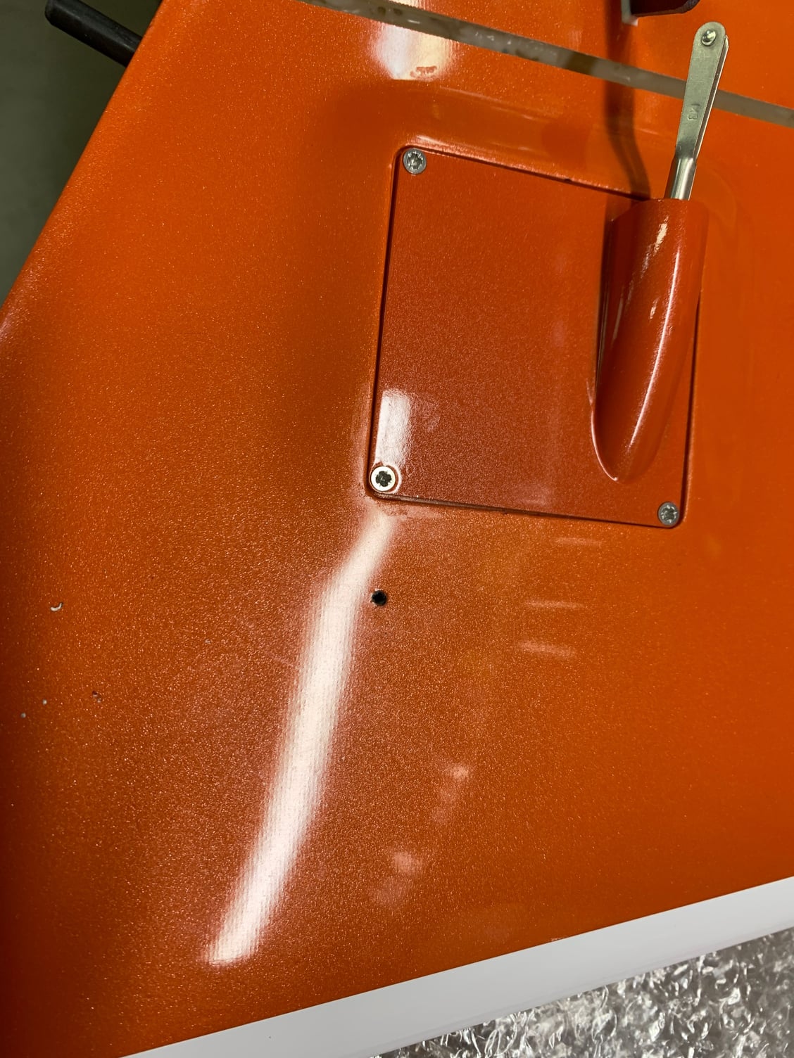
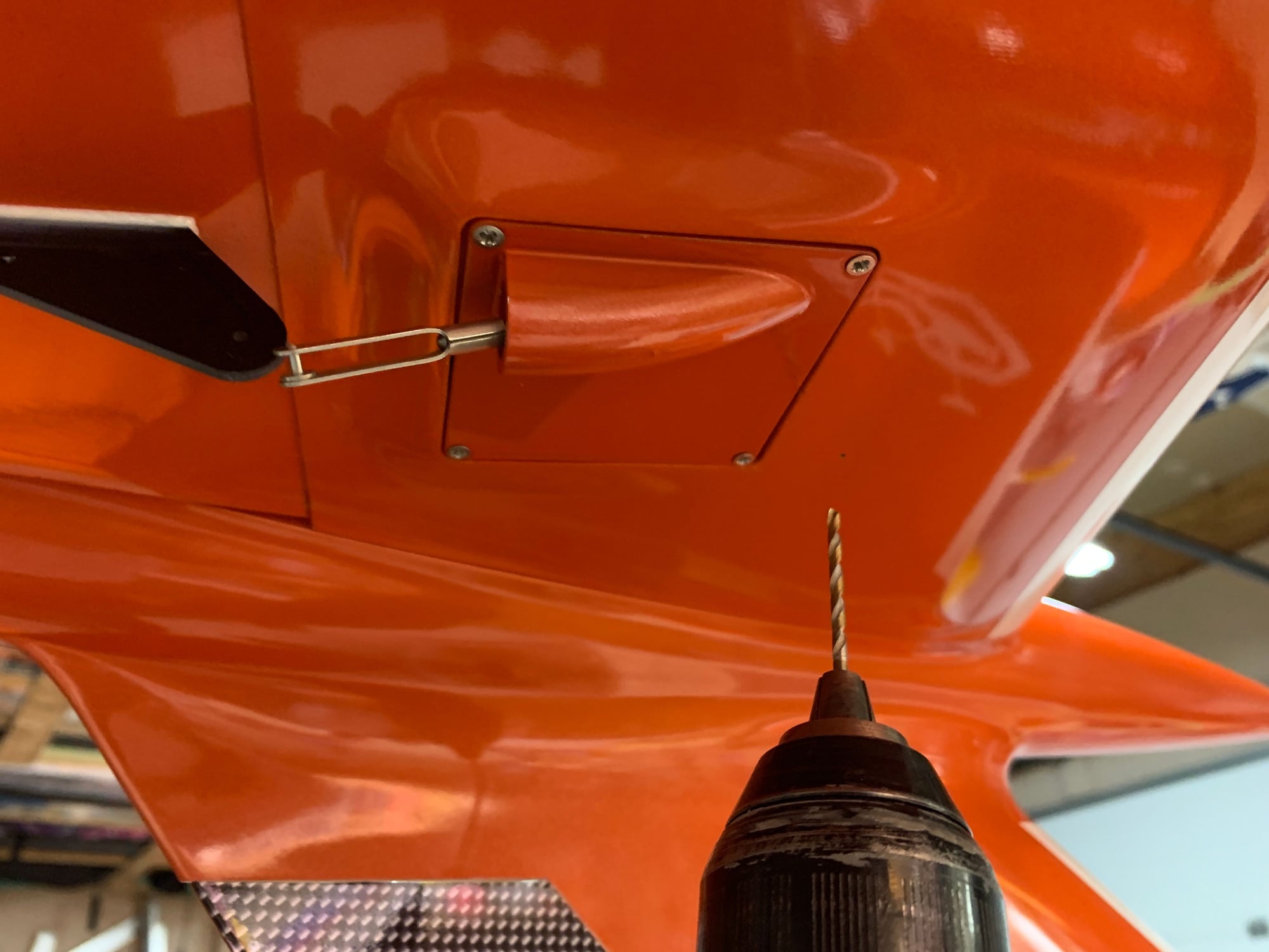
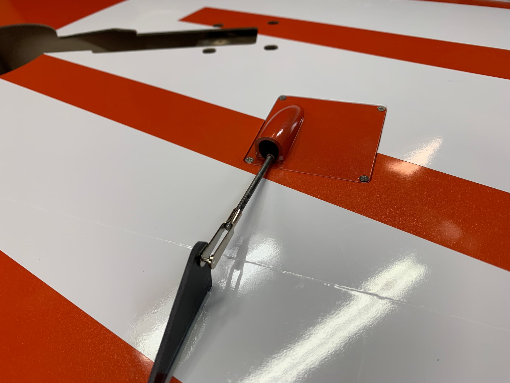
Rudder tube installed, marked and drilled, threaded with a 4-40 threads and bolt installed.
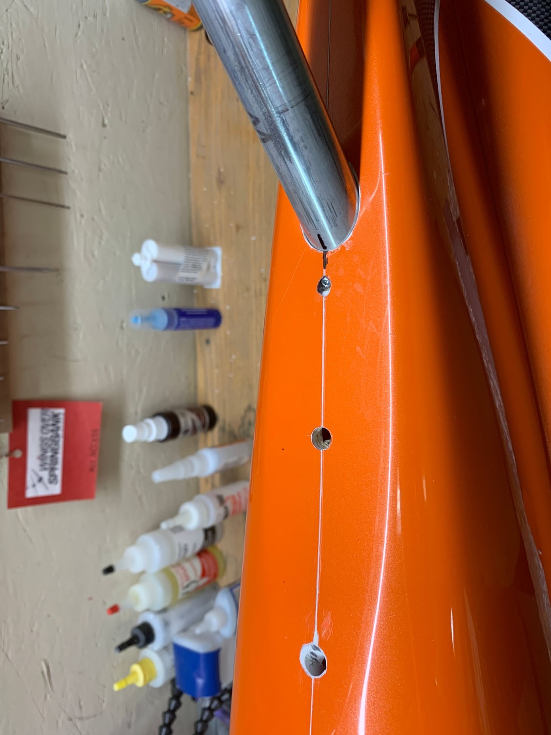
view of the top of the rudder tube. Blind nut used for this point with a hardwood dowel installed with gorilla glue.
Shot of the rudder bolt hole
Final Rudder connection. Bolt recessed into skin as there is plywood under to tighten too.
11-24-2020 | 02:49 AM
#41

Hi Jonathan
In the latest issue of RC Jets International there is an article on the Diamond and Sky Candy lights and what they did to mould the lenses on the tip tanks and on top of the rudder.
Kind Regards
James
In the latest issue of RC Jets International there is an article on the Diamond and Sky Candy lights and what they did to mould the lenses on the tip tanks and on top of the rudder.
Kind Regards
James
The following users liked this post:
Canadian Man (11-24-2020)
11-26-2020 | 07:45 AM
#44
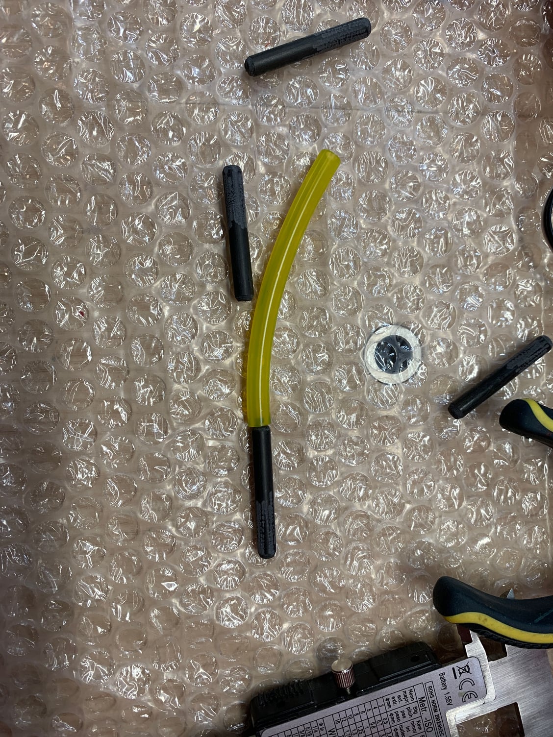
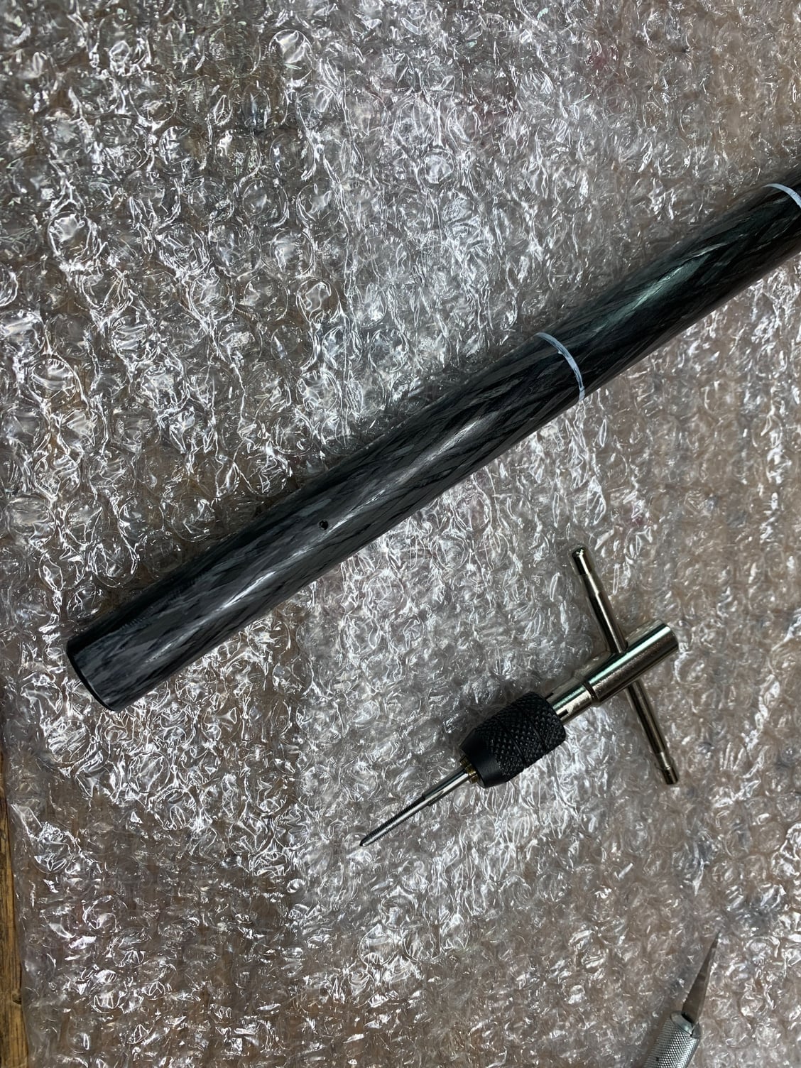
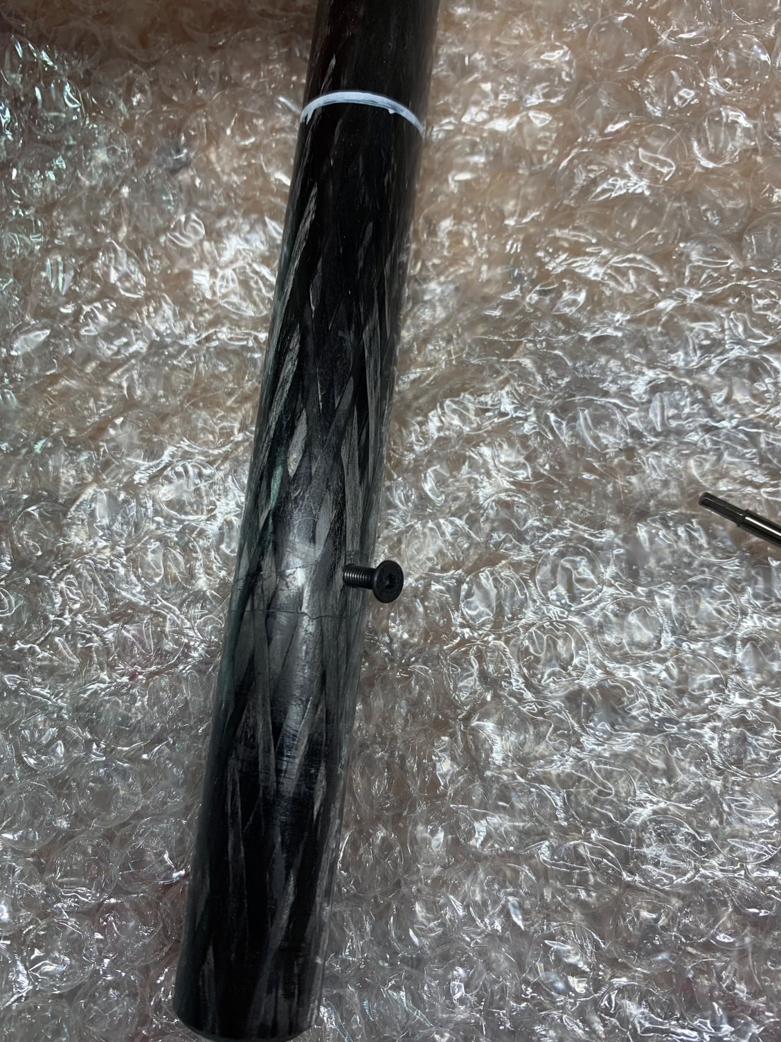
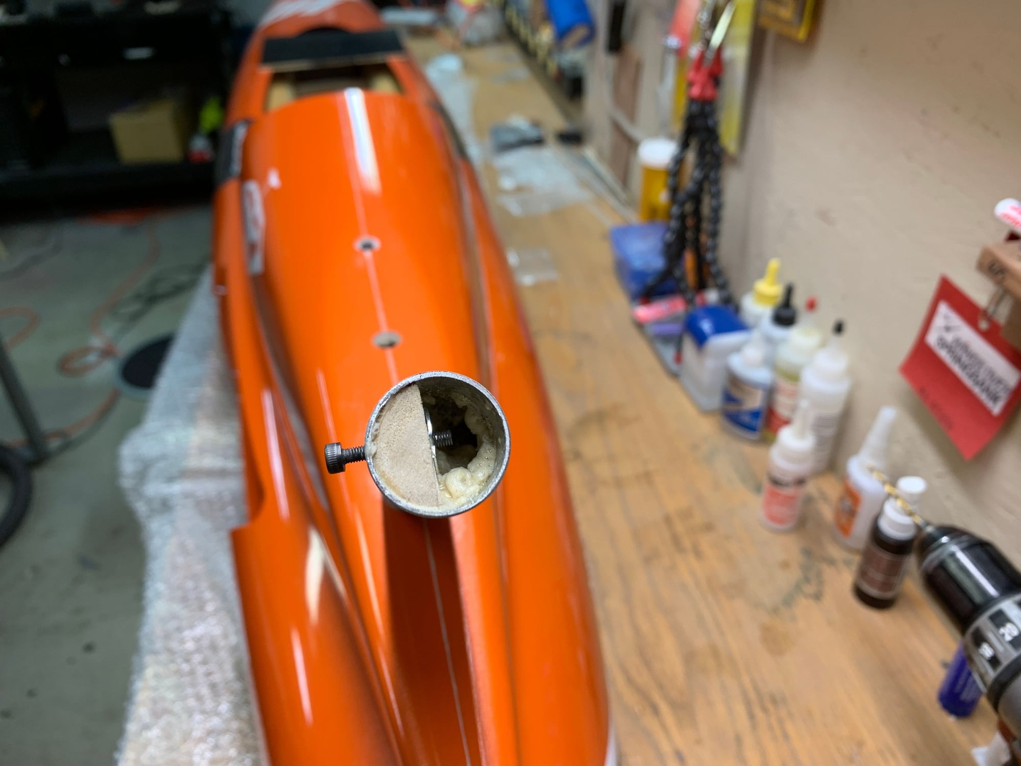
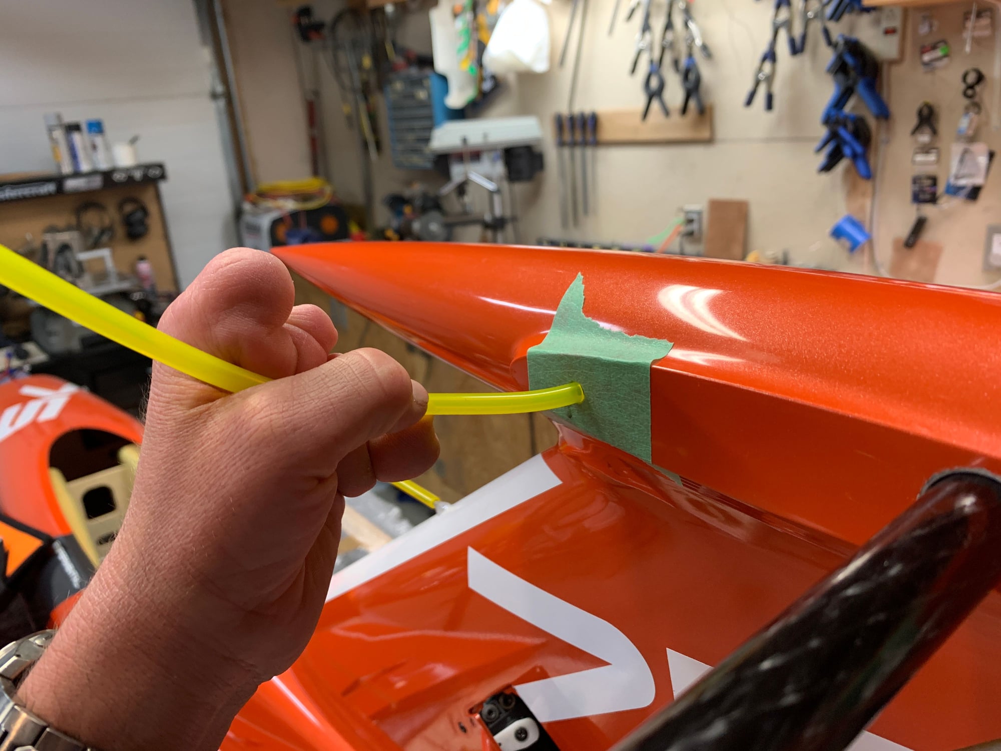
Need a spacer to install in the rudder so the carbon pins stay put and don't push in. The hole goes all the way through. I didn't have a dowel that would work so I used tygon.
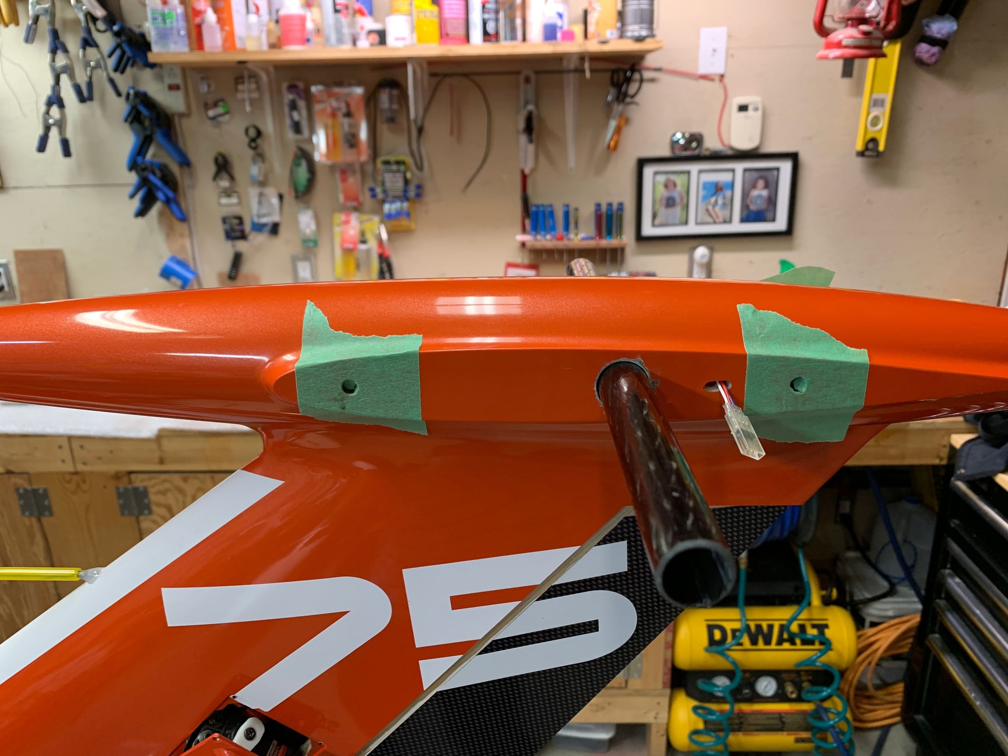
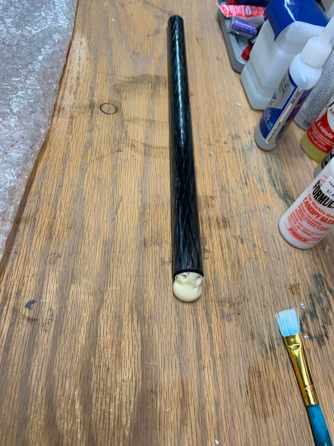
Elevator tube filled with a carbon dowel. Used gorilla glue to glue in. Gorilla glue is moisture cure so get dowel wet. coat carbon rod inside with glue. insert dowel and it expands as it cures.
The manual is very poor in this section when it comes to mounting the elevators. It basically says glue carbon rod in the rudder with CA. Glue pins into the elevators and assemble. DON'T Do That! if you do that things will probably not line up.
Seems like the best way is
1. install carbon rod into rudder.
2. install spacer in the dowel hole in the rudder to allow 1/2 of the pin to be in the rudder and 1/2 of the pin to be in the elevator.
3. check fit of everything
4. Sand down joint bumps on elevators if necessary.
5. install pins in rudder.
6. install glue in elevator pin holes.
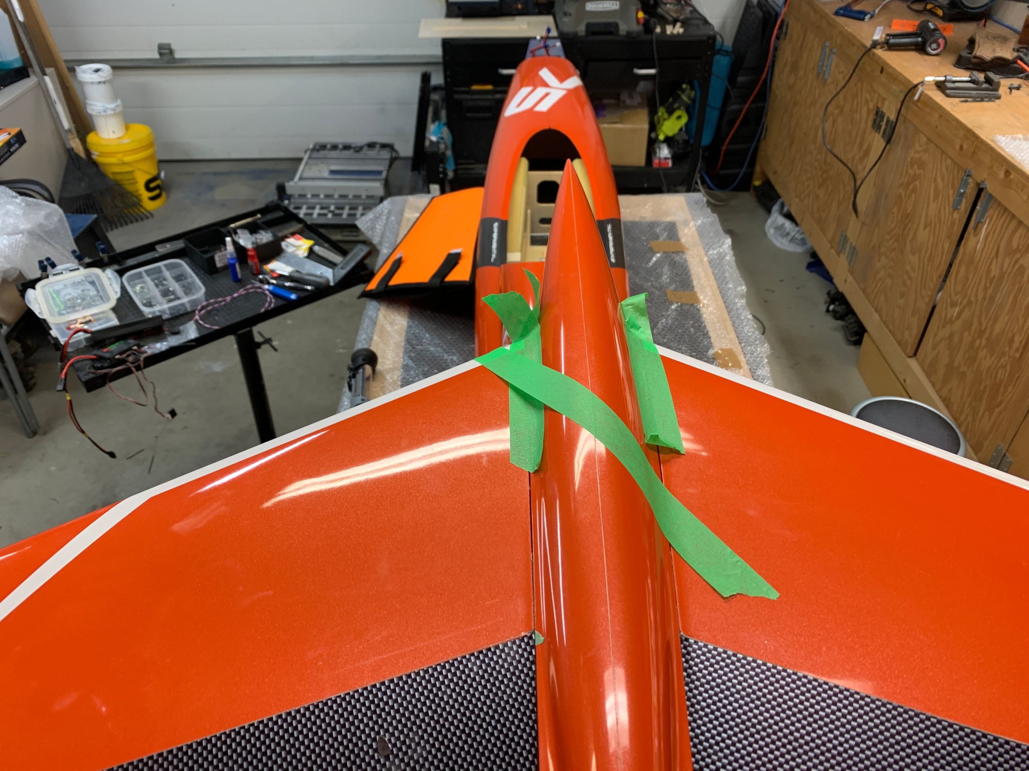
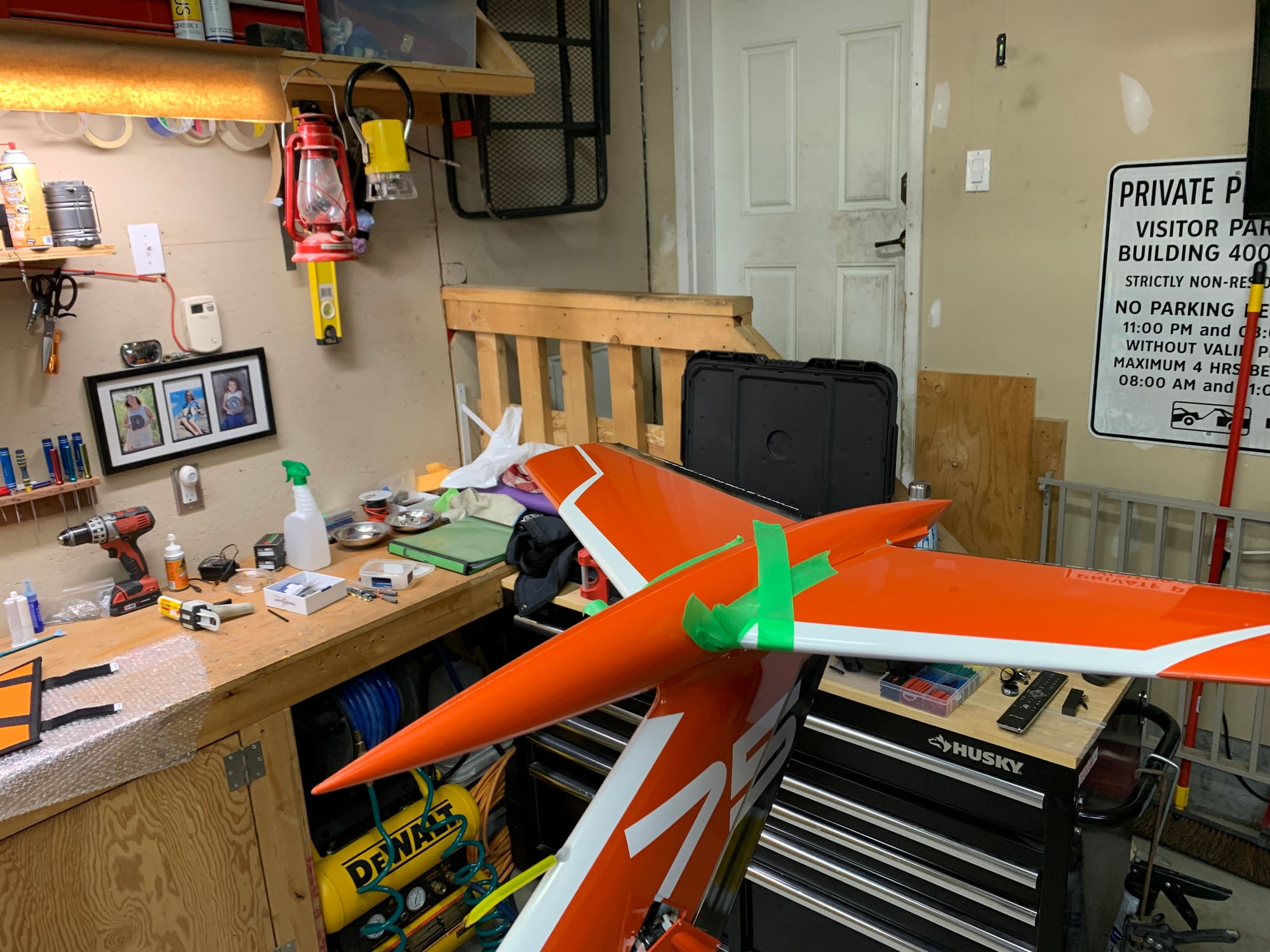
7. install elevators and tape in the center till cured.
My pin holes had lots of play so if you were to follow the manual it wouldn't work out so well.